Portland Castle, Dorset - English Heritage
Portland Castle, Dorset - English Heritage
Portland Castle, Dorset - English Heritage

Create successful ePaper yourself
Turn your PDF publications into a flip-book with our unique Google optimized e-Paper software.
RESEARCH REPORT SERIES no. 40-2013<br />
PORTLAND CASTLE<br />
PORTLAND BILL, DORSET<br />
REPORT ON GEOPHYSICAL SURVEY,<br />
NOVEMBER 2012<br />
Neil Linford<br />
REMOTE<br />
SENSING
Research Department Report Series 40-2013<br />
PORTLAND CASTLE, DORSET<br />
REPORT ON GEOPHYSICAL SURVEY,<br />
NOVEMBER 2012<br />
Neil Linford<br />
NGR SY 684 743<br />
© <strong>English</strong> <strong>Heritage</strong><br />
ISSN 1749-8775<br />
The Research Department Report Series, incorporates reports from all the specialist teams within the<br />
<strong>English</strong> <strong>Heritage</strong> Research Department: Archaeological Science; Archaeological Archives; Historic Interiors<br />
Research and Conservation; Archaeological Projects; Aerial Survey and Investigation; Archaeological Survey<br />
and Investigation; Architectural Investigation; Imaging, Graphics and Survey; and the Survey of London. It<br />
replaces the former Centre for Archaeology Reports Series, the Archaeological Investigation Report Series,<br />
and the Architectural Investigation Report Series.<br />
Many of these are interim reports which make available the results of specialist investigations in advance of<br />
full publication. They are not usually subject to external refereeing, and their conclusions may sometimes<br />
have to be modified in the light of information not available at the time of the investigation. Where no final<br />
project report is available, readers are advised to consult the author before citing these reports in any<br />
publication. Opinions expressed in Research Department Reports are those of the author(s) and are not<br />
necessarily those of <strong>English</strong> <strong>Heritage</strong>.<br />
Requests for further hard copies, after the initial print run, can be made by emailing:<br />
Res.reports@english-heritage.org.uk.<br />
or by writing to <strong>English</strong> <strong>Heritage</strong>, Fort Cumberland, Fort Cumberland Road, Eastney, Portsmouth PO4 9LD<br />
Please note that a charge will be made to cover printing and postage.<br />
© ENGLISH HERITAGE 40-2013
SUMMARY<br />
A Ground Penetrating Radar (GPR) survey was conducted at <strong>Portland</strong> <strong>Castle</strong>, <strong>Portland</strong><br />
Bill, <strong>Dorset</strong>, to assist with the investigation of ongoing water ingress through the external<br />
walls into the Captain’s chamber. Access for the survey was provided by a two-tier<br />
scaffold platform over the vertical face of the external wall, to assess whether the GPR<br />
technique could reveal any useful information regarding the integrity of the structure. The<br />
results confirm sufficient penetration of the radar signal to detect reflections from the<br />
internal face of the wall and identified known features, such as the timber sockets<br />
protruding into the masonry visible from the interior. A potential area of degradation<br />
within the core structure of the wall is also indicated within the upper courses of masonry,<br />
which contrasts with the response over sound elements of the building.<br />
CONTRIBUTORS<br />
The field work was conducted by Neil Linford and Andy Payne with the assistance of<br />
Morgan Cowles.<br />
ACKNOWLEDGEMENTS<br />
The author wishes to express his thanks to the site custodians who were on hand to<br />
open the site to allow the survey to take place. Morgan Cowles kindly provided<br />
architectural plans that assisted with the interpretation of the data and compilation of the<br />
figures.<br />
ARCHIVE LOCATION<br />
Fort Cumberland.<br />
DATE OF FIELDWORK AND REPORT<br />
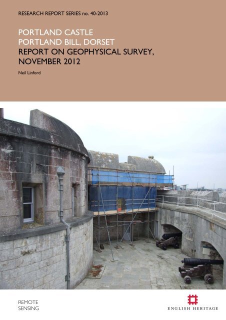
The fieldwork was conducted on the 11 th and 12 th November 2012 and the report was<br />
completed on 2 nd July 2013. The cover photograph shows a view over the gun deck<br />
towards the scaffold erected over the North Wall of the Captain’s Chamber for the GPR<br />
survey.<br />
CONTACT DETAILS<br />
Dr Neil Linford, Geophysics Team, <strong>English</strong> <strong>Heritage</strong>, Fort Cumberland, Fort Cumberland<br />
Road, Eastney, Portsmouth PO4 9LD.<br />
Tel: 02392 856761. Email: neil.linford@english-heritage.org.uk<br />
© ENGLISH HERITAGE 40-2013
CONTENTS<br />
Introduction .......................................................................................................................................................................... 1<br />
Method .................................................................................................................................................................................... 1<br />
Results ...................................................................................................................................................................................... 2<br />
Significant anomalies ........................................................................................................................................................ 2<br />
Discussion .............................................................................................................................................................................. 3<br />
Conclusion............................................................................................................................................................................. 4<br />
List of enclosed figures................................................................................................................................................... 4<br />
References ............................................................................................................................................................................. 6<br />
© ENGLISH HERITAGE 40-2013
INTRODUCTION<br />
<strong>Portland</strong> <strong>Castle</strong> (Scheduled Ancient Monument no. 22964) is one of a group of artillery<br />
forts, built on the orders of Henry VIII in 1540, specifically as one of a pair of forts<br />
guarding the anchorage of the <strong>Portland</strong> Roads. It takes an unusual fan-shaped plan-form,<br />
with a two-storey central tower or keep, flanking wings, and a curving wall facing the sea.<br />
The castle is externally built in fine <strong>Portland</strong> ashlar and retains many original features,<br />
though some post-Tudor features were removed when the castle came into guardianship<br />
in 1955. The castle is a Grade I listed building, the Captain’s house and entrance gateway<br />
are listed at Grade II* and other parts of the curtain wall are designated at Grade II.<br />
Ongoing incidents of water ingress in the West range of the <strong>Castle</strong> in the Captain’s<br />
chamber that have recently occurred are a concern and appear to be related to re-used<br />
beam sockets that have reduced parts of the north wall thickness to approximately<br />
300mm (Cowles 2011). Following a period of monitoring it appears that the problem is<br />
due to driven rain laterally through voids in the masonry exacerbated by the reduced<br />
cover over the beam socket detailing.<br />
The aim of the Ground Penetrating Radar (GPR) survey was to investigate whether this<br />
methodology could provide a means of non-invasive analysis at the site, to indicate the<br />
structural integrity of north wall and determine whether the presence and extent of any<br />
voiding could be established.<br />
METHOD<br />
The survey was conducted against the external face of north wall of the Captain’s<br />
Chamber from a two-tier, cantilevered scaffold to allow a safe working platform. Individual<br />
GPR traces were collected following <strong>English</strong> <strong>Heritage</strong> (2008) at 0.02m intervals along<br />
parallel profiles separated by 0.075m for the upper courses of masonry and at a 0.15m<br />
separation for the lower course (Figure 1). A Sensors and Software Pulse Ekko PE1000<br />
console with a 900MHz centre frequency antenna recording reflections through a 40ns<br />
window was used to collect the data with the antenna unit kept in close contact with the<br />
outer ashlar face of the wall.<br />
Post acquisition processing involved the adjustment of time-zero to coincide with the true<br />
ground surface, background and noise removal, and the application of a suitable gain<br />
function to enhance late arrivals. Representative profiles from the GPR survey are shown<br />
on Figures 3 and 4. An average velocity of 0.09m/ns was assumed following a detailed<br />
constant velocity analysis of the data, and was used for both the migration velocity field<br />
and the time to estimated depth conversion (Figure 6).<br />
In addition, owing to antenna coupling between the GPR transmitter and the face of the<br />
wall to an approximate depth of λ / 2 , very near-surface reflection events should only be<br />
detectable below a depth of 0.05m if a centre frequency of 900MHz and a velocity of<br />
© ENGLISH HERITAGE 1 40-2013
0.09m/ns are assumed. However, the broad bandwidth of an impulse GPR signal results in<br />
a range of frequencies to either side of the centre frequency which, in practice, will record<br />
significant near-surface reflections closer to the wall surface. Such reflections are often<br />
emphasised by presenting the data as amplitude time slices. In this case, the time slices<br />
were created from the entire data set, after applying a 2D-migration algorithm, by<br />
averaging data within successive 2ns (two-way travel time) windows (Linford 2004). Each<br />
resulting time slice, illustrated as a greyscale image in Figure 5 represents the variation of<br />
reflection strength through successive ~0.1m intervals from the ground surface.<br />
RESULTS<br />
A graphical summary of significant GPR anomalies discussed in the following text is shown<br />
superimposed over both the photogrammetric plan of the east facing external elevation<br />
of the castle and on selected GPR profiles (Figures 3, 4 and 7).<br />
Significant anomalies<br />
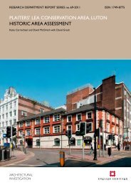
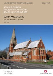
The face of the external wall is partially obscured in the data by the direct GPR wave,<br />
although some very near surface hyperbolic responses such as [GPR 1] and [GPR 2] are<br />
evident. It is unclear whether these represent undulations or defects in the stone surface<br />
or, perhaps more likely, a strong reflective target such as the head of a metal tie bar.<br />
Beyond this, few significant near-reflections are seen from between 0 and 5ns (~0 to<br />
0.25m) at which point an intermittent band of reflections (e.g. [GPR 3] on Line 1 and Line<br />
6) are found from between 6 and 12ns (~0.3 to 0.6m). In the upper survey area [GPR 3]<br />
demonstrates a less regular response with distinct gaps at [GPR 4, 5 and 6] which<br />
correspond with the approximate location of the rafter sockets cut into the inner face of<br />
the wall. The response to [GPR 6] is particularly well defined and it is notable that [GPR<br />
3] does not appear to extend W beyond the rafter socket over the door way to the gun<br />
deck parapet. The amplitude time slices show [GPR 3] as an area of high amplitude<br />
reflection consistent between 6 and 12ns (~0.3 to 0.6m) across the majority of the<br />
surveyed area with some suggestion of internal details (e.g. at [GPR 7-10]) together with<br />
the low amplitude response [GPR 11] to the W.<br />
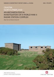
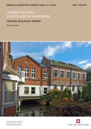
A well defined, linear reflector [GPR 12] is found consistently across all the profiles in the<br />
lower survey areas at 15ns (~0.75m) and, almost certainly, indicates the internal face of<br />
the wall (Figure 4). A similar response is found in upper survey area, although the anomaly<br />
is less well defined and, as would be expected, appears at later arrival time as the<br />
thickness of the wall increases towards the string corbell. For example, Line 1 shows the<br />
onset of [GPR 12] at 30ns (~1.5m) with breaks in the response related to the rafter<br />
sockets and a slighter earlier arrival time (27ns) to the W of [GPR 6]. Beyond [GPR 12]<br />
any recorded response is unlikely to be related to the structure of the wall and will be<br />
caused by internal reflections from within the Captain’s Chamber. This is illustrated by the<br />
profiles from the lower survey area which show a strong linear reflector [GPR 13]<br />
towards the end of the maximum recorded time window (50ns) between 3.5 to 5.5m.<br />
Given the increase of the radar wave-front velocity as it exits the wall this would place<br />
[GPR 13] at approximately 5m (50 – 15ns x 0.3m/ns) from the inner face, corresponding<br />
with a reflection generated by the metal framed display boards in this room.<br />
© ENGLISH HERITAGE 2 40-2013
A similar reflection is found at [GPR 14] in the profiles from the upper survey area,<br />
although this is constrained to a location between 7.5 and 9m and appears earlier in the<br />
time window (e.g. at ~30ns on Line 3). Again, taking into account the thickness of the wall<br />
indicated at this point and the increase in velocity once the wave-front has entered the<br />
room, this is likely to be caused by the rear wall of the passage-way immediately above<br />
the door-way to the gun deck parapet. Two notable hyperbolic reflections [GPR 15] and<br />
[GPR 16] occur at the internal aperture of the rafter sockets into the Captain’s Chamber.<br />
DISCUSSION<br />
The surface face of the wall appears sound from the GPR data within the first 0.25m, with<br />
the exception of the cover over the rafter sockets that may be reduced to ~0.1m from<br />
the response at [GPR 6]. This may indicate the generally sound nature of the facing ashlar,<br />
perhaps with some indication of repair work indicated by near-surface hyperbolic<br />
reflections (e.g. [GPR 4] and [GPR 5]). An area of more defined reflections then appears<br />
from between ~0.25 – 0.65m that is less regular in the upper area of the survey and may<br />
represent a layer of more disturbed rubble packing. From 0.65m to the onset of the<br />
reflection from the inner face of the wall (varying from ~1.5m at the top of the survey<br />
area to 0.8m in the lower area), there are relatively few reflectors suggesting a more<br />
sound inner face. However, the upper survey also shows areas of both high [GPR 17] and<br />
low [GPR 18] amplitude reflections in the amplitude time slices between 20 and 26ns<br />
(~1.0 to 1.3m) consistent with a degradation of the structural fabric in this region.<br />
The area surrounding the door-way to the gun deck parapet [GPR 11] contains few<br />
reflection events and, from the slightly earlier onset of the response to the inner face of<br />
the wall suggests, perhaps, this represents more sound fabric with a higher velocity.<br />
However, due to the presence of relatively few hyperbolic reflectors in this area the<br />
interpolated velocity field data suggests a lower average velocity (Figures 6 and 8(C)). The<br />
response to the rear face of the wall appears from 28ns (1.4m) over the door way [GPR<br />
19], although it is unclear why this remains persistent throughout the data. The increasing<br />
thickness of the wall may also account for the distinct variation in the response seen in the<br />
later reflections from 26ns (1.3m) onwards in the upper survey area. Above the line<br />
marked by [GPR 20] the response is attenuated but appears to reflect variations in the<br />
internal face of the wall, such as low amplitude response associated with the rafter<br />
sockets. However, below this line the reflections seem more likely to represent multiples<br />
generated from within the Captain’s Chamber rather than the structure of the wall itself<br />
and the extent of [GPR 19] below [GPR 20] is questionable.<br />
Individual hyperbolic responses identified in the GPR profiles were used to determine the<br />
variation of velocity throughout the data set (Figures 6 and 8(A)). The position of each<br />
response was recorded and interpolated across a 3D volume representing the full extent<br />
of the wall, although some degree of over/under shoot of the interpolation algorithm is<br />
evident due to the irregular distribution of the input velocity data. Relatively high, uniform<br />
velocities are found in the surface ashlar layer, but a much greater degree of variation<br />
from 0.3m onwards suggests the internal structure is less sound. A distinct area of lower<br />
velocity immediately beneath the string corbell between approximately 0.7 to 1.0m from<br />
the outer face of the wall may well indicate the location of significant water ingress.<br />
© ENGLISH HERITAGE 3 40-2013
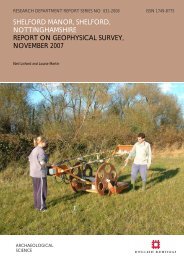
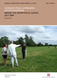
Figure 8 also shows the results from a synthetic model calculated to test the fidelity of the<br />
interpretation offered for the GPR data. The physical model (Figure 8(B)) is based on a<br />
section through the exterior wall containing sections of intact wall, an air-filled beam slot<br />
and an area of minor internal voiding. Dimensions have been chosen to match those at<br />
the site and a large, linear reflector has also been included to simulate the metal display<br />
found in the Captain’s chamber. A split-step 2D modelling algorithm following Bitri and<br />
Grandjean (1998) was used to calculate a synthetic profile for a 900MHz centre<br />
frequency antenna assuming the physical properties described by the model. The<br />
synthetic profile (Figure 8(C)) correlates well with the field data, with the intact sections<br />
of the wall demonstrating undisturbed, planar reflections from the expected interfaces<br />
within the model ([mod1] on Figure 8(C)).<br />
CONCLUSION<br />
The GPR survey has successfully recorded anomalies related to the varying thickness of<br />
the outer wall and the location of known defects due to visible beam sockets cut into the<br />
inner face. Additional variation in the structural integrity of the wall is suggested by the<br />
GPR data and has been verified against a synthetic model, allowing areas of possible<br />
voiding to be indentified. Velocity analysis, determined from hyperbolic responses within<br />
the survey data, suggests an area of possible water ingress identified through an area of<br />
lower velocity immediately below the string corbell. In addition, discrete very near surface<br />
hyperbolic responses may be associated with covered ferrous fixings, perhaps associated<br />
with historic repair work, as some corroded examples were observed during the survey<br />
which had caused visible damage to the surrounding ashlar.<br />
LIST OF ENCLOSED FIGURES<br />
Figure 1<br />
Figure 2<br />
Figure 3<br />
Figure 4<br />
Figure 5<br />
Figure 6<br />
Location of the GPR profiles superimposed over the photogrammetric<br />
plan of the east facing external elevation of the castle (1:50). The location<br />
of the castle is shown in inset OS map extract (1:2500) together with<br />
plans of the building indicating the location of the Captain’s Chamber (red<br />
line, 1:1500) and a schematic section through the North wall (1:30).<br />
Greyscale image of the GPR amplitude time slice from between 22 and<br />
24ns (1.1 to 1.2m) superimposed over the photogrammetric plan of the<br />
east facing external elevation of the castle (1:50).<br />
Selected GPR profiles from the upper survey area (see Figure 1 for<br />
location).<br />
Selected GPR profiles from the lower survey area (see Figure 1 for<br />
location).<br />
Greyscale images of the GPR amplitude time slices between 0.0 and 40ns<br />
(0.0 to 2.0m) from the survey area (1:100).<br />
False colour image of the interpolated velocity field data between<br />
approximate depth of between approximately 0.9 and 1.0m superimposed<br />
© ENGLISH HERITAGE 4 40-2013
over the photogrammetric plan of the east facing external elevation of the<br />
castle. The location of hyperbolic reflections used to create the velocity<br />
model are indicated by the + symbols and the full data set is shown in<br />
Figure 8(A) (1:50).<br />
Figure 7<br />
Figure 8<br />
Graphical summary of significant GPR anomalies superimposed over the<br />
photogrammetric plan of the east facing external elevation of the castle<br />
(1:50).<br />
Interpolated velocity field model (A) calculated from hyperbolic responses<br />
identified in the data set. Results from a synthetic model (B) to estimate<br />
the expected response of the exterior wall at <strong>Portland</strong> <strong>Castle</strong> consisting of<br />
a 0.25m exterior facing separated into a section with some minor voiding<br />
with the core (0 to 4.75m), a central 0.5m wide beam slot (5.0m) and a<br />
solid course without simulated defects (5.25 to 10m). A strong reflector is<br />
positioned between 3.0 and 8.0m simulates the metal display board within<br />
the Captain’s chamber. Values of resistivity (r), relative dielectric constant<br />
(e) and magnetic permeability (k) are shown for the target bodies in the<br />
model. The results of the synthetic GPR profile calculated from this model<br />
are shown in (C) and, despite the relative simplicity of the model and<br />
absence of noise, compare favourably with the recorded profiles (cf<br />
Figures 3 and 4). The time to depth conversion has been compensated for<br />
the transmission through air beyond 25ns with revised depths shown in<br />
brackets.<br />
© ENGLISH HERITAGE 5 40-2013
REFERENCES<br />
Bitri, A and Grandjean, G 1998 'Frequency-wavenumber modelling and migration of 2D<br />
GPR data in moderately heterogeneous dispersive media'. Geophysics, 46 (3),<br />
287-301.<br />
Cowles, M 2011 <strong>Portland</strong> <strong>Castle</strong>, Investigation of Water Ingress Through <strong>Castle</strong> Roof<br />
& Parapet Walls & Associated Remedial Works. Application for Class VI<br />
Consent Supporting Documentation, <strong>English</strong> <strong>Heritage</strong>.<br />
<strong>English</strong> <strong>Heritage</strong> 2008 Geophysical survey in archaeological field evaluation, second<br />
edition. Swindon, <strong>English</strong> <strong>Heritage</strong>.<br />
Linford, N 2004 'From Hypocaust to Hyperbola: Ground Penetrating Radar surveys<br />
over mainly Roman remains in the U.K.'. Archaeological Prospection, 11 (4),<br />
237-246.<br />
© ENGLISH HERITAGE 6 40-2013
PORTLAND CASTLE<br />
Selected GPR profiles, November 2012<br />
Figure 3<br />
Line 0<br />
S<br />
N<br />
0<br />
Line 3<br />
S<br />
N<br />
0<br />
Two-way travel time [ns]<br />
10<br />
0.45<br />
20<br />
0.9<br />
30<br />
1.35<br />
40<br />
1.8<br />
50<br />
2.25<br />
0.00 1.25 2.50 3.75 5.00 6.25 7.50 8.75<br />
Distance [m]<br />
Line 1<br />
S<br />
GPR6<br />
N<br />
0<br />
GPR4<br />
GPR5<br />
Depth [m]<br />
Two-way travel time [ns]<br />
10<br />
0.45<br />
20<br />
0.9<br />
30<br />
GPR14<br />
1.35<br />
40<br />
1.8<br />
50<br />
2.25<br />
0.00 1.25 2.50 3.75 5.00 6.25 7.50 8.75<br />
Distance [m]<br />
Line 4<br />
S<br />
N<br />
0<br />
Depth [m]<br />
Two-way travel time [ns]<br />
10<br />
20<br />
GPR3<br />
0.45<br />
0.9<br />
GPR16<br />
30<br />
40<br />
50<br />
GPR12<br />
GPR15<br />
1.35<br />
1.8<br />
2.25<br />
0.00 1.25 2.50 3.75 5.00 6.25 7.50 8.75<br />
Line 2<br />
S<br />
Distance [m]<br />
GPR1 GPR2<br />
N<br />
0<br />
Depth [m]<br />
Two-way travel time [ns]<br />
10<br />
0.45<br />
20<br />
0.9<br />
30<br />
1.35<br />
40<br />
1.8<br />
50<br />
2.25<br />
0.00 1.25 2.50 3.75 5.00 6.25 7.50 8.75<br />
Distance [m]<br />
Line 5<br />
S<br />
N<br />
0<br />
Depth [m]<br />
Two-way travel time [ns]<br />
10<br />
0.45<br />
20<br />
0.9<br />
30<br />
1.35<br />
40<br />
1.8<br />
50<br />
2.25<br />
0.00 1.25 2.50 3.75 5.00 6.25 7.50 8.75<br />
Distance [m]<br />
Depth [m]<br />
Two-way travel time [ns]<br />
10<br />
GPR10<br />
GPR7 GPR8<br />
GPR9<br />
0.45<br />
20<br />
0.9<br />
30<br />
1.35<br />
40<br />
1.8<br />
50<br />
2.25<br />
0.00 1.25 2.50 3.75 5.00 6.25 7.50 8.75<br />
Distance [m]<br />
Depth [m]<br />
Geophysics Team 2013<br />
Low<br />
High<br />
relative reflector strength
PORTLAND CASTLE<br />
Selected GPR profiles, November 2012<br />
Figure 4<br />
Line 6<br />
Line 22<br />
Line 12<br />
Line 28<br />
S<br />
N<br />
0<br />
S<br />
N<br />
0<br />
S<br />
N<br />
0<br />
S<br />
N<br />
0<br />
Two-way travel time [ns]<br />
10<br />
20<br />
GPR3<br />
GPR12<br />
30<br />
40<br />
GPR13<br />
50<br />
2.65 3.15 3.65 4.15 4.65 5.15<br />
Line 8<br />
Distance [m]<br />
0.45<br />
0.9<br />
1.35<br />
1.8<br />
2.25<br />
Depth [m]<br />
Two-way travel time [ns]<br />
10<br />
20<br />
30<br />
40<br />
50<br />
5.66 6.16 7.66<br />
Distance [m]<br />
Line 24<br />
0.45<br />
0.9<br />
1.35<br />
1.8<br />
2.25<br />
Depth [m]<br />
Two-way travel time [ns]<br />
10<br />
20<br />
30<br />
40<br />
50<br />
2.65 3.15 3.65 4.15 4.65 5.15<br />
Line 14<br />
Distance [m]<br />
0.45<br />
0.9<br />
1.35<br />
1.8<br />
2.25<br />
Depth [m]<br />
Two-way travel time [ns]<br />
10<br />
20<br />
30<br />
40<br />
50<br />
5.66 6.16 7.16<br />
Distance [m]<br />
Line 30<br />
0.45<br />
0.9<br />
1.35<br />
1.8<br />
2.25<br />
Depth [m]<br />
S<br />
N<br />
0<br />
S<br />
N<br />
0<br />
S<br />
N<br />
0<br />
S<br />
N<br />
0<br />
Two-way travel time [ns]<br />
10<br />
20<br />
30<br />
40<br />
50<br />
2.65 3.15 3.65 4.15 4.65 5.15<br />
Distance [m]<br />
Line 10<br />
0.45<br />
0.9<br />
1.35<br />
1.8<br />
2.25<br />
Depth [m]<br />
Two-way travel time [ns]<br />
10<br />
20<br />
30<br />
40<br />
50<br />
5.66 6.16 7.66<br />
Distance [m]<br />
Line 26<br />
0.45<br />
0.9<br />
1.35<br />
1.8<br />
2.25<br />
Depth [m]<br />
Two-way travel time [ns]<br />
10<br />
20<br />
30<br />
40<br />
50<br />
2.65 3.15 3.65 4.15 4.65 5.15<br />
Distance [m]<br />
Line 32<br />
0.45<br />
0.9<br />
1.35<br />
1.8<br />
2.25<br />
Depth [m]<br />
Two-way travel time [ns]<br />
10<br />
20<br />
30<br />
40<br />
50<br />
5.66 6.16 7.66<br />
Distance [m]<br />
0.45<br />
0.9<br />
1.35<br />
1.8<br />
2.25<br />
8.16<br />
Depth [m]<br />
S<br />
N<br />
0<br />
S<br />
N<br />
0<br />
S<br />
N<br />
0<br />
Two-way travel time [ns]<br />
10<br />
20<br />
30<br />
40<br />
50<br />
2.65 3.15 3.65 4.15 4.65 5.15<br />
Distance [m]<br />
0.45<br />
0.9<br />
1.35<br />
1.8<br />
2.25<br />
Depth [m]<br />
Two-way travel time [ns]<br />
10<br />
20<br />
30<br />
40<br />
50<br />
5.66 6.16 7.66<br />
Distance [m]<br />
0.45<br />
0.9<br />
1.35<br />
1.8<br />
2.25<br />
Depth [m]<br />
Two-way travel time [ns]<br />
10<br />
0.45<br />
20<br />
0.9<br />
30<br />
1.35<br />
40<br />
1.8<br />
50<br />
2.25<br />
0.0 1.0 2.0 3.0 4.0<br />
Distance [m]<br />
Depth [m]<br />
Low<br />
relative reflector strength<br />
High<br />
Geophysics Team 2013
PORTLAND CASTLE<br />
Interpolated velocity field data and Synthetic GPR model results<br />
Figure 8<br />
(A) Velocity field data<br />
(B) Model wall section<br />
0.0 - 0.1m 0.8 - 0.9m<br />
9<br />
9<br />
minor voiding beam socket solid wall<br />
14 9.5<br />
13 12.5<br />
9 10.5<br />
9<br />
13 14<br />
10<br />
9<br />
ρ = 1000, μ = 1, ε = 9 −> 14<br />
9<br />
9<br />
0.0<br />
1.0<br />
0.1 - 0.2m 0.9 - 1.0m<br />
0.2 - 0.3m 1.0 - 1.1m<br />
ρ = 100000000, μ = 1, ε = 1<br />
2.0<br />
3.0<br />
Depth [m]<br />
4.0<br />
0.3 - 0.4m 1.1 - 1.2m<br />
metal display planel<br />
ρ = 1000, μ = 1, ε = 6<br />
5.0<br />
0.0 2.5 5.0 7.5 10.0<br />
Distance [m]<br />
0.4 - 0.5m 1.2 - 1.3m<br />
(C) Synthetic GPR profile calculated from (A)<br />
0<br />
0. 5- 0.6m 1.3 - 1.4m<br />
0.6 - 0.7m 1.4 - 1.5m<br />
0.7 - 0.8m 1.5 - 1.6m<br />
Two-way travel time [ns]<br />
10<br />
20<br />
30<br />
40<br />
Distance [m]<br />
mod1<br />
0.45<br />
0.9<br />
1.35 (1.9)<br />
1.8 (3.4)<br />
50<br />
2.25 (4.9)<br />
0.0 2.5 5.0 7.5 10.0<br />
Depth [m]<br />
0.0 0.05 0.1 0.15<br />
Velocity [m/ns]<br />
Low<br />
relative reflector strength<br />
High<br />
Geophysics Team 2013
ENGLISH HERITAGE RESEARCH DEPARTMENT<br />
<strong>English</strong> <strong>Heritage</strong> undertakes and commissions research into the historic<br />
environment, and the issues that affect its condition and survival, in order to<br />
provide the understanding necessary for informed policy and decision making,<br />
for sustainable management, and to promote the widest access, appreciation<br />
and enjoyment of our heritage.<br />
The Research Department provides <strong>English</strong> <strong>Heritage</strong> with this capacity<br />
in the fields of buildings history, archaeology, and landscape history. It brings<br />
together seven teams with complementary investigative and analytical skills<br />
to provide integrated research expertise across the range of the historic<br />
environment. These are:<br />
* Aerial Survey and Investigation<br />
* Archaeological Projects (excavation)<br />
* Archaeological Science<br />
* Archaeological Survey and Investigation (landscape analysis)<br />
* Architectural Investigation<br />
* Imaging, Graphics and Survey (including measured and<br />
metric survey, and photography)<br />
* Survey of London<br />
The Research Department undertakes a wide range of investigative and<br />
analytical projects, and provides quality assurance and management support<br />
for externally-commissioned research. We aim for innovative work of the<br />
highest quality which will set agendas and standards for the historic<br />
environment sector. In support of this, and to build capacity and promote best<br />
practice in the sector, we also publish guidance and provide advice and training.<br />
We support outreach and education activities and build these in to our projects<br />
and programmes wherever possible.<br />
We make the results of our work available through the Research Department<br />
Report Series, and through journal publications and monographs. Our<br />
publication Research News, which appears three times a year, aims to keep<br />
our partners within and outside <strong>English</strong> <strong>Heritage</strong> up-to-date with our projects<br />
and activities. A full list of Research Department Reports, with abstracts and<br />
information on how to obtain copies, may be found on www.english-heritage.<br />
org.uk/researchreports<br />
For further information visit www.english-heritage.org.uk