grassington lead mines, north yorkshire a rapid ... - English Heritage
grassington lead mines, north yorkshire a rapid ... - English Heritage
grassington lead mines, north yorkshire a rapid ... - English Heritage

You also want an ePaper? Increase the reach of your titles
YUMPU automatically turns print PDFs into web optimized ePapers that Google loves.
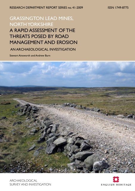
RESEARCH DEPARTMENT REPORT SERIES no. 41-2009 ISSN 1749-8775<br />
GRASSINGTON LEAD MINES,<br />
NORTH YORKSHIRE<br />
A RAPID ASSESSMENT OF THE<br />
THREATS POSED BY ROAD<br />
MANAGEMENT AND EROSION<br />
an ARCHAEOLOGICAL investigation<br />
Stewart Ainsworth and Andrew Burn
Research Department Report Series<br />
41- 2009<br />
GRASSINGTON MOOR LEAD MINES,<br />
NORTH YORKSHIRE<br />
A <strong>rapid</strong> assessment of threats<br />
posed by road management and erosion<br />
Stewart Ainsworth and Andrew Burn<br />
NGR: SE 0250 6650<br />
© <strong>English</strong> <strong>Heritage</strong><br />
ISSN 1749-8775<br />
The Research Department Report Series incorporates reports from all the specialist teams within the <strong>English</strong><br />
<strong>Heritage</strong> Research Department: Archaeological Science; Archaeological Archives; Historic Interiors Research and<br />
Conservation; Archaeological Projects; Aerial Survey and Investigation; Archaeological Survey and Investigation;<br />
Architectural Investigation; Imaging, Graphics and Survey, and the Survey of London. It replaces the former<br />
Centre for Archaeology Reports Series, the Archaeological Investigation Report Series and the Architectural<br />
Investigation Report Series.<br />
Many of these are interim reports which make available the results of specialist investigations in advance of full<br />
publication. They are not usually subject to external refereeing, and their conclusions may sometimes have to be<br />
modified in the light of information not available at the time of the investigation. Where no final project report<br />
is available, readers are advised to consult the author before citing these reports in any publication. Opinions<br />
expressed in Research Department reports are those of the author(s) and are not necessarily those of <strong>English</strong><br />
<strong>Heritage</strong>.<br />
Requests for further hard copies, after the initial print run, can be made by emailing:<br />
Res.reports@english-heritage.org.uk<br />
or by writing to:<br />
<strong>English</strong> <strong>Heritage</strong>, Fort Cumberland, Fort Cumberland Road, Eastney, Portsmouth PO4 9LD<br />
Please note that a charge will be made to cover printing and postage.<br />
© ENGLISH HERITAGE 41 - 2009
SUMMARY<br />
In 2008, a <strong>rapid</strong> assessment was undertaken of the historic <strong>lead</strong>-mining landscape on<br />
Grassington Moor in North Yorkshire (Scheduled Ancient Monument 31331). The mining<br />
remains, which cover an area of c. 2.5 sq km, reflect <strong>lead</strong>-mining and processing activities<br />
from at least the 17th century through to a peak in the mid 19th century, with widespread<br />
secondary re-working of spoil mounds, mainly for barytes and fluorspar, in the mid 20th<br />
century. The remains include extensive areas of shafts, built structures including mills,<br />
dressing floors and processing areas, waste mounds of varying size, water-management<br />
features and a network of roads. The assessment was prompted by concerns raised by<br />
the Yorkshire Dales National Park Authority relating to threats posed by unauthorised<br />
works undertaken on some of the roads, including the use of some spoil heaps to obtain<br />
resurfacing material. The assessment therefore focussed on the main road corridors<br />
through the Scheduled area, quantifying the impact of these works on the archaeological<br />
remains. In addition, analysis was undertaken of broader, landscape-scale threats, especially<br />
relating to fluvial dynamics, which also affect the complex and have in large part created<br />
the perceived need for the localised works on the roads. The assessment offered an<br />
opportunity to feed into a developing corpus of complementary research into upland<br />
<strong>lead</strong>-mining landscapes, which entails identification and measurement of threat, and the<br />
development of appropriate methodologies for recording and analysing the relationship<br />
between industrial landscapes and land management.<br />
CONTRIBUTORS<br />
The field survey was carried out by Stewart Ainsworth, a senior investigator within <strong>English</strong><br />
<strong>Heritage</strong> Research Department’s Archaeological Survey and Investigation team, with<br />
assistance from Andrew Burn who was working as a placement with the team as part<br />
of the EPPIC scheme sponsored by the Institute for Archaeologists. Abby Hunt assisted<br />
with construction of the GIS, and Jonathan Ainsworth (work experience student from the<br />
University of Chester) helped with the design of the database and inputting of data. New<br />
oblique aerial photographs were taken by Dave Macleod. The report was written and<br />
illustrated by Stewart Ainsworth and edited by Al Oswald and Tim Gates.<br />
ACKNOWLEDGEMENTS<br />
The author is grateful to Mike Gill (Recorder of the Northern Mine Research Society) for<br />
providing access to plans and records of the <strong>mines</strong> and for his help with numerous enquiries<br />
during the report writing. Thanks are also due to Miles Johnson of the Yorkshire Dales<br />
National Park Authority for providing access to maps and reports. We would also like to<br />
thank Lister Walmsley (local farmer) and Harvey Wiggins (game-keeper) for their practical<br />
help with access to the moors and farmland during the course of the assessment.<br />
ARCHIVE LOCATION<br />
The archive and copies of this report have been deposited in <strong>English</strong> <strong>Heritage</strong>'s public<br />
archive at the National Monuments Record Centre, Kemble Drive, Swindon SN2 2GZ.<br />
DATE OF SURVEY<br />
Field survey August 2008 – September 2008; aerial photographs November 2008<br />
CONTACT DETAILS<br />
<strong>English</strong> <strong>Heritage</strong>, 37 Tanner Row, York, YO1 6WP<br />
Stewart Ainsworth Tel. 01904 601936. Email: stewart.ainsworth@english-heritage.org.uk<br />
© ENGLISH HERITAGE 41 - 2009
CONTENTS<br />
1. Background to the assessment 1<br />
2. Aims and objectives of the assessment 7<br />
3. Approaches and methodology 11<br />
4. Road management and threats 16<br />
5. Presentation and categorisation of information 17<br />
5.1 GIS categorisation 17<br />
6. Results of the assessment 27<br />
6.1 The road network 27<br />
6.2 Assessment of the road corridors 45<br />
6.3 Assessment of spoil mounds within the Scheduled area as potential sources<br />
of material for road maintenance. 75<br />
6.4 Assessment of the threat posed by water erosion 79<br />
6.5 Main threat zones 85<br />
6.6 Evaluation of a suitable recording methodology to aid future management 96<br />
7. Conclusions 99<br />
7.1 Background drainage issues 99<br />
7.2 The roads, recent drains and other works to the road surfaces 101<br />
7.3 Potential sources of material for road maintenance 104<br />
7.4 Identification of wider threats 107<br />
7.5 Appropriate recording methods for future analyses 108<br />
7.6 Summary 113<br />
8. References 116<br />
Appendix 1: recommendations 120<br />
Appendix 2: gazetteer 123<br />
APPENDIX 3: CATEGORY 1: WORKS AND FEATURES RELATED TO MODERN<br />
AND HISTORIC DRAINAGE AND WATER MANAGEMENT 149<br />
APPENDIX 4: CATEGORY 2: WORKS AND FEATURES RELATING TO THE<br />
REMOVAL OF MATERIAL FROM SPOIL MOUNDS 151<br />
APPENDIX 5: CATEGORY 3: OTHER MODERN WORKS AND FEATURES<br />
AFFECTING THE SITE 153<br />
© ENGLISH HERITAGE 41 - 2009
contents<br />
Continued from previous page<br />
APPENDIX 6: POTENTIAL SOURCES OF MATERIAL FOR ROAD MAINTENANCE 155<br />
APPENDIX 7: erosion types 157<br />
APPENDIX 8: the road network 159<br />
APPENDIX 9: LOCATION OF FEATURES AND THEIR UIDs 160<br />
© ENGLISH HERITAGE 41 - 2009
LIST OF ILLUSTRATIONS<br />
Cover<br />
Section of Road 9 which was constructed as a raised causeway to allow the<br />
passge of rod-tracks (306) underneath<br />
Figure 1. Location of Grassington Moor <strong>lead</strong> <strong>mines</strong> 1<br />
Figure 2. Extent of the Scheduled Ancient Monument, showing roads and locations<br />
mentioned in the report 3<br />
Figure 3. Extracts from vertical aerial photographs showing changes resulting from the<br />
introduction of the Dales Chemical Company barytes plant in c.1956 5<br />
Figure 4. Orthorectified vertical aerial photography of the survey area 13<br />
Figure 5. Screen layout of the Access database 17<br />
Figure 6. Features defined by points, lines and polygons on the GIS 21<br />
Figure 7 Reduced-scale extracts from OS First Edition 6-inch scale maps 26<br />
Figure 8. The road network investigated 29<br />
Figure 9. Chronology of the road network investigated 31<br />
Figure 10. Example of Category 1a: deflection drain along Road 1 47<br />
Figure 11. Example of Category 1b: roadside drain along Road 1 47<br />
Figure 12. Example of Category 1c: metal-pipe drain along Road 1 48<br />
Figure 13. Example of Category 1d: wooden-trough drain along Road 1 48<br />
Figure 14. Category 1: modern drainage 49<br />
Figure 15. Example of Category 1e: artificial watercourse (298 - Duke's Water Course) 50<br />
Figure 16. Example of Category 1f: culvert 51<br />
Figure 17. Example of Category 1g: oblique aerial photograph showing standing water<br />
(artificial origins) 51<br />
Figure 18. Category 1: historic drainage and water management 53<br />
Figure 19. Example of Category 1h: natural watercourse (532) 54<br />
Figure 20. Category 1: natural water features 55<br />
Figure 21. Example of Category 2a: oblique aerial photograph showing historic extraction<br />
of material for mineral re-working at Turf Pits Mine (399) 57<br />
Figure 22. Example of Category 2b: recent extraction of material for road maintenance 58<br />
Figure 23. Category 2: works and features relating to the removal of material from<br />
spoil mounds 59<br />
Figure 24. Meerstone lying loose on the surface (336) 60<br />
Figure 25. Example of Category 2b: recent extraction of material for road maintenance 60<br />
Figure 26. Example of Category 3a: vehicle (type 1) 62<br />
Figure 27. Example of Category 3b: vehicle (type 2) 62<br />
Figure 28. Example of Category 3c: dumping/tipping 64<br />
Figure 29. Example of Category 3c: dumping/tipping 64<br />
Figure 30. Example of Category 3d: stone gathering 65<br />
Figure 31. Example of Category 3d: stone gathering 65<br />
Figure 32. Example of Category 3e: animal 66<br />
Figure 33. Example of Category 3f: visitor impacts 67<br />
Figure 34. Example of Category 3g: miscellaneous 68<br />
Figure 35. Example of Category 3h: removal of boulders 70<br />
Figure 36. Example of Category 3i: collapse 70<br />
Figure 37. Category 3a-i: other modern works and features affecting the site 71<br />
Figure 38. Example of Category 3j: pot-holes 72<br />
Figure 39. Example of Category 3k: scraping of road surfaces 72<br />
Figure 40. Category 3j-k: other modern works and features affecting the site 73<br />
© ENGLISH HERITAGE 41 - 2009
LIST OF ILLUSTRATIONS<br />
Continued from previous page<br />
Figure 41. Light coloured spoil mound in the centre of the photograph (311) 76<br />
Figure 42. Small spoil mound immediately to the left od the photographer's shadow (507) 76<br />
Figure 43. Potential sources of material for road maintenance 77<br />
Figure 44. Hydrological erosion types 78<br />
Figure 45. The area around the junctions of Roads 1, 7, 8 and 9 photographed after<br />
heavy rain in 1992 80<br />
Figure 46. Gulley erosion along Road 1 (8) 80<br />
Figure 47. Gulley erosion developing where leat (365) has been breached 81<br />
Figure 48. Sheet erosion where soils have been lost (272) 81<br />
Figure 49. Main threat zones 84<br />
Figure 50. Zone A. Oblique aerial photograph from the east in 2008. 85<br />
Figure 51. Zone B. Oblique aerial photograph from the south in 2008. 86<br />
Figure 52. Zone C. Oblique aerial photograph from the east in 2008. 87<br />
Figure 53. Zone D. Oblique aerial photograph from the <strong>north</strong> in 2008. 88<br />
Figure 54. Zone E. Oblique aerial photograph from the east in 2008. 89<br />
Figure 55. Zone F. Oblique aerial photograph from the east in 2008. 90<br />
Figure 56. Zone G. Oblique aerial photograph from the east in 2008. 91<br />
Figure 57. Zone H. Oblique aerial photograph from the south-east in 2008. 92<br />
Figure 58. Zone J. Oblique aerial photograph from the south-west in 2008. 92<br />
Figure 59. Zones K and N. Oblique aerial photograph from the east in 2008. 93<br />
Figure 60. Zone L. Oblique aerial photograph from the east in 2008. 95<br />
Figure 61. Zone M. Oblique aerial photograph from the <strong>north</strong> in 2008. 95<br />
Figure 62. Natural and artificial water features shown on the OS First Edition 6-inch<br />
scale maps (OS 1852; 1853) 98<br />
Figure 63. Graphical representations of the origins of roads and the impact of the<br />
modern works on the historic roads 103<br />
Figure 64. Sample LiDAR from the Miner-Farmer Landscapes of the North Pennines<br />
AONB project 111<br />
Figure 65. Index diagram showing the areas covered by Sheets 1-3 in Apendix 9 160<br />
Figure 66. Orthomap showing location of features and their UIDs - Sheet 1 161<br />
Figure 67. Orthomap showing location of features and their UIDs - Sheet 2 162<br />
Figure 68. Orthomap showing location of features and their UIDs - Sheet 3 163<br />
Figure 69. Sheet 1. Orthophotography 164<br />
Figure 70. Sheet 2. Orthophotography 165<br />
Figure 71. Sheet 3. Orthophotography 166
1. Background to the assessment<br />
In the summer of 2008, the Yorkshire Dales National Park Authority (YDNPA) notified<br />
<strong>English</strong> <strong>Heritage</strong> of its concerns regarding unauthorised works to the main track which<br />
crosses the Scheduled <strong>lead</strong>-mining complex on Grassington Moor in North Yorkshire.<br />
The national importance of the complex was recognised through its legal designation<br />
as a Scheduled Ancient Monument in 1999 (<strong>English</strong> <strong>Heritage</strong> 1999, national number<br />
31331). The modern works included removal of material from spoil mounds within the<br />
Scheduled area for resurfacing of the track. In the wake of this, discussions were held on<br />
site between Neil Redfern, representing <strong>English</strong> <strong>Heritage</strong>’s Regional Grants and Advice<br />
team for the Yorkshire and the Humber Region, the local farmer and a representative<br />
from the shooting estate - of which Grassington Moor forms part - to discuss<br />
management issues associated with the track and the issue of spoil removal.<br />
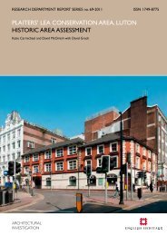
Grassington<br />
Moor<br />
Grassington Moor Lead Mines<br />
Threshfield<br />
Grassington<br />
Grimwith<br />
Reservoir<br />
River Wharfe<br />
Gargrave<br />
Bolton<br />
Abbey<br />
Land above<br />
Canal<br />
1400m<br />
1000m<br />
600m<br />
200m<br />
River Aire<br />
Skipton<br />
0 5km<br />
Figure 1: Location map.<br />
This plan is based on the OS map with the permission of Ordnance Survey on behalf of The Controller of Her Majesty’s<br />
Stationery Office, © Crown Copyright and database right 2009. All rights reserved. Ordnance Survey Licence 100019088.<br />
© ENGLISH HERITAGE<br />
<br />
41 - 2009
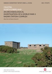
The main track under discussion is known, in part, as the Duke’s New Road. The majority<br />
of this is a former mine road, which runs <strong>north</strong>-eastwards from Yarnbury towards How<br />
Gill Nick (Figure 2). For ease of reference within this assessment, the roads and tracks<br />
across the Scheduled monument have been allocated road numbers, the Duke’s New<br />
Road itself being referred to henceforth as part of Road 1. Although the term ‘track’<br />
has been applied to the Duke’s New Road on modern Ordnance Survey (OS) mapping<br />
(OS 1978; 2005), it and most of the other routes examined are in fact deliberately made<br />
roads, many of 19th-century date and associated with the <strong>lead</strong> mining. Road 1 extends<br />
for approximately 3.3km (2 miles) to the <strong>north</strong>ern limit of the Scheduled area, and<br />
carries on <strong>north</strong>wards beyond. The Scheduled Monument covers two main Scheduled<br />
areas, one extending east from Yarnbury, and a second, larger area of the moor to the<br />
<strong>north</strong>; in addition there are a number of small satellite areas. Road 1 runs through both<br />
of the main areas, although a c. 0.5km-long section of it which connects the two is not<br />
Scheduled. This route provides access to the moor for shooting and associated land<br />
management and also provides access to the local farm (New House) via two other<br />
roads (Roads 2 and 4). In addition, it is is well-used by hikers and is the main access route<br />
for visitors to the historic remains themselves, as part of a way-marked ‘<strong>lead</strong>-mining trail’,<br />
with information boards which illustrate specific aspects of the industrial heritage. The<br />
southernmost section of Road 1, from Yarnbury to the Moor Wall (immediately west of<br />
the Cupola Smelt Mill at Cupola Corner), and Road 2 are shown as Public Rights of Way<br />
on OS small-scale mapping (OS 2005). The majority of the Scheduled area is designated<br />
as Access Land as defined by the Countryside and Rights of Way Act (2000), and<br />
ownership is a mixture of common and private land.<br />
During the discussions on site mentioned above, seven categories of works (listed in<br />
Section 4) were identified as having been undertaken without authorisation, but with the<br />
intention of repairing the access routes as part of a programme of regular maintenance<br />
(see Section 4). The development of a management plan (as originally proposed by the<br />
YDNPA) was also discussed. It was agreed that this was a desirable outcome and that<br />
such a plan could:<br />
• formulate strategies for the management of the Scheduled Monument<br />
• identify any particularly sensitive areas on or close to the roads<br />
• define the range and scope of maintenance works and where they could be<br />
undertaken<br />
• examine the possibility of using a number of spoil mounds to provide material<br />
for the future upkeep of the surfaces<br />
One of the principal aims of a management plan would be to provide a solid information<br />
base for the conservation and management of the Scheduled remains by the<br />
organisations with statutory responsibilities toward the historic environment (primarily<br />
<strong>English</strong> <strong>Heritage</strong> and the YDNPA). Another aim would be to assist the landowners,<br />
farmers and other stakeholders (such as the shooting estate) in maintaining appropriate<br />
access, while helping all concerned to identify and understand the most significant and<br />
© ENGLISH HERITAGE<br />
<br />
41 - 2009
402000<br />
468750<br />
This plan is based on the OS map with the permission of Ordnance<br />
Survey on behalf of The Controller of Her Majesty’s Stationery Office<br />
© Crown Copyright and database right 2009. All rights reserved.<br />
Ordnance Survey Licence number 100019088.<br />
How Gill Nick<br />
How Gill Mine<br />
35<br />
Byecliffe Hill<br />
Out Moor<br />
468000<br />
1<br />
Peru Mine<br />
401050<br />
467000<br />
466000<br />
Yarnbury<br />
465360<br />
34<br />
Old Moor Lane<br />
Low Grinding Mill<br />
33<br />
Duke’s Water Course<br />
1<br />
Bodin’s Mine<br />
Beever’s Mine<br />
Eller Beck<br />
36<br />
1<br />
New Pasture<br />
18<br />
4<br />
3<br />
Duke’s Water Course<br />
5<br />
Duke’s New Road<br />
16<br />
30<br />
Moor Wall<br />
17<br />
20<br />
22<br />
Moor Mill<br />
New Pasture Beck<br />
14<br />
Cockbur Mine<br />
2<br />
15<br />
West Turf Pits<br />
Mine<br />
13<br />
7<br />
Coalgrove Beck<br />
31<br />
37<br />
11<br />
32<br />
1<br />
1<br />
High Ringleton<br />
Mine<br />
Chatsworth<br />
Mine<br />
26<br />
Glory Mine<br />
Jone’s Mine<br />
High Grinding<br />
Mill<br />
Dales Chemical<br />
Company Plant<br />
21<br />
28<br />
27<br />
6<br />
23<br />
19<br />
Brake House Wheel<br />
High Smelt Mill<br />
Cupola Smelt Mill<br />
Lee’s Mine<br />
Byecliffe Mine<br />
29<br />
12<br />
Low Ringleton<br />
Mine<br />
8<br />
Brunt’s Mine<br />
Turf Pits Mine<br />
New Moss Mine<br />
24<br />
Moss Mine<br />
Taylor’s Mine Summer’s Mine<br />
Hebden Beck<br />
West Peru<br />
Mine<br />
Coalgrove Head<br />
Mine<br />
25<br />
High Winding House<br />
Coalgrove Beck Dam<br />
Coalgrove Beck<br />
Mine<br />
403000<br />
9<br />
New Peru Mine<br />
10<br />
Sarah’s Mine<br />
Old Moss Mine<br />
Duke’s High Water Course<br />
Duke’s Low Water Course<br />
403800<br />
1<br />
Principal access roads (with road number)<br />
Low Grinding Mill<br />
Principal topographic features, <strong>mines</strong>, and<br />
other named features referred to in the report<br />
34<br />
Other roads (with road number)<br />
Scheduled Ancient Monument<br />
0 1km<br />
Figure 2: Extent of the Scheduled Ancient Monument, showing roads and locations mentioned<br />
in the report. Based on OS 2008a, reduced from 1:10 000 scale.<br />
© ENGLISH HERITAGE<br />
<br />
41 - 2009
sensitive areas of the monument and the potential impacts of the works upon them. To<br />
further assist in the preparation of the management plan, Neil Redfern initiated a <strong>rapid</strong><br />
archaeological assessment of the affected areas by <strong>English</strong> <strong>Heritage</strong>’s Archaeological<br />
Survey and Investigation team, part of the organisation’s Research Department. The<br />
fieldwork for this <strong>rapid</strong> assessment was undertaken in August 2008 to Level 2 standard<br />
(as defined in Ainsworth et al 2007), and this report delivers its results. The historical<br />
names of <strong>mines</strong>, shafts etc used in this report have been largely abstracted from Gill<br />
(1993a) and OS mapping but for the sake of clarity (as terminology and spelling differ), in<br />
this report all have been suffixed with the term ‘mine’. Similarly, mining terms used have<br />
been taken from the National Monuments Record (NMR) Thesaurus of Monument Types<br />
(http://thesaurus.english-heritage.org.uk).<br />
Various studies and surveys have been undertaken previously of the historic mining<br />
remains on Grassington Moor (these are discussed in more detail in Section 6.6). The<br />
most recent is a study commissioned by the YDNPA in the light of concerns related to<br />
the hazards of open and uncapped shafts and pressure to quarry mining spoil for track<br />
maintenance. The aim of that study (Roe 2007) was to present an overview of the<br />
physical remains of the industrial activity with three principal objectives:<br />
• assess the current knowledge of the mining remains<br />
• identify survey strategies to enable the accurate location and interpretation of<br />
mining remains<br />
• develop a brief for a management plan of the area<br />
Roe’s assessment builds principally on research undertaken by Gill (1993a; 1998; 2000;<br />
2004) amongst others. Roe adequately summarises the historical background, and nature,<br />
accuracy and levels of completion of previous research, including field surveys, and it is<br />
not necessary to cover the same ground again in detail in this report. However, a brief<br />
summary of the basic chronology and current understanding derived from previous<br />
research is relevant at this point to contextualise some of the results and conclusions<br />
presented below (see Sections 6 and 7).<br />
Lead mining and processing on Grassington Moor may have been undertaken on a small<br />
scale before the 17th century, but the area was increasingly exploited through the 17th<br />
and 18th centuries, industrial activity reaching a peak in the 19th century. Yarnbury is<br />
thought to be the area of the earliest <strong>mines</strong> and during the first half of the 17th century<br />
mining extended onto the New Pasture to the east and onto Grassington Moor beyond.<br />
During the 17th and 18th centuries, the <strong>mines</strong> were regulated by a form of customary<br />
mining law which gave the miners small parcels of land to work, and up until the 1820s<br />
most mining took the form of shallow shafts. A few deeper shafts were dug between<br />
1774 and 1818 when the lease areas were increased, but most date from working under<br />
the direct control of successive Dukes of Devonshire (1818 to 1882). In 1797, a 2.5km<br />
long adit known as the Duke’s Level was dug from Hebden Gill (to the east) under<br />
the moor; it was also designed as an underground canal for transportation of ore and<br />
waste. This was not completed until 1830, when it reached Coalgrove Beck Mine. During<br />
© ENGLISH HERITAGE<br />
<br />
41 - 2009
1<br />
8<br />
9<br />
7<br />
1<br />
© <strong>English</strong> <strong>Heritage</strong> (NMR) RAF Photography<br />
82/RAF/1352 Frame no 0026, 31-DEC-55<br />
1<br />
8<br />
9<br />
7<br />
Dales Chemical<br />
Company Plant<br />
1<br />
© YDNPA. MAL/68045/Frame no 106 13-JUN-1968<br />
1<br />
Principal access roads<br />
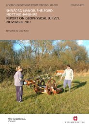
Figure 3: Extracts from vertical aerial photographs showing the changes resulting from the introduction<br />
of the Dales Chemical Company barytes plant in c. 1956. In the 1955 photograph the large 19thcentury<br />
spoil mounds are relatively undisturbed. By 1968, however, the impact of large-scale mineral<br />
reclamation from the large spoil mounds is evidenced by the light-coloured scars which show areas<br />
where spoil has either been removed or re-worked. The line which runs diagonally from bottom centre<br />
to top right in the 1968 photograph is a gas pipeline (41) which was laid in the late 1960s.<br />
© ENGLISH HERITAGE<br />
<br />
41 - 2009
this period there were significant improvements in pumping and winding, the creation<br />
of centralised dressing floors, and the construction of roads which linked the various<br />
components. Three smelt mills existed within the Scheduled area: High Mill, Moor Mill,<br />
and Cupola Mill, which was built last, in 1792. The Duke’s New Road was constructed<br />
in 1825-6, connecting the <strong>mines</strong> at Yarnbury to the rest of the moor. Significant<br />
technological advances included the introduction in 1821 of a system of rods, ropes<br />
and levers to provide pumping and winding for several separate <strong>mines</strong> on the <strong>north</strong> of<br />
the moor, powered by a waterwheel called the Brake House Wheel. Three reservoirs<br />
harnessing water for power and processing were constructed between 1821 and 1826,<br />
along with a network of water courses. Mining started to decline from the mid-1840s<br />
and in 1882 the last mine was abandoned. After this, there appears to have been little<br />
activity until 1915, when re-working of the spoil mounds for barytes and fluorspar began<br />
on a relatively small scale, but this venture ultimately proved unsuccessful and production<br />
ceased in 1927. During the Second World War, the moor was used for military training.<br />
The establishment of the Dales Chemical Company barytes plant on the site of the High<br />
Grinding Mill c. 1956 seems to mark the turning point from earlier, small-scale, episodic<br />
re-working of the spoil mounds to intensive, large-scale reclamation. This transition<br />
is well-illustrated on vertical aerial photography taken around that period (Figure 3).<br />
Earlier photographs taken in 1946 and 1954 suggest that there had been minimal<br />
disturbance to the larger shaft mounds and the wider landscape between those dates,<br />
but by 1968, when the next systematic aerial photography was undertaken, there had<br />
been significant reclamation at most of the larger shaft mounds and new roads created<br />
for access to the mounds. There had also been extensive changes around the High<br />
Grinding Mill at Coalgrove Beck, where the main processing plant was located, although<br />
by 1968 it had been partly demolished. Similar extensive changes can be seen in the<br />
Yarnbury area around the Low Grinding Mill, Beever’s Mine, Byecliffe Mines and along the<br />
contour towards How Gill Mine to the <strong>north</strong>-west. The Dales Chemical Company plant<br />
finally closed in 1964. The process of re-working mineral-rich waste, which has had a<br />
considerable impact on the physical remains of the earlier industrial activity, finally ceased<br />
in the late 1970s (Gill,1993a; 1998; 2000; 2004; Meridian Airmaps 1968; RAF 1946; 1952;<br />
1954; 1955; Roe 2003; 2007; <strong>English</strong> <strong>Heritage</strong> 1999).<br />
© ENGLISH HERITAGE<br />
<br />
41 - 2009
2. Aims and objectives of the assessment<br />
The primary purpose of the 2008 assessment was to provide <strong>English</strong> <strong>Heritage</strong>’s Regional<br />
Grants and Advice team with up-to-date information and understanding concerning the<br />
location, extent, context and potential impact of the types of modern works already<br />
undertaken on the road network, as well as assessing the desirability or otherwise of<br />
continuing such works as part of a future management regime. For this requirement, it<br />
was only necessary to investigate the principal road corridors (see below) and therefore<br />
the smaller, satellite Scheduled areas to the east and the bulk of the Scheduled area to<br />
the west of the roads were not included.<br />
Secondarily, the assessment aimed to contribute to a developing corpus of recent<br />
complementary archaeological research that will further the understanding and recording<br />
of upland <strong>lead</strong>-mining landscapes, including quantification and measurement of threat,<br />
and the development of appropriate methodologies for recording and analysing the<br />
relationship between industrial landscapes and land management (Ainsworth 2006;<br />
2008; 2009; Ainsworth and Hunt 2007; Barnatt and Penny 2004; Hunt and Ainsworth<br />
2007; in prep.). This research sits within a wider framework of initiatives relating to the<br />
management, understanding and recording of the historic environment: <strong>Heritage</strong> at Risk<br />
(<strong>English</strong> <strong>Heritage</strong> 2008a); the Regional Research Frameworks for the North-East and<br />
North-West of England (Petts and Gerrard 2006; Brennand 2006); the Countryside<br />
Survey (Topping et al 2006); <strong>Heritage</strong> Counts (<strong>English</strong> <strong>Heritage</strong> 2008b); Conservation<br />
Principles Policies and Guidance (<strong>English</strong> <strong>Heritage</strong> 2008c); and climate-change agenda<br />
(<strong>English</strong> <strong>Heritage</strong> 2008d).<br />
This report therefore presents the specific results of the assessment on Grassington<br />
Moor and proposes a series of recommendations aimed at informing a future strategy<br />
for addressing the issues that have been raised relating to the roads and spoil-mound<br />
management within the Scheduled area. It also places the results of the assessment<br />
within the context of the development of appropriate research- and conservation-led<br />
methodologies for recording upland <strong>lead</strong>-mining landscapes elsewhere in England.<br />
Although the 2008 assessment was prompted by the impacts of works on Road 1, to<br />
have undertaken an assessment which focussed exclusively on that route in isolation<br />
would have failed to integrate the management of this arterial track with the network<br />
of other tracks and roads which historically linked other components of the Grassington<br />
Moor mining complex, some of which also still provide access for shooting and land<br />
management. It was therefore considered necessary to assess the road network as a<br />
whole. Some drainage works had been undertaken along the edges of the roads, so it<br />
was also necessary to examine a margin alongside each road to assess potential impacts<br />
on archaeological features bordering the routes themselves. The width of this corridor<br />
varied according to the nature of the archaeological remains encountered. Also, in order<br />
to be able to quantify and assess the impact of past, and possible future, exploitation of<br />
spoil mounds as sources of resurfacing material, those most accessible from the roads<br />
were assessed and categorised according to their significance, although wider areas<br />
were examined to establish a reliable context. This assessment, as well as addressing<br />
specific issues, can be used along with other studies (including Roe 2003; 2007) to inform<br />
© ENGLISH HERITAGE<br />
<br />
41 - 2009
the development of future strategies for the Scheduled site through a multi-partner<br />
approach. With all this in mind, the assessment had the following objectives:<br />
• Objective 1. Rapidly identify and assess the actual and potential impact of the<br />
works associated with the maintenance of the road surfaces and digging of<br />
drains along, and in close proximity to, the roads through the Scheduled <strong>lead</strong>mining<br />
area on Grassington Moor.<br />
• Objective 2. Rapidly identify and assess the severity of damage to spoil mounds<br />
and associated remains within the Scheduled area caused by the removal of<br />
material for road maintenance.<br />
• Objective 3. Rapidly identify other specific threats pertinent to the management<br />
and conservation of the access roads and remains within their penumbra.<br />
• Objective 4. Rapidly identify any deposits of waste material within the Scheduled<br />
area which could feasibly be used in the future as sources of material or road<br />
maintenance, and quantify the potential impact of such use.<br />
• Objective 5. Rapidly identify any other threats to the historic remains.<br />
• Objective 6. Develop, trial and report on a recording methodology based on<br />
orthophotography, mapping-grade GPS (Global Positioning System) and a GIS<br />
(Geographical Information System) database, both to underpin the delivery<br />
of Objectives 1 - 5 and to provide a baseline survey for the development of<br />
a management plan and any future assessments on Grassington Moor (see<br />
Sections 3 and 5).<br />
In order to fulfil the needs of <strong>English</strong> <strong>Heritage</strong> it was not considered necessary at this<br />
stage to undertake a detailed survey (at Level 3, as defined in Ainsworth et al 2007) of<br />
the areas of concern, which would have included a detailed description and interpretation<br />
of individual archaeological features and detailed analysis of the chronology of the<br />
complex as a whole. Only limited consultation of secondary sources and mapping has<br />
been undertaken to help provide context where deemed appropriate to achieving the<br />
objectives above.<br />
In addition to the site-specific aims above, the assessment of elements of the Grassington<br />
complex has also provided the opportunity to feed into and develop guidelines for<br />
survey methodologies which may be applied to other upland industrial landscapes.<br />
<strong>English</strong> <strong>Heritage</strong>’s Research Department is currently involved in more wide-ranging<br />
research into the development of new analytical and recording methodologies for upland<br />
<strong>lead</strong>-mining landscapes and the development of models for future work. Two current<br />
<strong>English</strong> <strong>Heritage</strong> projects which have been designed to promote standards for this<br />
type of research are currently in progress: ‘Scordale Lead Mines’ (in partnership with<br />
Defence Estates/MoD), and ‘Miner-Farmer landscapes of the North Pennines Area of<br />
Outstanding Natural Beauty’ in partnership with the North Pennines AONB Partnership,<br />
Natural England and the Environment Agency (Ainsworth 2006; 2008; 2009; Ainsworth<br />
© ENGLISH HERITAGE<br />
<br />
41 - 2009
and Hunt 2007; Hunt and Ainsworth 2007; in prep.; Lane and Dugdale 2006). <strong>English</strong><br />
<strong>Heritage</strong>’s wider research has a range of aims, of which the most relevant in the context<br />
of the assessment of Grassington are:<br />
• increase the understanding and record of the historic environment<br />
• contribute to the conservation and management of the historic environment<br />
• develop new research methodologies applicable to upland <strong>lead</strong>-mining<br />
landscapes<br />
• contribute to natural environment and climate-change studies<br />
This broader research programme integrates field evidence-based analysis and recording<br />
of the historic environment with the quantification of threats from factors such as land<br />
management practices and natural processes. At the heart of the research is a need to<br />
increase the understanding of the dynamic interaction between the historic or cultural<br />
environment (of which industry, farming and associated settlement are key components)<br />
and the natural environment. It is intended that this research will offer insights into the<br />
role of human activities in contributing to fluvial erosion, peat loss and other phenomena<br />
in upland areas which are usually considered to be indicators of climate-change. As an<br />
integral aspect of this, the research is developing and testing new methodologies for the<br />
identification, recording and analysis of evidence for mining activities and land use. This<br />
includes the use of high-resolution digital orthophotography, hyper-spectral bandwidth<br />
aerial photography, terrestrial geophysics, LiDAR (Light Detection and Ranging),<br />
landform modelling, vegetation pattern analysis and soil science (Ainsworth 2008; 2009).<br />
The disparate datasets are being brought together through GIS, with specially designed<br />
recording structures and methods, to set standards and offer guidelines for future work.<br />
To set the work at Grassington into this wider context, it is worth outlining some of the<br />
preliminary findings of the research already undertaken by <strong>English</strong> <strong>Heritage</strong> in the North<br />
Pennines. It is clear that a combination of inter-related variables affects the movement of<br />
water (termed ‘hydrological flowpaths’) through <strong>lead</strong>-mining landscapes and the ways in<br />
which this movement impacts on both the land surface itself and archaeological remains<br />
which are either immediately above or below the surface. These variables include<br />
climate, parent material, topography, vegetation cover and human activity. The last of<br />
these is particularly relevant where the cultural remains form a dense and extensive<br />
matrix over the existing fluvial geomorphology, as is commonly the case in <strong>lead</strong>-mining<br />
landscapes. The distinctive surface characteristics of these landscapes include extensive<br />
areas of large, stony spoil mounds, dense concentrations of surface deposits such as<br />
ore-dressing waste and residual material with variable-density sediment properties,<br />
ranging from fine silt particles to boulders, and redundant water-management features<br />
such as artificial channels (often known as leats or goyts) and reservoirs. The surface<br />
remains, depending on their complexity, size and density, can act either as barriers or<br />
transport agents in a hydrological flowpath. The remains also have different waterretention<br />
characteristics depending on their particle size (in other words, some forms of<br />
waste such as ‘slimes’ retain water, whilst similar-sized deposits of stone chippings act as<br />
© ENGLISH HERITAGE<br />
<br />
41 - 2009
deflection barriers). Understanding the specific preferential flowpaths adopted by water<br />
through a given industrial complex and natural fluvial features is necessary to understand<br />
potential erosion threats and thus to formulate and enact proposals for conservation and<br />
management. In <strong>lead</strong>-mining landscapes, the potential for erosion must be coupled with<br />
the presence of contaminants such as <strong>lead</strong> and other related minerals. Depending on a<br />
number of variables, including volumes of both water and contaminants and the duration<br />
of contact between them, there is always the potential for localised water retention<br />
and flowpaths of small, concentrated areas of pollution to impact on much larger areas,<br />
especially where the fluvial dispersal systems reach into the wider river-catchment<br />
systems. Therefore, research which furthers the understanding of the location and<br />
character of the waste materials and the form of the local water dispersal mechanisms is<br />
arguably just as important as recording the industrial infrastructure of mining complexes<br />
in terms of developing strategies for the conservation of <strong>lead</strong>-mining landscapes.<br />
Early analysis of the fieldwork from the Scordale project, combined with reconnaissance<br />
elsewhere in the North Pennines suggests that <strong>lead</strong>-mining landscapes go through three<br />
basic fluvial stages;<br />
• Fluvial Stage 1 - the fluvial geomorphology of the landscape before mining takes<br />
place (which already may not be ‘natural’, sometimes being partly the product of<br />
earlier land management).<br />
• Fluvial Stage 2 - active management of, and changes to the pre-existing fluvial<br />
landscape to deliver water for waterwheels (to provide power for a range of<br />
equipment) and post-extraction processes associated with mining, such as<br />
washing of mined ore and so on. This includes episodic changes to the matrix<br />
over the life of mining operations.<br />
• Fluvial Stage 3 – following final abandonment of the <strong>mines</strong> and associated<br />
activities. During this phase features which functioned and were actively<br />
maintained in Fluvial Stage 2 are no longer managed. This results in a gradual,<br />
quasi-natural reversion to the dominant hydrological flowpaths determined by<br />
Fluvial Stage 1.<br />
Although <strong>English</strong> <strong>Heritage</strong>’s 2008 assessment at Grassington had limited aims and<br />
objectives, it provides a useful comparator, as another upland <strong>lead</strong>-mining landscape<br />
with erosion and land-use issues similar to those encountered in the other project areas.<br />
Grassington in particular offered an opportunity to examine the relationship between<br />
ad hoc works carried out in Fluvial Stage 3 which are intended to control or provide<br />
solutions to erosion problems caused by gradual change in hydrological pathways. To<br />
allow the complex relationship between water-based erosion and surface <strong>lead</strong>-mining<br />
remains to be quantified, a classification of applicable hydrological erosion types has been<br />
produced (see Section 5.1.7). The results can, in due course, be fed into the predictive<br />
models which are being developed through the Scordale and Miner-Farmer projects, for<br />
identifying future threats in extensive, <strong>lead</strong>-mining landscapes, large parts of which do not<br />
have statutory protection.<br />
© ENGLISH HERITAGE<br />
10<br />
41 - 2009
3. Approaches and methodology<br />
Knowledge of <strong>lead</strong>-mining complexes is often dominated by studies of historical<br />
documents and technological developments, supplemented by precisely targeted<br />
surveys and more rarely excavations of obvious surface features, particularly buildings,<br />
and below-ground workings. While ruined mills, shafts, adits, spoil mounds and so<br />
on are highly visible components of the industrial activity, it is often the less obvious<br />
features which provide evidence for the many and varied activities that were associated<br />
with the complexes. These less obvious features include slight earthworks, timberbuilt<br />
components, mobile or short-lived machinery, deposits relating to dressing and<br />
sorting processes, traces of short-lived or episodic mining and re-working, modified<br />
water-flow patterns, variations in the mineralogical qualities of waste material, and so<br />
on. Such ephemeral features tend to be unrepresented, or less clearly represented, in<br />
written and cartographic sources and, partly as a consequence of that, have received<br />
less attention from field researchers, an observation which applies not only to the early<br />
periods of mining, but also to the larger-scale 19th- and 20th-century activities. Despite<br />
their potential archaeological importance, ephemeral features, often being hard to<br />
recognise, can also be easily damaged. Equally important, <strong>lead</strong> mining cannot be divorced<br />
from other aspects of landscape change which occur in the same geographical and<br />
geological contexts - such as settlement and agriculture - from the prehistoric period<br />
onwards, as well as other industrial and extractive activities. Furthermore, early mining<br />
is generally less well understood, leaving a gap in the understanding of the complexities<br />
and development through time of mining landscapes. However, the perception that the<br />
later intensive and extensive <strong>lead</strong>-mining and mineral reclamation, dating to the 19th and<br />
20th centuries, has entirely destroyed the evidence for earlier activities (whether related<br />
to mining or not) is one that can be challenged on both the evidence of fieldwork in<br />
Scordale (Hunt and Ainsworth in prep.), as well as observations made during the 2008<br />
assessment at Grassington. Indeed, a similar point has already been made in the light of<br />
earlier research at Grassington (Roe 2003, 69). Therefore, systematic, holistic analytical<br />
survey of the surface remains is vital in developing an evidence-based understanding of<br />
the totality of the <strong>lead</strong> industry, and its socio-economic context, through time. However,<br />
analytical survey of large areas of complex <strong>lead</strong>-mining landscapes can be time consuming<br />
and the most effective survey equipment and software costly; the lack of such research<br />
therefore continues to inhibit the formulation of long-term land and cultural heritage<br />
management strategies.<br />
The choice of method for any field survey project or assessment (including <strong>lead</strong> mining)<br />
has to be geared towards addressing the primary aims and objectives of the project.<br />
To guide both individuals and organisations in making such choices, <strong>English</strong> <strong>Heritage</strong> has<br />
published a set of guidelines defining three ‘levels’ of survey which are appropriate to<br />
different aims (Ainsworth et al 2007). This framework has been used to structure the<br />
approaches and methods of the two <strong>English</strong> <strong>Heritage</strong> Research Department projects<br />
(noted above) investigating <strong>lead</strong>-mining landscapes that are currently under way in the<br />
<strong>north</strong> of England: Scordale, and the Miner-Farmer landscapes of the North Pennines<br />
AONB. Both these cover extensive mining landscapes (Scordale covers c. 4 sq km, whilst<br />
the Miner-Farmer project covers c. 50 sq km) and for both a Level 2, 1:2 500 mappingscale<br />
method based on a combination of orthophotography and LiDAR (described<br />
© ENGLISH HERITAGE<br />
11<br />
41 - 2009
elow) has been adopted. These projects are specifically aimed at research into the<br />
recording and analysis of large <strong>lead</strong>-mining landscapes and integration with threat and<br />
land-management issues, as well as developing appropriate methodologies for their<br />
recording and analysis. This research is particularly aimed at informing heritage strategies<br />
in relation to 'protected landscapes' within National Parks and Areas of Outstanding<br />
Natural Beauty, where many <strong>lead</strong>-mining remains are still not recorded in sufficient<br />
detail to inform management and do not have statutory protection. Some of the issues<br />
encountered in these landscapes apply to Grassington Moor, particularly levels of threat<br />
from fluvial mechanics (see below), lack of appropriate surveys and information base, and<br />
the complexity of the remains. The needs of the assessment at Grassington therefore<br />
also offered an additional opportunity to further enhance the understanding of the<br />
broader relationship between the archaeology of complex <strong>lead</strong>-mining landscapes and<br />
factors that contribute to erosion of and threat to the historic environment, whilst also<br />
responding to a specific local need. It also offered the opportunity to test some of the<br />
methodological and research strands developed for the Scordale and Miner-Farmer<br />
projects, particularly in relation to the issues surrounding the design of an appropriate<br />
GIS database, identification of threats and appropriate methods of recording. From all<br />
points of view, it was important to adopt a methodology which allowed identification,<br />
understanding and analysis with adequate confidence, combined with <strong>rapid</strong>, efficient<br />
recording on which management decisions could be based. Consequently, for this<br />
assessment, a Level 2 approach was appropriate, using techniques which are derived<br />
from and integrate with the other research into <strong>lead</strong>-mining landscapes being carried<br />
out by <strong>English</strong> <strong>Heritage</strong>. The method employed at Grassington uses field observation<br />
and analysis, but using large-scale, digital aerial orthophotography as the map base,<br />
supplemented by Global Positioning Systems (GPS) mapping-grade survey equipment<br />
where necessary. The field data was then brought together within a GIS database to<br />
aid retrieval, spatial analysis and management (this method is described in more detail<br />
below).<br />
Fortuitously, the majority of the fieldwork at Grassington was undertaken in a period<br />
of continuous, heavy rain. This provided an opportunity to assess the impacts that<br />
high-volume water flows have on both the roads and the archaeological remains, and<br />
to observe complex hydrological flowpaths in operation. In addition to observation<br />
and analysis in the field, the assessment employed a number of digital approaches and<br />
applications:<br />
Orthophotography (rectified, digital, vertical colour aerial photography).<br />
This imagery (at 25cm resolution supplied by NextPerspectives TM as part of the<br />
Pan Government Agreement) has been corrected to OSGB36 geodetic datum:<br />
it has a quoted positional accuracy of +/-1.5m RMSE (Infoterra 2008), and is<br />
accurate for 1:2 500 scale mapping within the OS National Grid. In other words,<br />
it provides a computer-rectified and scaled photograph of the ground surface,<br />
sometimes termed an ‘orthomap’, to the same accuracy as the OS mapping. Even<br />
small features c. 1m across can be easily identified on the images (dependent on<br />
the vegetation coverage). As a high proportion of features were visible on this<br />
photography (and are therefore by default already mapped into the OS National<br />
Grid by virtue of the rectification process), this alleviated the need for time-<br />
© ENGLISH HERITAGE<br />
12<br />
41 - 2009
consuming ground survey. As a base-map, the orthophotograph also makes visual<br />
re-identification of features easier for management purposes (Figure 4 and Figures<br />
65-71 in Appendix 9).<br />
468000<br />
467000<br />
466000<br />
465400<br />
401100<br />
402000<br />
403000 404000<br />
0 1km<br />
Figure 4: Orthorectified, vertical aerial photography of the survey area. The original 'as<br />
photographed' colour saturation and contrast settings have been refined to produce colour<br />
levels where <strong>lead</strong>-mining waste and re-worked areas can be easily identified (grey and white).<br />
The part panel at the top-centre shows the original unaltered image tones - see Section 6.6.<br />
Licensed to <strong>English</strong> <strong>Heritage</strong> for PGA, through Next Perspectives. TM<br />
© ENGLISH HERITAGE<br />
13<br />
41 - 2009
Mapping-grade GPS (Trimble GeoXT hand-held equipment).<br />
This instrument receives differential corrections through the EGNOS (European<br />
Geostationary Navigation Overlap Service) satellite, enabling real-time corrections to<br />
OSTN02/OSGM02 transformations. This is generally accurate to better than 1m<br />
and has proved to be adequate for 1:2 500 scale mapping within the OS National<br />
Grid; it can thus be directly imported into the GIS alongside the orthophotography<br />
and base mapping. The GPS software (Fastmap) provides feature-coded mapping<br />
of features directly onto a base-map and/or the orthophotography for direct realtime<br />
comparison with features on the ground. It allows direct data entry at the<br />
same time onto a database programme designed by <strong>English</strong> <strong>Heritage</strong> for recording<br />
feature information for import into the GIS. At Grassington, the GPS was only<br />
used to map features when they were not visible on the orthophotography.<br />
Digital ground photography (Canon G5 digital camera).<br />
A digital camera was used to compile a photographic database of damage at time<br />
of survey. The photographic archive is linked to the GIS<br />
GIS (ESRI ArcView GIS based on Microsoft Access database software).<br />
GIS and database software have been used to develop a geo-referenced database<br />
for recording upland <strong>lead</strong>-mining landscapes and threats for the Miner-Farmer and<br />
Scordale projects. This has been further tailored to the specific requirements of the<br />
Grassington assessment. The categories of information recorded are outlined below<br />
(see Section 5 and Figure 5). This GIS approach facilitates the collation and retrieval<br />
of geo-referenced graphical and textual information in a single environment, for<br />
example maps, aerial photography, ground survey and photography, alongside textual<br />
observations on threat and damage. The use of GIS also permits ‘geo-landscape<br />
modelling’, that is, the structuring of analytical queries concerning the relationships<br />
between the database information and the spatial data in three dimensions.<br />
The recording method adopted at Grassington comprised a walk-over of the road<br />
corridors by two field archaeologists, equipped with readily-available, digitally-rectified<br />
orthophotography at 1: 2 500 mapping scale, mapping-grade GPS and digital cameras.<br />
This allowed the fieldworkers to observe both in overview and at close range, and then<br />
record on site, archaeological features, their chronological relationships and context,<br />
as well as any associated threats. The orthophotography was used directly in the field<br />
during this process as an accurate map base on which archaeological features could<br />
easily be identified and <strong>rapid</strong>ly recorded against the orthophoto background by traced<br />
centre-point, line, or polygon, and additional database information recorded either on<br />
the GPS data-forms or in notebooks. Smaller features which were not easily identifiable<br />
on the imagery (such as deflection drains and artefacts) were recorded using the GPS.<br />
The fieldwork took eight days in total spread over three weeks. Over 500 features which<br />
contributed to the final analysis were recorded at a basic level using the methodology<br />
described. The collation of the results comprised the second, desk-based stage when<br />
data was transferred to the database and GIS. Each relevant feature was allocated a<br />
unique number and categories of information were recorded which were relevant to<br />
the assessment (see Section 5). The GIS and database structures developed for this<br />
assessment were designed both to record the categories of information deemed relevant<br />
to this project, and also be usable as a dataset capable of analysis within the wider GIS<br />
© ENGLISH HERITAGE<br />
14<br />
41 - 2009
framework being established for <strong>lead</strong>-mining landscapes elsewhere as part of the <strong>English</strong><br />
<strong>Heritage</strong> research agenda. This approach is aimed at standardising and facilitating the<br />
mapping, categorisation, quantification and retrieval of threat types, erosion types, and<br />
monument types on a large landscape scale.<br />
The structure of this assessment was primarily aimed at providing an up-to-date<br />
information base which will permit field archaeologists, land managers and those with<br />
statutory responsibility for protection of the historic environment to formulate an<br />
appropriate strategy for the future understanding, protection and management of<br />
the nationally important <strong>lead</strong>-mining landscape at Grassington. The methodological<br />
approaches adopted for this were designed also to test their usefulness for other similar<br />
<strong>rapid</strong> assessments of <strong>lead</strong>-mining landscapes and associated threats elsewhere.<br />
The products of this assessment comprise three components: the GIS, the Access<br />
database that underpins it, and this report. The latter provides the background to the<br />
need for the assessment, the methodology adopted, and also sets out the findings and a<br />
number of recommendations.<br />
© ENGLISH HERITAGE<br />
15<br />
41 - 2009
4. Road management and threats<br />
The lack of any record of the exact locations of the various unauthorised works and<br />
any precise quantification of their impacts has inhibited evidence-based analysis of<br />
developments to date. This is compounded by the lack of an overall survey of the<br />
remains against which to assess the context of the modern works. The recording<br />
methodology adopted for this assessment qualifies and quantifies the consequences of<br />
the various works by accurately locating them all and establishing a basic categorisation.<br />
The types of works which were identified by Neil Redfern (<strong>English</strong> <strong>Heritage</strong> Regional<br />
Advice and Grants team) prior to <strong>English</strong> <strong>Heritage</strong>’s 2008 survey as having had an impact<br />
on Road 1 and the other roads are as follows;<br />
i<br />
ii<br />
iii<br />
iv<br />
v<br />
vi<br />
vii<br />
Infilling of holes on the road surfaces.<br />
Scraping and levelling of the surfaces of the roads.<br />
Cutting of gullies at the edges of the roads to channel water run-off.<br />
Making low ridges with adjacent shallow gullies on the upslope side across<br />
the roads to divert water off the surface and prevent it being washed<br />
away.<br />
Cutting of drainage gullies alongside the roads to prevent water washing<br />
across the surface.<br />
Using boulders to consolidate the sides of watercourses where there is<br />
severe erosion.<br />
Use of material from the spoil mounds for road repair and maintenance<br />
including i, ii, and iv above.<br />
During the course of the assessment a number of threats to the road corridors which<br />
have not been recognised previously were identified. Although a range of perceived<br />
general threats to the Scheduled monument has already been presented (Roe 2007, 2),<br />
it was outside the scope of that study to quantify them in detail. In this assessment by<br />
<strong>English</strong> <strong>Heritage</strong>, a distinction has been made between threats resulting from deliberate<br />
human intervention, which includes the seven categories noted above, and damage<br />
resulting from quasi-natural erosion (see Sections 5.1.6 and 5.1.7).<br />
© ENGLISH HERITAGE<br />
16<br />
41 - 2009
5. Presentation and categorisation of information<br />
5.1 GIS categorisation<br />
The categorisation adopted for this assessment is designed to deliver the objectives<br />
defined in Section 2, by identifying specific cases as well as highlighting broader trends<br />
pertinent to informing immediate and long-term management along the road network.<br />
Numbers in brackets in this report, for example (99), relate to the relevant Unique<br />
Identification (UID) number (see 5.1.1 below, Figure 5, and Appendices 2 and 9) in the<br />
GIS. The database and GIS have been constructed to include the following information.<br />
5.1.1 Feature number<br />
Each record has a Unique Identification (UID) number, which may relate to any feature<br />
or area of features, whether archaeological, natural or modern; the sequence follows<br />
no geographical or thematic pattern. The numbers are not linked to the National<br />
Monuments Record (NMR) or Historic Environment Record (HER) numbering systems.<br />
5.1.2 Feature type<br />
For archaeological features, the NMR Thesaurus of Monument Types terms have been<br />
used. Where modern works and erosion have been recorded, a series of terms has been<br />
adopted based on established recording mechanisms and ongoing research into <strong>lead</strong>mining<br />
landscapes (see Sections 5.1.6 and 5.1.7).<br />
Figure 5: Screen layout of the Access database.<br />
© ENGLISH HERITAGE<br />
17<br />
41 - 2009
5.1.3 Feature name<br />
This is used where a feature has a traditional name, for example Feature 298 has<br />
traditionally been called the Duke’s Water Course. This association is not exhaustive or<br />
prescriptive and has been used simply to assist identification of links between features.<br />
There is also a facility to record an alternative name for a feature where appropriate.<br />
5.1.4 National Grid Reference (NGR)<br />
OS grid references accurate to the nearest metre are provided for each feature.<br />
5.1.5 Road number<br />
For ease of identification, each road that passes through the Scheduled area has been<br />
allocated its own Road number (Roads 1 to 37) as well as a UID within the GIS.<br />
5.1.6 Types of works and threats<br />
As set out below, the different types of modern works along the road corridors<br />
pertinent to this assessment have been broken down into three categories using, and<br />
wherever necessary refining, models established from the <strong>Heritage</strong> at Risk study (<strong>English</strong><br />
<strong>Heritage</strong> 2008a), the current Miner-Farmer Project (Ainsworth 2008), the Countryside<br />
Survey (Topping et al 2006), and the Scheduled Monuments at Risk pilot project (Fearn<br />
and Humble 2003; 2004).<br />
Category 1: works and features related to modern and historic water-management.<br />
1a: Deflection drain. This type of drain consists of two main components, a raised<br />
earthwork barrier (on average 0.3m high), with an adjacent channel of similar depth cut<br />
into the road on the upslope side (although some are simple gullies), intended to divert<br />
water and thus prevent it from washing away the road surface. The barrier is usually<br />
composed of material dug from the channel, but sometimes of material imported from<br />
elsewhere. On average the barriers and drains together are 1.5m wide overall and span<br />
the full width of the roads (in other words, they are 2.5m long on average). These are<br />
the works identified in Section 4iv.<br />
1b: Roadside drain. These drains are characterised by artificial channels of varying width<br />
and depth, but on average they are no more than 1m wide and 0.3m deep, dug alongside<br />
the roads (some by machine, others apparently by hand). They are intended to collect<br />
run-off from the deflection drains and other sources and/or to prevent water from<br />
washing onto the road surface by redirecting it along the road edge. In some cases,<br />
original drains associated with the mining drainage (which functioned in a similar way)<br />
have been re-used. These two slightly different deployments were initially identified<br />
separately as having an impact on the road (see Section 4iii and 4v), but their physical<br />
form and location are similar in terms of potential impacts and therefore these have been<br />
brought together in a single category in this assessment.<br />
© ENGLISH HERITAGE<br />
18<br />
41 - 2009
1c: Metal-pipe drain. Instances where metal pipes, with slots cut along the length of their<br />
upper sides, have been sunk into the road surface to take water from the surface and<br />
redirect it to the side. Thus, these drains function similarly to the gullies of the deflection<br />
drains (Type 1a) and the wooden troughs (Type 1d).<br />
1d: Wooden-trough drain. This type of drain consists of a narrow trough (averaging 0.3m<br />
wide and 0.2m deep) constructed of nailed timber planks, which has been sunk into<br />
the surface of the road, spanning most of its width, to take water from the surface and<br />
redirect it to the side. Thus, these are in effect a wooden equivalent of the metal-pipe<br />
drain (Type 1c).<br />
1e: Artificial watercourse. Historic water-management features, primarily leats and drainage<br />
channels, which are contemporary components of the historic mining landscape, and<br />
which now have potential for causing damage to tracks through overflow when subject<br />
to high volumes of water. Mostly, these watercourses comprise narrow channels with<br />
upcast banks on one or both sides; they range from obvious, prominent earthworks<br />
to shallow, barely perceptible channels. Some are long, extending well outside the<br />
Scheduled area, while others are much shorter, for example connecting small ponds<br />
within dressing floors.<br />
1f: Culvert. Instances of where watercourses and drains were carried under the roads<br />
as part of the water management contemporary with the mining operations, usually in<br />
stone-lined channels. They often conduct water back into natural watercourses (Type 1h).<br />
None appear to have been constructed as part of modern road maintenance, although<br />
some may have been re-cut, piped or blocked.<br />
1g: Standing water (artificial origins). Features such as reservoirs and ponds which were<br />
designed to store bodies of water within the mining areas and have potential for causing<br />
damage to roads and other features through overflow and seepage, or when breached.<br />
1h: Natural watercourse. Natural water features such as stream courses, which have<br />
the potential to cause damage to roads and other features, particularly after heavy<br />
precipitation episodes.<br />
1i: Standing water (natural origins). Features such as ponds and bogs which have the<br />
potential for causing damage to roads and other features when maximum saturation is<br />
achieved and water is released.<br />
Category 2: works and features relating to the removal of material from spoil mounds<br />
2a: Mineral re-working. Instances of where there is evidence for the re-working of spoil<br />
mounds for the reclamation of minerals, such as barytes, fluorspar or lower-grade<br />
<strong>lead</strong>, as part of the historic development of the Scheduled monument. Some of these<br />
comprise large areas where widespread evidence of re-working has been grouped<br />
together for recording purposes, and which have a variety of impacts on the mining<br />
remains, whilst other have been recorded separately, such as individual, or small clusters<br />
of ore-dressing mounds.<br />
© ENGLISH HERITAGE<br />
19<br />
41 - 2009
2b: Removal of material from spoil mounds for road resurfacing. Areas where there is<br />
evidence that spoil mounds may have been used in the recent past as possible sources<br />
of material for road repairs and maintenance. These are the modern works identified in<br />
Section 4vii above.<br />
Category 3: other modern activities affecting the site<br />
3a: Vehicle (type 1). Places where vehicles used for shooting parties, recreation and<br />
associated activities (typically 4x4 and road cars) may have caused damage.<br />
3b: Vehicle (type 2). Places where heavy vehicles used mostly for land management,<br />
farming and road repairs (tractors, trailers and mini-diggers etc) may have caused<br />
damage.<br />
3c: Dumping/tipping. Areas where modern waste, including agricultural debris, building<br />
material and domestic rubbish has been dumped.<br />
3d: Stone gathering. Instances of where dumps of stones (including building stone) indicate<br />
that the integrity of archaeological or architectural features elsewhere may have been<br />
compromised by their removal.<br />
3e: Animal. Instances of where animal activity is causing damage to the archaeological<br />
resource close to roads.<br />
3f: Visitor impacts. Instances of where damage close to the roads is being caused by<br />
visitors.<br />
3g: Miscellaneous. Other impacts on the road; for example, where cattle-grids have been<br />
sunk into the track surfaces to restrict animal movement, and where a gas pipeline has<br />
been cut through the landscape.<br />
3h: Removal of boulders. Specific areas from where large stones or boulders have been<br />
removed, usually for re-use in nearby anti-erosion measures. These are the modern<br />
works identified in Section 4vi above.<br />
3i: Collapse. Places where structures have collapsed as a result of neglect/erosion.<br />
3j: Pot-holes. Small depressions on track surfaces, usually caused by a combination of<br />
vehicle movement, loose material, and standing water. In this assessment only large<br />
examples have been recorded. The hollows tend to fill with water, causing further<br />
erosion when this overflows. Infilling these holes constitutes the modern works identified<br />
in Section 4i above.<br />
3k: Scraping of road surfaces. Areas along the roads where there is evidence of either<br />
mechanised grading or similar works to the road surface. These are the modern works<br />
identified in Section 4ii above.<br />
© ENGLISH HERITAGE<br />
20<br />
41 - 2009
5.1.7 Types of hydrological erosion<br />
An attempt has been made to identify the main types of hydrological erosion which<br />
affect the integrity of the archaeological resource along the road corridors. Although<br />
erosion may be deemed to be a natural process, there is clearly a complex relationship<br />
between the artificial water-management features related to the historic <strong>lead</strong> mining, and<br />
the natural drainage pattern. Whether erosion is caused by human activities or natural<br />
processes, both can clearly have a destructive impact on the archaeological resource<br />
through either the loss of the structural integrity of standing structures and other cultural<br />
material, or the removal of environmental evidence and archaeological deposits. It has<br />
been demonstrated through the 2008 assessment that even small artificial interventions<br />
such as inappropriately positioned deflection drains may have longer-term erosion<br />
implications (this is further discussed below).<br />
468000<br />
467000<br />
466000<br />
465400<br />
401100<br />
402000<br />
403000 404000<br />
0 1km<br />
Scheduled Ancient Monument<br />
Area (polygon)<br />
Linear feature (line)<br />
Individual feature (point)<br />
Figure 6: Features defined by points lines and polygons on the GIS (see Appendix 9 for largerscale<br />
orthomaps and UIDs). Based on orthorectified, vertical aerial photography of the survey<br />
area. Licensed to <strong>English</strong> <strong>Heritage</strong> for PGA, through Next Perspectives. TM<br />
© ENGLISH HERITAGE<br />
21<br />
41 - 2009
A survey which was undertaken in response to the destruction of structures by<br />
water erosion at the Hilton and Murton Scheduled <strong>lead</strong> <strong>mines</strong> at Scordale in Cumbria<br />
(Ainsworth 2006; Ainsworth and Hunt 2007; Hunt and Ainsworth 2007; in prep.) began<br />
to identify the broad impact of active hydrological erosion on <strong>lead</strong>-mining remains (see<br />
below). This work has helped develop a categorisation of the types of hydrological<br />
erosion and their interactions with <strong>lead</strong>-mining remains as part of the GIS for the Miner-<br />
Farmer landscapes of the North Pennines AONB project (Ainsworth 2008, 2009;<br />
Ainsworth and Hunt 2007). This database has been adapted for the <strong>rapid</strong> assessment at<br />
Grassington. Whilst this categorisation follows established models for classifying water<br />
erosion on soil surfaces and natural topography (for example, Charlton 2008, 42-51),<br />
<strong>English</strong> <strong>Heritage</strong>’s previous fieldwork has demonstrated that it is equally applicable to<br />
the complex micro-topography of historic mining landscapes. This study is being further<br />
explored and refined through the Miner-Farmer project.<br />
Hydrological Erosion Type 1: Surface splash.<br />
This erosion is characterised by the detachment of small particles of material by the<br />
impact of raindrops. When the volume of rainfall increases, small particles of soil, finegrained<br />
waste, etc can be moved by sheet erosion (Hydrological Erosion Type 4) as<br />
water runs off solid surfaces (such as roads, paths, dressing-floors etc). This type of<br />
erosion is more powerful on steeper slopes, and/or where there is little vegetation cover.<br />
On slopes, this can soon start to coalesce into channel/rill flows (Hydrological Erosion<br />
Type 2) if left unmanaged.<br />
Hydrological Erosion Type 2: Channel/rill.<br />
This erosion is typified by shallow, meandering channels, which often cover extensive<br />
areas, sometimes as part of a complex, anastomosed (that is, interconnected) matrix of<br />
erratically directed and variable volume flows. It consists of small, ephemeral flowpaths<br />
which function both as sediment source and delivery system, and flows can become<br />
concentrated. Rills tend to wind their way around even quite slight archaeological features<br />
(such as low earthworks and dumps of hard waste) rather than break through them.<br />
They continually change in response to morphological changes which they themselves<br />
generate and can thus be unpredictable. They can carry significant volumes of finegrained<br />
waste, and where channels become concentrated, gulley erosion (Hydrological<br />
Erosion Type 3) can result if left unmanaged. Although not as immediately obvious as<br />
gulley erosion, nevertheless rill (and inter-rill) erosion is capable of transporting large<br />
soil particles and even small rock fragments (Charlton 2008, 45). As the sediment<br />
load increases, the ability of the flowing water to detach more sediment decreases. In<br />
periods of heavy rainfall, these can amalgamate to become sheets of water with different<br />
sediment loadings. When the transport capacity of the flow is exceeded, deposition<br />
starts and outwash fans are deposited. Channel/rills generally vary in size and width from<br />
5cm to 30cm (Knighton 1998).<br />
Hydrological Erosion Type 3: Gulley.<br />
This erosion exists where the force of water action is predominantly downwards and is<br />
caused by a combination of high flow speed and high volume. It usually produces narrow,<br />
© ENGLISH HERITAGE<br />
22<br />
41 - 2009
steep-sided channels which gradually widen over time as the sides repeatedly become<br />
undermined and eventually collapse in a similar way to stream erosion (Hydrological<br />
Erosion Type 5). This type of flow is capable of dislodging and moving larger stone sizes<br />
and when left unchecked can <strong>lead</strong> to collapse of structures. Channels with steep gradients<br />
are prone to this form of erosion, as can be artificially dug channels, particularly in the<br />
lower reaches of a network if left unmanaged. Most erosion occurs at the head of the<br />
gulley, and under certain circumstances the erosion can retreat <strong>rapid</strong>ly upslope and a large<br />
amount of material can be removed over a short period of time, even during a single<br />
run-off event. This type of erosion is not necessarily caused by continuous water flows,<br />
but can be episodic and when developed can allow <strong>rapid</strong> transportation of water and<br />
sediment. Gullies are generally more permanent features than channel/rills and can be<br />
classed as gullies for most purposes from depths of 0.5m upwards (Charlton 2008, 46).<br />
Hydrological Erosion Type 4: Sheet.<br />
This type of erosion is typified by run-off after periods of heavy rain where channels do<br />
not exist to concentrate the flow, or have become overloaded due to the high volume<br />
of water, and/or where groundwater saturation levels are high. Sheet erosion can be<br />
focussed on areas where there has already been significant loss of surface soil and<br />
vegetation. It can be exaggerated on surfaces clogged with fine sands and silts (such as<br />
slimes) where the infiltration rate is lowered. It is a continuous, sheet-like movement of<br />
shallow water, although depths and erosion/transportation capabilities can be variable as<br />
a result of micro-scale variations in the underlying surfaces. Sheet erosion tends to move<br />
small and medium grain-sized material, most effectively on steep slopes and bare soil<br />
surfaces, and can spread over wide areas (Charlton 2008, 46 - quoting Morgan 2005).<br />
Hydrological Erosion Type 5: River/stream.<br />
This is defined as continuous flow along a linear depression, usually as part of a wider,<br />
naturally-formed drainage pattern. Erosion is mostly vertical, but several variables affect<br />
the erosive capabilities. Most erosion occurs during times of heavy rainfall when faster<br />
water can carry a larger sediment load, including larger pebbles and even boulders.<br />
During periods of alternating drought and heavy precipitation, flows can be episodic and<br />
powerful and the erosion and undermining of banks can <strong>lead</strong> to channel widening and<br />
scouring dependent on the resistance of the parent material (Charlton 2008, 5-9).<br />
Hydrological Erosion Type 6: Flash.<br />
Usually episodic in nature, resulting from heavy and prolonged periods of precipitation<br />
where especially large amounts of water rush down stream channels, gullies etc and<br />
through sheer volume and power can wash away upstanding features and archaeological<br />
levels in a single event.<br />
Other physical weathering factors such as freeze/thaw, wind, chemical reaction and<br />
so on, will also affect the severity of the above six erosion types on the archaeological<br />
structures and deposits. No attempt has been made to record every single instance of<br />
environmental erosion and its contributory elements; that is beyond the scope of this<br />
assessment. However, indicative trends can be identified using the methodology adopted.<br />
© ENGLISH HERITAGE<br />
23<br />
41 - 2009
5.1.8 Date of survey<br />
The date at which the record was made, as a benchmark for monitoring change.<br />
5.1.9 Risk to archaeological integrity<br />
Risk has been defined in the Scheduled Monuments at Risk study (Darvill and Fulton<br />
1998, Glossary xlv) as ‘the idea that there is a chance or possibility of danger, loss or<br />
injury or some other adverse consequences as a result of natural processes or the<br />
intentional or unintentional actions of individuals or groups. More particularly, the degree<br />
of risk that any monument may be exposed to is the combination of the probability<br />
or frequency of the occurrence of a recognised hazard in relation to the magnitude<br />
of the consequences.’ For this assessment, risk has been based on factors defined by<br />
the above and three other related archaeological studies that embody risk and threat<br />
issues; <strong>Heritage</strong> at Risk (<strong>English</strong> <strong>Heritage</strong> 2008a); Scheduled Monuments at Risk (Fearn and<br />
Humble 2003; 2004); Countryside Survey (Topping et al 2006).<br />
Risk to the archaeological integrity of any feature investigated as part of this assessment<br />
has been categorised as low, medium or high in relation to the incidence of damage to<br />
this specific feature or likely impact on others (see Appendices 3-5).<br />
• Low - little or no direct risk to archaeological features. Monitoring may be<br />
required in the medium term.<br />
• Medium - some minimal damage to archaeological features, or potential<br />
for damage. Monitoring may be required in the short to medium term.<br />
• High - significant damage to archaeological features, or potential for<br />
damage. Further discussion about the activity and its impact may<br />
be required in the short term to mitigate against further compromise of the<br />
integrity of the archaeological resource.<br />
5.1.10 Potential sources of material for road repairs and building of deflection barriers<br />
Because one of the objectives of the assessment was to establish if any of the spoil<br />
mounds within the Scheduled area could be utilised in the future as sources of material<br />
for resurfacing of the roads and tracks (see Sections 2 and 4), a simple classification has<br />
been established in response (see Appendix 6).<br />
• A - indicates that this feature/group of features could be considered as a source<br />
of material without significantly compromising the archaeological resource.<br />
• B - indicates that this feature/group of features may be perceived to be already<br />
irrevocably modified to the point where it has little archaeological value and thus<br />
has potential for continued use as a source of resurfacing material.<br />
• C - indicates that the archaeological significance of this feature/group of features<br />
is such that it should not be used as a supply source<br />
© ENGLISH HERITAGE<br />
24<br />
41 - 2009
5.1.11 Description<br />
A free-text description of the feature/group of features with any supporting sources<br />
(where appropriate).<br />
5.1.12 Photographs<br />
Where photographs have been taken of a feature, they have been referenced to the GIS<br />
by the same UID.<br />
5.1.13 Evidence<br />
Principal source of evidence for the feature (terms as defined in the NMR Monument<br />
Thesaurus of Monument Types).<br />
5.1.14 Period<br />
Period assigned to the feature (as defined in the NMR Thesaurus of Monument Types).<br />
5.1.15 Century<br />
Century assigned where appropriate (as defined in the NMR Thesaurus of Monument<br />
Types).<br />
5.1.16 Class<br />
Monument class (as defined in the NMR Thesaurus of Monument Types).<br />
5.1.17 Vulnerability code<br />
Primary and secondary threats to which a feature or group is vulnerable as defined in<br />
Scheduled Monuments at Risk and Countryside Survey guidelines (Fearn and Humble 2003;<br />
Topping et al 2006).<br />
5.1.18 Condition<br />
Condition of a feature or group of features as defined in Scheduled Monuments at Risk<br />
guidelines (Fearn and Humble 2003).<br />
5.1.19 Erosion classification<br />
Main erosion to which a feature or group of features is susceptible to (see Appendix 7).<br />
A summary of the results of the assessment and the conclusions that can be drawn are<br />
presented below (Sections 6 and 7 respectively).<br />
© ENGLISH HERITAGE<br />
25<br />
41 - 2009
Yorkshire 116. Surveyed 1844-50. Published 1852<br />
0 1km<br />
Yorkshire 134. Surveyed 1848-50. Published 1853<br />
Figure 7: Reduced-scale extracts from OS First Edition 6-inch scale maps which cover the<br />
assessment area (OS 1852; 1853).<br />
© ENGLISH HERITAGE<br />
26<br />
41 - 2009
6. Results of the assessment<br />
As outlined in Section 2, this assessment had five key objectives. The results pertaining<br />
to each objective are presented below (Sections 6.2 - 6.5). However, before the results<br />
can be seen in the context of the relationship between the main road network and the<br />
mining areas, it is necessary to provide a brief account of the roads investigated and their<br />
development (Section 6.1). It is clear from the evidence on the ground that there are<br />
numerous other routes, such as less obvious roads, tramways, hollow ways and paths,<br />
associated with the development of the mining industry over a considerable period of<br />
time, still surviving within the Scheduled area. However, providing a fuller analysis of the<br />
evolution of the access and transport system lies outside the scope of this report. In line<br />
with the aims and objectives of this <strong>rapid</strong> assessment, only the principal road corridors<br />
have been investigated, although where appropriate, spur-roads have been included<br />
where there is potential for impacts associated with them on the main corridors.<br />
6.1 The road network<br />
The aim of this section is to simply characterise the development of the road network<br />
through the Scheduled monument so that the access infrastructure can be viewed as a<br />
whole. It is not a detailed history and chronology of every road and track and is designed<br />
to help put into context the results and conclusions presented in Sections 6 and 7.<br />
A number of hollow ways can be identified which suggest that various routes existed<br />
across this landscape prior to the infrastructure of built roads depicted on the 19th and<br />
early 20th-century OS mapping (1852; 1853; 1891; 1893-4; 1909; 1910). The routes of<br />
some of these earlier hollow ways can be seen to be cut by the line of, and therefore<br />
must predate, the Duke’s New Road (Road 1a), which was built in 1825-6 (Gill 1993a,<br />
53), and some can be traced through the New Pasture. Elsewhere, a number of<br />
other hollow ways are also cut by and pre-date the infrastructure of built roads which<br />
developed from the early 19th century onwards. Some of these hollow ways ascend onto<br />
the Out Moor from the eastern end of Old Moor Lane beyond the Moor Wall, with a<br />
number of short sections and minor branches surviving amongst the later mine workings<br />
on the moor. It has been suggested by Gill (1993a, 71) that the mining spread onto<br />
the Out Moor in 1731, that by the 1750s the mineral vein pattern was well known, and<br />
that a new generation of larger <strong>mines</strong> began to appear in 1751 and 1752, at Coalgrove<br />
Head and Coalgrove Beck. Whilst some of these hollow ways undoubtedly relate to<br />
this expansion of mining on the Out Moor, some may be even earlier and relate to<br />
undocumented activity and access. From the mid-18th century onwards, it is likely that<br />
a number of roads, tracks and paths would have linked the various <strong>mines</strong> and mining<br />
operations (such as mills) on the Out Moor and the routes through the New Pasture<br />
at Old Moor Lane and Yarnbury. With the expansion of the <strong>mines</strong> in the early 19th<br />
century also came the introduction of mechanisation, and this prompted the building<br />
of a network of properly engineered and well-drained roads between the major shafts,<br />
dressing floors and the Cupola Smelt Mill (Gill, 1993a, 37). This network remained largely<br />
unchanged until the mid-20th century. Aerial photography indicates that extensive reworking<br />
of the spoil mounds for barytes and fluorspar took place in the 1950s and ‘60s,<br />
mostly by the Dales Chemical Company between c. 1956 and 1964 (Gill 1993a, 137-8,<br />
143). This led to heavy re-use of many of the earlier roads, and the creation of new<br />
© ENGLISH HERITAGE<br />
27<br />
41 - 2009
ones to provide access to spoil mounds (RAF 1952; 1954; 1955; Meridian Airmaps 1968;<br />
OS 1972a). It is likely therefore that many of the formally constructed roads within the<br />
Scheduled area have a long and complex chronology. Since the final period of processing,<br />
mainly at Beever’s Mine in the late 1970s (Gill 1993a, 139), the roads have largely been<br />
used for access for land management and farming activities.<br />
To aid the understanding of this assessment, the roads which are currently in use, used<br />
recently, or shown on the latest 1:10 000 OS digital mapping (OS 2008a), are listed<br />
below by individual road number and are briefly described. They are noted in this report<br />
as ‘Active’ if showing evidence of recent use and ‘Inactive’ if they are no longer normally<br />
used. Where these have been given a feature number as part of the GIS gazetteer, this<br />
is shown in brackets. If modern works have been carried out along their route, this is<br />
noted. Unless stated otherwise, most of the roads described below fit into the early<br />
19th-century context noted above (see Figures 8 and 9).<br />
Road 1: Active (358). Modern works undertaken.<br />
Although the current road from Yarnbury to the How Gill Mine area is the main artery<br />
of the road network, it is actually composed of three distinct sections of differing dates.<br />
For the purposes of this assessment, Road 1a applies to the longest section, running<br />
for c. 2.4km (73% of the total length of Road 1 from Yarnbury to How Gill Mine) from<br />
Yarnbury to Byecliffe Mine, the southernmost section of which is historically called the<br />
Duke’s New Road (OS 1853; 1978). Road 1b applies to the section from Byecliffe Mine<br />
<strong>north</strong>wards for c. 400m (12% of the total length of Road 1). Road 1c continues the line<br />
west from Road 1b and runs through the Scheduled area for c. 500m (15% of the total<br />
length of Road 1) before continuing <strong>north</strong>wards beyond How Gill Mine. The majority of<br />
the modern drainage works are along Road 1.<br />
Road 1a: Active. Modern works undertaken.<br />
The expansion of the industry in the early 19th century demanded the construction of<br />
an easier route onto the Out Moor, to replace the Old Moor Lane, which was steep in<br />
sections and more difficult to negotiate. As a result, the Duke’s New Road was built. Gill<br />
gives two dates for construction, 1827 (Gill 1993a, 37), and the winter of 1825/6 for ‘The<br />
New Road’ from Yarnbury to Coalgrove Beck (ibid, 53) which is likely to be the more<br />
accurate date (Gill pers. comm.). To maintain easy gradients, an embankment (499) was<br />
built across the valley of the New Pasture Beck in 1828 (ibid 37, 53). This embankment<br />
is shown on the OS (1853) 6-inch scale map and evidently forms part of a dam for a<br />
reservoir to the <strong>north</strong>. This road acted as an arterial route into which all the other mine<br />
roads fed and still forms the main access onto the Out Moor. Following a flash flood, the<br />
embankment was substantially re-built in 1977 (Gill 1993a, 143). First Edition OS 6-inch<br />
scale maps (1852; 1853) indicate that by the latest date of survey, 1850, the road ran from<br />
Old Moor Lane at Yarnbury and stopped at a sandstone quarry <strong>north</strong> of Byecliffe Mine<br />
(295), with a short spur-road to the shaft area of the mine. The section from Byecliffe<br />
Mine to the quarry is not evident on good quality aerial photography taken in 1952 (RAF<br />
1952), suggesting that it may not have been as substantially built as the road to the south<br />
and may only have been an access track to the quarry. It is uncertain whether the whole<br />
© ENGLISH HERITAGE<br />
28<br />
41 - 2009
402000<br />
468750<br />
This plan is based on the OS map with the permission of Ordnance<br />
Survey on behalf of The Controller of Her Majesty’s Stationery Office<br />
© Crown Copyright and database right 2009. All rights reserved.<br />
Ordnance Survey Licence number 100019088.<br />
35<br />
468000<br />
1<br />
13<br />
1<br />
37<br />
26<br />
27<br />
12<br />
10<br />
467000<br />
7<br />
11<br />
32<br />
21<br />
23<br />
29<br />
8<br />
24<br />
9<br />
20<br />
28<br />
19<br />
25<br />
22<br />
6<br />
1<br />
36<br />
1<br />
14<br />
31<br />
466000<br />
5<br />
34<br />
33<br />
1<br />
3<br />
16<br />
2<br />
15<br />
401050<br />
465360<br />
18<br />
4<br />
30<br />
17<br />
403000<br />
403800<br />
1<br />
34<br />
Principal access roads (with road number)<br />
Other roads (with road number)<br />
Scheduled Ancient Monument<br />
0 1km<br />
Figure 8: The road network investigated. Based on OS 2008a, reduced from 1:10 000 scale.<br />
© ENGLISH HERITAGE<br />
29<br />
41 - 2009
length of road from Yarnbury to Byecliffe Mine was upgraded as part of the Duke’s New<br />
Road scheme, which was intended to link the larger network of <strong>mines</strong> with the crushing<br />
mills and the Cupola Smelt Mill (515), or whether the construction of a new road was<br />
mostly confined to the stretch between Yarnbury and the Cupola Smelt Mill. Although<br />
the latter is likely to be the case (Gill pers. comm.), it seems unlikely that the construction<br />
of the Duke’s New Road would not have prompted some level of change to the roads<br />
linking the Cupola Smelt Mill, the High Grinding Mill (133) and <strong>mines</strong> to the <strong>north</strong>. The<br />
OS (1853) mapping supports Gill’s interpretation that the Duke’s New Road is the<br />
section from Yarnbury to the Cupola Smelt Mill, since the name is positioned centrally<br />
to those places (following standard OS practice). Whatever the precise limits of the<br />
Duke’s New Road at the date of its construction in 1825-6, it is likely that other roads<br />
on the Out Moor would have been upgraded to feed into this system as the capacities<br />
of the <strong>mines</strong> increased throughout the mid to late 19th century, as Gill (1993a, 37) has<br />
suggested. There is indeed evidence that the section of Road 1a <strong>north</strong> of its junction<br />
with Road 12 (see below) was added to an existing route to Turf Pits Mine (399). The<br />
main artery of the 19th-century mine-road network therefore should be taken as the<br />
whole c. 2.4km length from Yarnbury to Byecliffe Mine. Its construction is a mix of raised<br />
causeway made of packed rubble, terracing, stone revetment, and compacted stone of<br />
variable size mixed with finer-grained waste material. Its earliest surface is likely to be<br />
the packed rubble, although the majority of the surface now is compacted stone and<br />
fine-grained waste. It has been heavily patched and has been surfaced with what appears<br />
to be compacted waste for at least the last sixty years, which is the date of the earliest<br />
aerial photography (RAF 1946; 1952; 1955; Meridian Airmaps 1968). At the date of the<br />
earliest clear aerial photography (RAF 1955), the section <strong>north</strong>wards from the junction<br />
with Road 8 was not as well surfaced as the section to the south-west. At this date,<br />
Roads 8 and 9 appear to have had better surfaces. In the section <strong>north</strong> of the junction<br />
with Road 13, the road shows little evidence of any prepared surface intended for use<br />
by wheeled vehicles. By 1968, after the major period of re-working of spoil mounds by<br />
the Dales Chemical Company, between c. 1956 and 1964, all of the length of the road<br />
up to Byecliffe Mine appears to have been graded or surfaced for wheeled vehicles. A c.<br />
450m-long section of Road 1a which connects the two main Scheduled areas (c. 19% of<br />
its length) is not Scheduled. In this stretch, it cuts through earlier hollow-ways.<br />
Road 1b: Active. Modern works undertaken.<br />
Ground observation, maps and aerial photographs (OS 1852; 1893-4; Meridian Airmaps<br />
1968) indicate that there is an extensive mining complex between Byecliffe Mine and<br />
How Gill Nick to the west, running along the contour below Byecliffe Hill. The maps<br />
indicate that at least some of this area was mined in the 19th century and ground<br />
observations confirm the existence of shallow mine shafts, which are likely to be earlier<br />
in date. The present road that runs south-east to <strong>north</strong>-west through the complex<br />
was constructed at some point between 1968 and 1978: aerial photographs taken by<br />
Meridian Airmaps in 1968 do not show it, but 1:10 000 mapping produced during the<br />
late 1970s (OS 1978) indicates that by that date it had been extended <strong>north</strong>-westwards<br />
into this area for approximately 400m from the Byecliffe Mine area. It is constructed<br />
with a mixture of compacted stone and finer-grained waste. Although there is no<br />
indisputable evidence that there was any historic precursor to this substantial road, there<br />
© ENGLISH HERITAGE<br />
30<br />
41 - 2009
402000<br />
468750<br />
This plan is based on the OS map with the permission of Ordnance<br />
Survey on behalf of The Controller of Her Majesty’s Stationery Office<br />
© Crown Copyright and database right 2009. All rights reserved.<br />
Ordnance Survey Licence number 100019088.<br />
35<br />
468000<br />
1c<br />
1b<br />
13<br />
1a<br />
37<br />
26<br />
27<br />
12b<br />
467000<br />
20<br />
7d<br />
7c<br />
7b<br />
11<br />
32<br />
12a<br />
21<br />
7e 7a<br />
28<br />
23<br />
29<br />
19<br />
8<br />
24<br />
25<br />
9<br />
10a<br />
10b<br />
22<br />
6<br />
1a<br />
36<br />
1a<br />
14<br />
31<br />
466000<br />
5<br />
401050<br />
465360<br />
34<br />
33<br />
1a<br />
18<br />
4a<br />
3a<br />
3b<br />
16<br />
30<br />
4b<br />
2<br />
17<br />
15<br />
403000<br />
403800<br />
1<br />
34<br />
Principal access roads (with road number)<br />
Other roads (with road number)<br />
Scheduled Ancient Monument<br />
0 1km<br />
20th century - c. 1978-2002<br />
20th century - c. 1978-1992<br />
20th century - c. 1978-1987<br />
20th century - c. 1972-1978<br />
20th century - c. 1968-1978<br />
20th century - c. 1954-1968<br />
20th century - pre 1946<br />
19th century - c. 1852-1893<br />
19th century - pre 1852<br />
Figure 9: Chronology of the road network investigated. Based on OS 2008a, reduced<br />
from 1:10 000 scale.<br />
© ENGLISH HERITAGE<br />
31<br />
41 - 2009
are indications on the 1968 aerial photography of an existing path or possible grassedover<br />
road running much along the same line. There is some doubt as to the chronology<br />
of the route through the Byecliffe Mine complex itself, as the OS (1852) 6-inch scale map<br />
shows it running to the west of the mining spoil areas, whereas the modern road turns<br />
to the east and runs through former dressing floors. This suggests that it was re-routed,<br />
but when this occurred is uncertain. It is not depicted at all on the OS (1910) 6-inch scale<br />
map edition, instead shown as ending c. 400m further to the south, but this is probably<br />
because the road was no longer in use and difficult to see. Aerial photography (RAF<br />
1955; Meridian Airmaps 1968) indicates that there were some changes at the southeast<br />
end of the road where it enters the Byecliffe Mine complex between the dates of<br />
the photographs, probably associated with mineral re-working by the Dales Chemical<br />
Company during that period. The modern road may re-use part of this route at this end.<br />
Road 1c: Active. Modern works undertaken.<br />
This section, which cuts a swathe through the workings along the contour of Byecliffe Hill,<br />
was constructed some time between 1978 and 1992. Aerial photographs show that it<br />
did not exist in 1968 (Meridian Airmaps 1968), nor is it shown on OS mapping produced<br />
in the late 1970s (OS 1978), but it is evident on aerial photography taken in 1992 (NMR<br />
1992a). It is constructed with a mix of rammed stone and compacted waste and its route<br />
has been partly created by mechanical scraping.<br />
Road 2: Active (32; 54). Modern works undertaken.<br />
A spur road, which runs for c. 700m through the Scheduled area, <strong>lead</strong>s from the Duke’s<br />
New Road (Road 1a) to the Cockbur Engine Shaft, also presumably in the period 1825-<br />
6, when the shaft was deepened and a dressing floor was opened (Gill 1993a, 38, 56).<br />
It seems probable that this road continued the line of a route through to the mining<br />
areas along Hebden Gill at Cockbur and Loss Gill, as some of this area may have been<br />
mined from at least the 17th century (ibid 143). The present route for this road is the<br />
same as the original as shown on the First Edition 6-inch scale map (OS 1853). It can be<br />
seen from aerial photography taken in 1946 that the section from the Duke’s New Road<br />
(Road 1a) to the gate through the second field wall to the east (c. 340m) had a prepared<br />
surface and appears to have been in use, although the section from the east of the gate<br />
toward Loss Gill (c. 430m in length) appears not to have been maintained as a prepared<br />
surface, apart from a short section near the gate (RAF 1946). Between 1946 and 1954<br />
there was little change, although by 1968, the section east of the gate had been laid with<br />
a surface similar to the section to the west (RAF 1946; RAF 1954; Meridian Airmaps<br />
1968). Its surface is a now a mix of rammed stone, compacted waste, and some sections<br />
heavily revetted with stone, particularly at the eastern end.<br />
Road 3: Active (470).<br />
This road <strong>lead</strong>s southwards from Road 2 to link with Road 4 and comprises two sections.<br />
Road 3a: Active.<br />
19th-century OS maps (OS 1853; OS 1891) show this c. 120m-long route <strong>lead</strong>ing from<br />
Road 2 into the Beever’s Mine complex (23) and terminating immediately <strong>north</strong> of<br />
what was the lower end of a crushing mill (26); this would suggest this was the route by<br />
© ENGLISH HERITAGE<br />
32<br />
41 - 2009
which processed ores were transported out to the smelt mills to the <strong>north</strong>. The bridge<br />
abutments which originally carried a tramway over the road are still in situ. The road<br />
surface is mostly compacted waste. During the period 1946 to 1954, aerial photography<br />
indicates that it was not surfaced in the same way as Roads 2 and 4 and this suggests it<br />
experienced little use, although by 1968 it had the same surface as the others, indicating<br />
that it had by then been re-surfaced in the same way and had been actively used (RAF<br />
1946; RAF 1954; Meridian Airmaps 1968).<br />
Road 3b: Active.<br />
This c. 90m-long section of road has not been depicted on any historic OS mapping.<br />
The OS (1853) 6-inch scale map does show a section of road running south-east to<br />
<strong>north</strong>-west between two ‘Crushing Machines’ (26 and 547), but this is not depicted on<br />
more detailed 25-inch scale map made some forty years later, which also indicates that<br />
significant changes had been made to the layout of the mine complex in the intervening<br />
period (OS 1891). The road depicted on the 1853 map slightly overlaps with the line of<br />
the modern route, but is unlikely to be the same feature due to the extensive changes<br />
here. No road is evident on aerial photography taken between 1946 and 1954 (RAF<br />
1946; 1954), but it does appear on photographs taken in 1968 (Meridian Airmaps 1968)<br />
suggesting that it was created sometime during the intervening period and probably at<br />
the same time as the expansion associated with Road 4a, noted below. The road material<br />
is mostly compacted waste.<br />
Road 4: Active (462). Modern works undertaken.<br />
This road <strong>lead</strong>s from Road 2 south towards the farm at New House. It can be divided<br />
into two sections.<br />
Road 4a: Active. Modern works undertaken.<br />
The first c.. 20m of the present road <strong>lead</strong>ing from Road 2 follows a similar line to a<br />
road depicted on the First Edition OS 6-inch scale map (1853), which extends into<br />
the Beever’s Mine complex (23), although at the date of survey (c. 1848-50) it did not<br />
continue to the south-east as at present, but looped sharply to the <strong>north</strong>-west, passing<br />
<strong>north</strong> of the reservoir (522) to rejoin Road 1. The depiction on later mapping suggests<br />
that this section <strong>north</strong> of the reservoir may only have been used as a footpath at this<br />
stage (OS 1891). By 1891, however, a new road had been constructed from the loop<br />
in a south-east direction to a crushing mill (547). The present road is the route from<br />
Road 2 shown on that 1891 map. (For the purposes of this report, Road 4a ends at the<br />
drystone wall immediately west of this crushing mill.) In the early 1900s, the link to Road<br />
1 <strong>north</strong> of the reservoir was no longer depicted (indicating it was no longer visible); nor<br />
was most of the eastern end (OS 1909). The maps indicate numerous other changes<br />
within the mine complex at this time, including the removal of all the tramway system.<br />
It seems unlikely that the road through the mine complex completely ‘disappeared’<br />
between those latter two map editions and it is more likely that it was simply regarded<br />
either as a temporary, internal feature within the mine complex, or that it was obscured<br />
by waste when the map was revised and was consequently omitted. The section below<br />
the bouse-teems (482) is always likely to have been in use (as this is where ore was<br />
stored prior to dressing). It is likely, therefore, that the majority of this route is of 19th-<br />
© ENGLISH HERITAGE<br />
33<br />
41 - 2009
century construction, although some sections may be earlier. The route and its surface<br />
were enhanced between 1946 and 1954 (RAF 1946; 1954) and this may relate to other<br />
obvious changes which can be seen on the aerial photographs around the mill area in this<br />
period. Later photographs (Meridian Airmaps 1968) attest to further significant changes,<br />
particularly to the <strong>north</strong> of the road around Beever’s Mine, no doubt related to the<br />
periods of re-working of spoil for barytes by the Dales Chemical Company between c.<br />
1956-64 (Gill 1993a, 138-139). Although this section of the road was maintained, it was in<br />
this period that Road 4b experienced considerable change (see below). The present road<br />
is a mix of compacted stone and waste, with some stone revetment in places, and is c.<br />
300m long.<br />
Road 4b: Active.<br />
This section of road runs for c. 80m through the Scheduled area. The earliest OS 6-<br />
inch and 25-inch scale maps (OS 1853; 1891) show a road <strong>lead</strong>ing from the wall at the<br />
eastern end of the Beever’s Mine complex (23) towards a ‘Crushing Machine’ (547) on<br />
the <strong>north</strong> side of the valley of Eller Beck. The earlier map shows the road ending at the<br />
‘Crushing Machine’, while the later one shows it crossing the valley and ending at the<br />
drystone wall at the south, but not going beyond. Although it is not shown on the later<br />
OS (1909) 25-inch scale map, breaks are depicted in the Beck and the leat above it to<br />
the <strong>north</strong>, indicating that there were culverted crossings there. The crossing of the leat<br />
is still evident in earthwork form to the south of the present road, thus confirming the<br />
depiction. It is clear that the present route from the gate is different from the original<br />
in this section: it has moved further to the east, to take a gentle curve and ease the<br />
gradient. This new route is not evident on 1946 aerial photography (RAF 1946) but can<br />
be seen as what appears to be an unsurfaced track in 1954 (RAF 1954). By 1968, the<br />
road had clearly been resurfaced, presumably with the same mine waste as the rest of<br />
the road, as it has the same tonal response (Meridian Airmaps 1968). The context for this<br />
is likely to be the construction of a gas pipeline which is visible on the aerial photography<br />
taken in 1968, since the surfaced road <strong>lead</strong>s up to it on the south side of the Eller Beck<br />
(see also Road 17). It is at this stage too, that the road south to New House from the<br />
drystone wall on the south side of Eller Beck appears for the first time, as no road is<br />
indicated on this line either on earlier maps or aerial photography. New House itself was<br />
evidently built between the dates of the 6-inch map editions of 1893-4 and 1910 and the<br />
approach to it was from the south (OS 1893-4; 1910).<br />
Road 5: Inactive (62).<br />
This is a short, ’dead-end’ road of compacted rubble construction, c. 20m in length. It<br />
has never been depicted on historic OS maps, but is very clear on aerial photography<br />
taken from 1946 onwards (RAF 1946; 1954; Meridian Airmaps 1968). It appears to cut<br />
the edge of the Duke’s New Road (Road 1a), suggesting that it is later in origin. On 1946<br />
aerial photography, its surface appears to be the same as that of Road 1 at the same<br />
date, suggesting that it was active at this period. However, its purpose is uncertain: it<br />
does not <strong>lead</strong> to any obvious mining remains and its construction suggests that it may be<br />
associated with either 20th-century agricultural activity or even possibly the use of the<br />
moors by the army for training purposes during the Second World War (<strong>English</strong> <strong>Heritage</strong><br />
1999, Schedule Entry).<br />
© ENGLISH HERITAGE<br />
34<br />
41 - 2009
Road 6: Active (464).<br />
In the main, this road is the one depicted on the OS (1891) 25-inch scale map <strong>lead</strong>ing<br />
from the Duke’s New Road (Road 1a) to a building and compound on its south side; it<br />
may be the same as a feature indicated on the earlier 6-inch scale map (OS 1853). The<br />
road also no doubt partly provided access between Brunt’s Mine (205) and Coalgrove<br />
Beck Mine (210) to the <strong>north</strong>-east, and the High Grinding Mill (133) immediately to<br />
the west. The compound and building, which still survive as earthworks (202), were<br />
constructed in 1826 and comprised a sawmill and timber yard surrounded by a high wall<br />
(Gill 1993a, 35-36). The Coalgrove Beck Mine dates from the late 18th century. Renewed<br />
activity in the earlier 19th century included the building of the Coalgrove Beck dam in<br />
1833 to supply water to the dressing floors (extended in 1837 to also power the High<br />
Winding House). The area to the east of the sawmill would have allowed passage for<br />
the ropes and rods (198) which were associated with the mechanisation phase of the<br />
<strong>mines</strong> in the first half of the 19th century (ibid 35-41, 89-94), and which were linked to<br />
the Brake House (397) and later the High Winding House (208). In the period 1946-<br />
55, aerial photography indicates that the surface of the road seems to have been used<br />
little in comparison to Road 1a (RAF 1946; 1954; 1955). By 1968, however, extensive<br />
re-working of the Coalgrove Beck and Brunt’s Mine spoil mounds and the developments<br />
of the Dales Chemical Company at the site of the High Grinding Mill (Gill 1993a, 137-<br />
138; Meridian Airmaps 1968) had almost obliterated the road in its earlier form (as well<br />
as part of the site of the sawmill compound), although the route was still detectable<br />
amongst the disturbance. There has been a short extension of the road to the east<br />
which must have been created between 1955 and 1968 (RAF 1955; Meridian Airmaps<br />
1968) and which still marks the limit of the road today. From Road 1a to this terminus,<br />
the road, which is c. 100m in length, is mostly composed of compacted waste with little if<br />
any residual structure relating to its earlier form. Although no modern works have been<br />
undertaken along this road, one drain related to Road 1a impacts on it.<br />
Road 7: Active (372).<br />
This road connects Old Moor Lane at its west end to a junction with Road 1a at its<br />
east end. A number of old routes marked by hollow ways fan out from the Moor Wall<br />
eastwards through the extensive mining remains, but this assessment has focused on<br />
the road that is still in use today. It comprises five sections with a total overall length of<br />
c. 960m, and follows a sinuous route through the mining remains. Although this is now<br />
a well-defined road, it has a complex chronological development. Significant erosion is<br />
taking place along it.<br />
Road 7a: Active.<br />
The easternmost section of Road 7, c. 170m in length, is depicted on early OS 6-inch<br />
and 25-inch scale maps (OS 1853; 1891) as part of a single route between the Duke’s<br />
New Road (Road 1a) and Old Moor Lane. Toward the east, it is carried on two original<br />
culverts (388; 390) where it crosses the Coalgrove Beck, and continues between two<br />
large spoil mounds of Taylor’s Mine (382) at the west. A short spur road branching to the<br />
<strong>north</strong> (Road 21) is depicted on the OS (1891) 25-inch scale map, but not on the earlier<br />
map. In sections, Road 7a has been revetted with stone and its surface is made up of<br />
a mixture of stone rubble, rammed stone and waste. Originally it continued west, but<br />
© ENGLISH HERITAGE<br />
35<br />
41 - 2009
at a later date was diverted <strong>north</strong>wards (see Road 7b). Aerial photography apparently<br />
indicates that up until 1955 the full extent of Road 7 survived largely intact and in its<br />
original form, although there does appear to have been some limited use in the mid-20th<br />
century probably to access spoil tips for small-scale barytes re-working (RAF 1946; 1954;<br />
1955). However, by 1968, this section of road had clearly been used more intensively,<br />
probably during the period of re-working of spoil mounds for barytes and fluorspar by<br />
the Dales Chemical Company in c. 1956-64; a change in the road pattern evolved as a<br />
result. At Taylor’s Mine, the road had been re-used for c. 60m west of the gap in the<br />
spoil mounds during the re-working and at its western end it had a slight curve to the<br />
south where it terminated. The original continuation west (Road 7e) appears to have<br />
undergone little change to accommodate vehicles during the re-working period (Meridian<br />
Airmaps 1968).<br />
Road 7b: Active.<br />
Examination of aerial photography indicates that immediately east of Taylor’s Mine a new<br />
road was driven <strong>north</strong> for c. 100m between 1955 and 1968 to access spoil tips for reworking<br />
before turning west for c. 40m and ending (RAF 1955; Meridian Airmaps 1968).<br />
This section of road is now composed mostly of compacted waste.<br />
Road 7c: Active.<br />
Examination of aerial photography taken 1946-1968 indicates that there was no throughroad<br />
along this route at that time (RAF 1946; 1954; 1955; Meridian Airmaps 1968).<br />
However, by the late 1970s, OS mapping indicates that a new section of road had been<br />
added to the west of the west terminus of Road 7b (OS 1978). This rejoined the original<br />
route (Road 7d) c. 200m to the west and linked Road 7b with Old Moor Lane to the<br />
west. This section of road, which is composed mostly of compacted waste, is unrelated<br />
to mining activities.<br />
Road 7d: Active.<br />
This section of road runs for c. 240m to the Moor Wall where it joins Old Moor Lane.<br />
It mostly follows the route shown on the early OS 6-inch scale and 25-inch scale maps<br />
(1853; 1891) except at the west, where the original route, which can still be seen as a<br />
hollow way, is straighter, whereas the modern road is more sinuous and crosses the<br />
original line. This route is likely to be one of the oldest routes onto the Out Moor and<br />
some of the routes marked by hollow ways may relate to the earliest phases of mining.<br />
In this section the road does not have any form of maintenance and is suffering severe<br />
erosion.<br />
Road 7e: Inactive.<br />
This c. 150m-long section of road is a remnant of the route shown on the early OS 6-<br />
inch scale and 25-inch scale maps OS (1853; 1891). It is still traceable in parts, mostly as<br />
a hollow way rather than a rammed stone and waste causeway as is seen elsewhere on<br />
Road 7a, although rubble was observed in some stretches. This may suggest that the<br />
older sections of Road 7 west of 7a were not laid as purposefully as the section from<br />
Taylor’s Mine to the east with its access onto Road 1a.<br />
© ENGLISH HERITAGE<br />
36<br />
41 - 2009
Road 8: Active (544). Modern works undertaken.<br />
This connects the Duke’s New Road (Road 1a) with the <strong>mines</strong> at Coalgrove Head<br />
(313), named on early OS mapping (OS 1852; 1893-4) as Moss Mine, New Moss Mine<br />
(317), Peru Mine and New Peru Mine; the latter two are outside the survey area. The<br />
Scheduled area extends as far as New Moss Mine which is c. 500m from the Duke’s<br />
New Road (Road 1a). The origins of this route probably lie in the late 18th century when<br />
there was activity at Coalgrove Head, New Moss and Peru Mines (Gill 1993a, 103-104),<br />
but the road is probably mostly of 19th century date. It is shown on the earliest OS 6-<br />
inch and 25-inch scale maps (1852; 1853; 1891) and later editions, following a similar route<br />
throughout the Scheduled area, although there appears to be a slight shift in its route<br />
close to Coalgrove Head Mine. Examination of aerial photography suggests that it has<br />
been in use since at least 1946 through to the present day as a principal route onto the<br />
moors to the <strong>north</strong>-east (RAF 1946; 1954; 1955; Meridian Airmaps 1968). The period<br />
of re-working for barytes and fluorspar by the Dales Chemical Company in c. 1956-64,<br />
may well have caused some of the disturbance visible on aerial photography along the<br />
fringes of its course across Coalgrove Head (Meridian Airmaps 1968), but there has been<br />
no obvious change to the route itself. It is mostly built of a mix of rammed stone and<br />
waste. It is currently used to access the shooting areas to the <strong>north</strong> and runs for c. 500m<br />
through the Scheduled area.<br />
Road 9: Active (468).<br />
This road has continued to follow the same route since it was first depicted on historic<br />
OS maps (OS 1852; 1853). It heads eastwards beyond Old Moss Mine (438), which marks<br />
the limit of this assessment, towards Blea Beck (which lies outside the assessment area).<br />
The mine was worked from the late 18th century onwards, but its most intensive phase<br />
of activity was from 1852 until it closed in 1880 (Gill 1993a, 103-112). This road may<br />
therefore have experienced episodic use over the time during which the <strong>mines</strong> were<br />
working. Aerial photography seems to indicate that the road was also intermittently<br />
used between 1946 and the present day (RAF 1946; 1954; 1955; Meridian Airmaps 1968;<br />
NMR 1992c). Some increased disturbance in the area between Coalgrove Head and Old<br />
Moss Mine, visible between 1955 and 1968, is presumably associated with the re-working<br />
of the spoil mounds at Old Moss Mine by the Dales Chemical Company from c. 1956-64.<br />
Most of the road is made up of a mixture of compacted rubble and finer waste, but in<br />
places it retains elements of its original stone revetment and rubble construction. At two<br />
points (306 - see front cover photograph, and 444), the causeway has been raised and<br />
revetted with stone walling to allow rod-tracks (198) serving Coalgrove Head and Old<br />
Moss Mine to run underneath the road. Significant erosion is taking place along sections<br />
of this road, which extends for c. 600m through the larger Scheduled area. Although<br />
no modern works have been undertaken along this road, one drain related to Road 8<br />
impacts on it.<br />
Road 10: Inactive (427/429).<br />
This road, extending for c. 350m within the Scheduled area, can be divided into two. It<br />
is depicted on the current OS 1:10 000 digital map, on which it is labelled ‘Track’ (OS<br />
2008a).<br />
© ENGLISH HERITAGE<br />
37<br />
41 - 2009
Road 10a: Inactive (427).<br />
This section, which is c. 50m in length and <strong>lead</strong>s <strong>north</strong>wards from Road 9, is part of the<br />
route shown <strong>lead</strong>ing to Old Moss Mine (438) on the First Edition OS 6-inch scale map<br />
(OS 1852). The mine was worked from the late 18th century onwards, but its major<br />
phase of activity was from 1852 until it closed in 1880 (Gill 1993a, 103-112). Although a<br />
section at the eastern end of the road had been buried by spoil from the mine which<br />
has encroached over it since 1852, its route seems to have remained essentially the same<br />
throughout the life of the mine. It is not depicted on later mapping (OS 1910). Aerial<br />
photographs taken in 1946 suggest that this section experienced only intermittent use<br />
at that date, while photographs taken in 1955 show no evidence of use at all (RAF 1946;<br />
1955). However, between 1955 and 1968 it was brought back into active use: a prepared<br />
surface is visible on the 1968 photography (Meridian Airmaps 1968). This was presumably<br />
associated with the re-working of the spoil mounds at Old Moss Mine and Sarah’s Mine<br />
(447) to the <strong>north</strong>, by the Dales Chemical Company from c. 1956-64. It is now mostly<br />
composed of rammed stone and some waste.<br />
Road 10b: Inactive (429).<br />
This section of road, which is c. 300m in length, runs from Road 9 <strong>north</strong> to Sarah’s Mine<br />
(447). The road and Sarah’s Mine does not appear on the earliest OS 6-inch scale map<br />
(OS 1852), but had been built by the date of the next edition (OS 1893-4), when the<br />
road was shown and the mine marked but described as ‘Disused’. Examination of later<br />
mapping and aerial photography suggest that the road was inactive up until 1955, but<br />
by 1968 it had a well-marked, prepared surface and had clearly been used to access the<br />
spoil mounds at Sarah’s Mine for re-working, presumably for barytes and fluorspar by<br />
the Dales Chemical Company from c. 1956-64 (RAF 1946; 1954; 1955; Meridian Airmaps<br />
1968). Most of the road survives in its original form as a raised, rubble causeway to carry<br />
it across the boggy ground, although its surface contains some compacted waste. There<br />
are indications on the aerial photography that the short section at the south-east, which<br />
joins to Road 9, was in existence in 1955, but possibly grassed over; it was clearly in use<br />
in the late 1960s, presumably related to the period of re-working (RAF 1955; Meridian<br />
Airmaps 1968). It first appears on mapping when the area was surveyed at 1:10 000 scale<br />
(OS 1978).<br />
Road 11: Inactive (467).<br />
This road heads west from the Duke’s New Road (Road 1a), passing between Jones’s<br />
Mine (142) and Glory Mine (232) and heads toward Chatsworth Mine (outside the<br />
assessment area). It probably has its origins in the late 18th or early 19th century when<br />
these <strong>mines</strong> were active, but by 1843 the <strong>mines</strong> in this area were closed (Gill 1993a, 85-<br />
88). It was not shown on First Edition OS 6-inch scale mapping (OS 1852), presumably<br />
because the road had been abandoned with the <strong>mines</strong>, nearly a decade earlier. Aerial<br />
photography shows no evidence that it was being used in 1946 (RAF 1946), but by 1954<br />
it was being used to access the spoil mounds south of Glory Mine (RAF 1954), which<br />
appear to be in the process of being re-worked, presumably for barytes. On 1968 aerial<br />
photography (Meridian Airmaps 1968), the road surface is well-marked, suggesting that<br />
it had been prepared for vehicles, and further, extensive re-working of the spoil areas<br />
has evidently taken place, presumably associated with the Dales Chemical Company<br />
© ENGLISH HERITAGE<br />
38<br />
41 - 2009
operations in c. 1956-64. The road is shown on current OS 1:10 000 digital mapping OS<br />
2008a), labelled as a ‘Track’. The road extends for c. 150m and is a mix of rammed stone<br />
and waste.<br />
Road 12: Inactive (233).<br />
This road <strong>lead</strong>s <strong>north</strong> east from Road 1a to Turf Pits Mine (399). It is c. 330m in<br />
length and essentially comprises two sections. Although no modern works have been<br />
undertaken along this road, one drain related to Road 1a impacts on it.<br />
Road 12a: Inactive.<br />
This short (c. 30m) section to the west of Road 1a clearly forms the first part of the<br />
route to Turf Pits Mine from Road 11. It pre-dates the Duke’s New Road (Road 1a),<br />
which cuts straight through its course. Road 12a was consequently left stranded and<br />
probably unused except possibly as a later ‘short cut’. The OS (1852) 6-inch scale map<br />
shows a gentle curve on Road 1a towards Turf Pits Mine which may represent part of<br />
the course of Road 12a; the map depiction also suggests that the section of Road 1a<br />
<strong>north</strong>wards from this point has been added to Road 12 at a later date; this is consistent<br />
with the observed stratigraphy on the ground (see Road 12b). This short section of the<br />
original mine road with its rubble surface has been left largely unaltered by later activities.<br />
Road 12b: Inactive.<br />
The majority of the road continues for c. 300m to Turf Pits Mine from Road 1a, and is<br />
constructed with a mix of rammed stone with some finer waste. Turf Pits Shaft was<br />
dug in 1831 (Gill 1993a, 81) suggesting that the section of Road 1a <strong>north</strong> of here is later<br />
than that date (noted in Road 12a above). There is no evidence that the road had any<br />
significant use or surface preparation until 1955, but by 1968 there is clear evidence on<br />
aerial photography of re-working of the shaft mound at Turf Pits and use of the road<br />
for access, presumably by the Dales Chemical Company in c. 1956-64 (RAF 1954; 1955;<br />
Meridian Airmaps 1968). The eastern end of the road was evidently disturbed during this<br />
process, but most of the original mine road is still intact, with a surface comprising a mix<br />
of rubble, rammed stone and finer waste. The eastern half of this road (c. 150m) is not<br />
Scheduled.<br />
Road 13: Inactive (245).<br />
This road does not appear on First Edition OS (1852) 6-inch scale mapping but is<br />
depicted on later 19th-century mapping (OS 1893-4), heading for c. 200m towards West<br />
Turf Pits Mine (261), which is shown as ‘Disused’ at the later date. Aerial photography<br />
indicates that there was little use of the road until 1955 (RAF 1954; 1955). By 1968<br />
(Meridian Airmaps 1968), the road had been intensively used and prepared to allow<br />
vehicles to access the spoil dumps at West Turf Pits Mine for re-working of the spoil,<br />
presumably by the Dales Chemical Company in c. 1956-64. It is shown on the current<br />
OS 1:10 000 digital map (OS 2008a) as a ‘Track’. The road is a mix of rammed stone and<br />
finer waste, but retains stone edging and revetment from its original construction, and<br />
appears to be contemporary in build with the section of Road 1a at its junction. Although<br />
no modern works have been undertaken along this road, one drain related to Road 1a<br />
does impact on it.<br />
© ENGLISH HERITAGE<br />
39<br />
41 - 2009
Road 14: Inactive (77).<br />
This c. 150m length of road is not shown on the OS (1853) 6-inch scale map, but does<br />
appear on the later 25-inch scale map (OS 1891), <strong>lead</strong>ing from Road 1a to the Cupola<br />
Smelt Mill (515). This smelt mill was built in 1792, and there were a number of changes<br />
to the layout of the building and smelting processes through to 1882, when the mill<br />
was closed (Gill 1993a, 121-122). The road (and bridge over the Coalgrove Beck) was<br />
presumably constructed between the dates of the map editions (1853 and 1891). Prior<br />
to this the smelt mill is likely to have been accessed from Roads 1a and Road 22, but<br />
insertion of this new road would have provided a link with a gentler gradient for traffic<br />
to and from the Yarnbury areas. Now overgrown with grass, it is mostly made of rubble<br />
and has been terraced on a gentle gradient across the slope; in places, its downslope<br />
side is reinforced with a drystone revetment. This method of construction is similar to<br />
that used on the Duke’s New Road (Road 1a). Although no modern works have been<br />
undertaken along this road, one drain related to Road 1a does impact on it.<br />
Road 15: Active (56).<br />
A c. 50m-long spur road runs from Road 2 and crosses Hebden Gill to the <strong>north</strong>. It<br />
currently runs through and post-dates a former limestone quarry (52) which must have<br />
been active in 1848-50, since it is depicted on the OS (1853) 6-inch scale map and<br />
labelled ‘Limestone Quarry’. The quarry was disused by the end of the 19th century<br />
(OS 1891). Although a footpath is shown running south-west to <strong>north</strong>-east through<br />
this area during the mid-19th century immediately west of the quarry (OS 1853), Road<br />
15 lies further to the east and is clearly not on the same line. There are also numerous<br />
earthworks of hollow ways crossing the Beck here in an east to west direction indicating<br />
that this crossing is part of a long established route (50), but this section of road does not<br />
appear on early mapping or aerial photography up to 1954. However, it is clearly visible<br />
on aerial photography taken in 1968, with a surface similar to Road 2 (Meridian Airmaps<br />
1968). It was therefore probably constructed between 1954 and 1968 to facilitate access<br />
across Hebden Beck to the enclosed fields to the east. Apart from its junction with Road<br />
2, it is outside the Scheduled area.<br />
Road 16: Inactive (35).<br />
This is a deliberately built road, c. 70m in length, which is now mostly grassed over, but<br />
appears to be constructed of rubble. It <strong>lead</strong>s from Road 2 directly to a 19th-century<br />
powder house, known as the Cockbur powder house (496). In places, it overlies debris<br />
from a line of shallow shafts. It is probably contemporary in origin and use with the<br />
Cockbur powder house, which is first shown on mapping toward the latter end of the<br />
19th century (OS 1891). The road itself, however, has not been shown on OS mapping of<br />
any period. The powder house itself has been restored (Gill 1993a, 55), although there is<br />
no obvious evidence to suggest that the road was modified, or indeed constructed, when<br />
the restoration took place.<br />
Road 17: Active (47).<br />
This road, which branches south from Road 2 for c. 130m has not been depicted on any<br />
historic or recent OS 1:10 000 mapping (OS 1978; 2008a), but appears on the current<br />
OS digital 1:2 500 Mastermap (OS 2008b). It cuts through former dressing-waste areas<br />
© ENGLISH HERITAGE<br />
40<br />
41 - 2009
and is composed mostly of compacted fine waste. Aerial photography indicates that it<br />
was not in existence in 1946 or 1954 but was there in part by 1968 (RAF 1946; 1954;<br />
Meridian Airmaps 1968). The 1968 photography was taken when the gas pipeline which<br />
runs <strong>north</strong> to south across this area had been recently constructed: its line is clearly<br />
visible through the mining remains here. On the same photography, a c. 60m-long section<br />
of the road can be seen running to the course of the pipeline from the gate in the field<br />
wall to the west. It is probable, therefore, that this section was constructed to facilitate<br />
vehicle access during the pipeline construction. This is almost certainly the reason it<br />
was ignored by the OS when the 1978 map was being surveyed, as it would have been<br />
regarded as a temporary feature and therefore omitted in accordance with OS standard<br />
practice. The remaining section c. 70m-long section through the Scheduled area to<br />
the south provides access to fields to the south east. It runs mostly along the ground<br />
disturbed by the pipeline and is less well surfaced. The route has probably evolved<br />
without deliberate construction since 1968.<br />
Road 18: Active (461).<br />
This branch <strong>lead</strong>s from Road 4 at the <strong>north</strong>, to fields to the south and runs for c. 200m<br />
through the Scheduled area, crossing over the tops of large spoil mounds and finger<br />
dumps associated with Beever’s Mine (23), which relate mostly to the first half of the<br />
19th century. It has not appeared on any historic OS mapping and is not visible on any<br />
aerial photography taken between 1946 and 1972, but first appears on the OS 1978 1:10<br />
000 scale mapping (RAF 1946; 1954; Meridian Airmaps 1968; OS 1972a; 1978). It must<br />
have therefore been constructed between 1972 and 1978 to provide access to the fields.<br />
Though still depicted on current mapping (OS 2008a; 2008b), it is a worn track rather<br />
than a built road.<br />
Road 19: Inactive (222).<br />
A rubble road, now grassed-over, can be traced running south for c. 40m from Road<br />
1a close to its junction with Road 7, towards Summer’s Mine (217), with a short branch<br />
turning toward the High Winding House (208). The indications are that this road is likely<br />
to be of 19th-century origin although it has not appeared on OS historic mapping. This is<br />
probably because its use was short-lived: by the date of the OS (1891) 25-inch scale map,<br />
Summer’s Mine was already marked as an ‘Old Shaft’ indicating that it was redundant.<br />
Examination of aerial photography taken from 1946 onwards and the well-preserved<br />
condition of the road, would indicate that it has not been used since it was abandoned in<br />
the late 19th century.<br />
Road 20: Inactive (465).<br />
The earliest OS 25-inch scale map (OS 1891) shows a c. 90m-long spur road on the<br />
<strong>north</strong> side of Road 7d heading towards an ‘Old Shaft’ and spoil mounds. It was not<br />
shown on the earlier 6-inch scale map (OS 1853), indicating that it was likely to have<br />
been constructed in that period between the map editions. It is now grassed over, but<br />
still traceable as a rubble road. It does not appear to have been re-used by the Dales<br />
Chemical Company during their operations c. 1956-64 (RAF 1946; 1954; 1955; Meridian<br />
Airmaps 1968).<br />
© ENGLISH HERITAGE<br />
41<br />
41 - 2009
Road 21: Inactive (466).<br />
A road is shown heading <strong>north</strong> from Road 7a on the OS (1891) 25-inch scale map, but<br />
is not shown on the earlier 6-inch scale map (OS 1853), indicating that it was likely to<br />
have been constructed in the intervening period. Its extent is more clearly shown on<br />
later 6-inch scale maps (OS 1893-4; 1910), where it is shown as a ‘dead end’ extending<br />
for c. 150m, turning to the west at the <strong>north</strong> end between Taylor’s Mine (382) and Lee’s<br />
Mine (135), and heading towards a shaft. This road can be seen on aerial photography<br />
taken between 1946 and 1955 (probably in its original form), although there does appear<br />
to have been some limited use as access for small-scale barytes re-working (RAF 1946;<br />
1954; 1955). There is further disturbance due to re-working during the period c. 1956-<br />
64 visible on aerial photography, presumably by the Dales Chemical Company (Meridian<br />
Airmaps 1968). It is still traceable for c. 40m (but may extend further beyond the area<br />
investigated) and is mostly made of rubble. It appears to be of the same build as most<br />
of the other roads attributed to the early 19th century and may have provided access to<br />
shafts further <strong>north</strong>.<br />
Road 22: Inactive. (463).<br />
A c. 400m length of road, running south-east to <strong>north</strong>-west, roughly parallel with the<br />
Moor Wall and connecting Roads 1a and 7, is shown on the early OS 6-inch and 25-<br />
inch scale mapping (OS 1853; 1891). As this is the shortest route between Old Moor<br />
Lane and the High Smelt Mill (95), and the Moor Mill and the Cupola Smelt Mill (515)<br />
areas, it may have a long chronology: the High Smelt Mill dates from 1637 (Gill 1993a,<br />
117) and Old Moor Lane is likely to be one of the earliest routes onto the Out Moor.<br />
Road 22 runs close to a number of <strong>mines</strong> marked as ‘Old shafts’ at the time of the First<br />
Edition OS (1852) 6-inch scale map. It was shown on 6-inch scale mapping in the early<br />
20th century (OS 1910) but is not shown on later 1:10 000 mapping (OS 1978; 2008a).<br />
Examination of aerial photography indicates that it does not appear to have received<br />
much, if any, significant use during the 20th century (RAF 1955; Meridian Airmaps<br />
1968). Today, the road is mostly grassed over, but in places can be seen to have been<br />
constructed using rubble, and in places has been terraced into the west-facing slope to<br />
create a level route. In places it is suffering severe erosion.<br />
Road 23: Inactive (147).<br />
This c. 100m length of road <strong>lead</strong>s from Road 1a into an area of spoil mounds to the<br />
east. It has not appeared on any OS mapping and cannot be seen on aerial photography<br />
taken up to 1955, but is evident on photography taken in 1968, indicating that it was<br />
constructed purely to access the spoil, which has clearly been re-worked by that date.<br />
This presumably was by the Dales Chemical Company in the period c. 1956-64 (RAF<br />
1954; 1955; Meridian Airmaps 1968).<br />
Road 24: Active (310).<br />
This ‘dead end’ road, c. 80m long, <strong>lead</strong>s <strong>north</strong> from Road 9. Aerial photography indicates<br />
that it was created during the period 1955-1968 to access the <strong>north</strong>ern side of the spoil<br />
mound at Moss Mine (313) for re-working (RAF 1955; Meridian Airmaps 1968). This was<br />
presumably by the Dales Chemical Company from c. 1956-64 for recovery of barytes<br />
and fluorspar. The road mainly comprises compacted fine waste. Although no modern<br />
© ENGLISH HERITAGE<br />
42<br />
41 - 2009
works have been undertaken along this road, it has been used in the recent past as<br />
access to extract material, possibly for road resurfacing (311).<br />
Road 25: Inactive (411).<br />
This road <strong>lead</strong>s from Road 9 to the dam of a reservoir (414) c. 100m to the south. The<br />
reservoir has been shown on historic OS maps since the First Edition 6-inch mapping<br />
of the mid-19th century (OS 1853), but the road has not, nor is it evident on aerial<br />
photography taken before 1968, by which date it was clearly in existence (RAF 1955;<br />
Meridian Airmaps 1968). It may be associated with maintenance of the dam and reservoir<br />
as part of the phase of re-working associated with the Dales Chemical Company<br />
between c. 1956-64. The road is mostly grassed over but some rammed stone is evident.<br />
Road 26: Inactive (243).<br />
A c. 100m length of stone-revetted terrace links the spoil mounds at Low and High<br />
Ringleton Mines (237; 241) and has the appearance of a road, but may have carried<br />
a tramway or some other linear feature. Low Ringleton Shaft was dug in 1853 and<br />
abandoned by 1864 (Gill 1993a, 85). This section of road has never appeared on historic<br />
OS mapping. It is clearly overlain by Road 1a and therefore pre-dates it. As Road 1a in<br />
this section is likely to have been in existence when Low Ringleton Shaft was sunk (it is<br />
shown on the OS (1852) 6-inch scale map), it is possible that this feature relates to an<br />
earlier phase of mining, although it is more likely that it is roughly contemporary with the<br />
two <strong>mines</strong> (that is, mid-19th century) and that the stratigraphic relationship points to later<br />
modification of the surface of Road 1a. The OS (1852) 6-inch scale map shows a branch<br />
road (Road 37) <strong>lead</strong>ing from the point that Road 1a crosses Road 26 south-westwards<br />
for c. 200m towards Chatsworth Mine (outside the assessment area).<br />
Road 27: Inactive (469).<br />
This c. 50 length of road <strong>lead</strong>s from Road 1a into the spoil mound of Low Ringleton Mine<br />
(237); it has never appeared on historic OS mapping. It can be first seen on 1954 aerial<br />
photography (earlier imagery is unclear) providing access to the mound, which had clearly<br />
had a large amount of material removed by this date, although whether this is re-working<br />
for mineral recovery is unclear. By 1968, the road was still active and there had been<br />
further removal of spoil which is probably attributable to the Dales Chemical Company<br />
operations in c. 1956-64 for recovery of barytes and fluorspar (RAF 1954; RAF 1955;<br />
Meridian Airmaps 1968). Its origins are thus likely to be in the mid-20th century. The road<br />
is mostly made of compacted stone and finer waste.<br />
Road 28: Inactive (179).<br />
This c. 30m length of road <strong>lead</strong>s from the Road 1a into the area of the High Grinding Mill<br />
(133), which was significantly re-built during the period of the Dales Chemical Company<br />
operations in c. 1956-64. As the road does not appear on 1955 aerial photography, but<br />
can be seen on images taken in 1968, its origins presumably relate to that period of<br />
activity (RAF 1955; Meridian Airmaps 1968). This is not the same road which is shown<br />
slightly further to the <strong>north</strong> and west on the OS (1853) 6-inch scale map, but which was<br />
not shown on the OS (1891) 25-inch scale map, having presumably been removed or<br />
masked by later works on the site. It is no longer visible on the ground.<br />
© ENGLISH HERITAGE<br />
43<br />
41 - 2009
Road 29: Inactive (157).<br />
This c. 50m-long section of road <strong>lead</strong>s <strong>north</strong>wards from Road 8 into an area of spoil<br />
mounds. It was not in existence in 1955 but is clearly visible on 1968 aerial photography,<br />
<strong>lead</strong>ing to areas of re-worked spoil (RAF 1955; Meridian Airmaps 1968). It is therefore<br />
probably attributable to the Dales Chemical Company operations in c. 1956-64. The<br />
road mostly consists of rammed stone.<br />
Road 30: Active (30).<br />
This c. 20m length of road, which heads <strong>north</strong>wards from Road 4b, has never been<br />
shown on historic OS mapping, and aerial photography indicates that it was not in<br />
existence prior to 1972 (OS 1972a). It was not mapped in the late 1970s (OS 1978), but<br />
is evident on aerial photography taken in 2002 (Infoterra 2002), so was presumably laid<br />
between those two dates. It has been constructed with rammed stone and cuts through<br />
archaeological features associated with the dressing floors to the west.<br />
Road 31: Active (500).<br />
This road, which extends for c. 100m through the Scheduled area, runs south-east<br />
from Road 1a near the Cupola Smelt Mill (515). It is visible on 2002 aerial photography<br />
(Infoterra 2002) but was not visible on 1968 aerial photography (Meridian Airmaps<br />
1968) and was not shown on the later OS mapping (OS 1978), although a track to the<br />
east, with which it connects, is shown. It cuts through archaeological remains associated<br />
with the Cupola Smelt Mill complex and was probably constructed between 1978 and<br />
2002 to provide access to the moorland to the east for farm management. Although<br />
no modern works have been undertaken along this road, one drain related to Road 1a<br />
impacts on it.<br />
Road 32: Inactive (517).<br />
This c. 200m-long section of road is shown on the First Edition OS (1852) 6-inch scale<br />
map branching west from Road 1a for c. 200m, but is not shown on any later editions.<br />
No surviving surface trace of the route was identified during the assessment.<br />
Road 33: Active (471).<br />
This c. 100m-long road <strong>lead</strong>ing south-east from Road 1a appears on the modern OS<br />
1:2 500 digital Mastermap (OS 2008b). Although it has not been shown on historic OS<br />
mapping, it can be seen on aerial photographs taken in 1946 (RAF 1946) <strong>lead</strong>ing down<br />
towards a structure (5) and dressing floor (12). It is therefore likely to have been created<br />
as part of the mining activity. The surface consists mostly of compacted waste of various<br />
grades.<br />
Road 34: Active (520).<br />
This c. 20m length of road <strong>lead</strong>ing southwards from Road 1a towards spoil mounds<br />
appears on the modern OS 1:2 500 digital Mastermap (OS 2008b). It does not appear<br />
on 19th-century OS mapping, is not obviously visible on aerial photography taken in<br />
1968 (Meridian Airmaps) - although the image here is unclear - and was not mapped<br />
by the OS in c. 1978 (OS 1978). However, it is evident on oblique aerial photography<br />
© ENGLISH HERITAGE<br />
44<br />
41 - 2009
taken in 1987 (NMR 1987). Although the available evidence suggests that it may have<br />
been constructed in the period 1978-87, there is no obvious context for this work in<br />
that period, and its omission from earlier maps could be because it was considered too<br />
ephemeral to be mapped. Given that it appears to give access solely to spoil mounds, it<br />
could relate to mineral re-working in the mid-1950s or early 1960s. The origins of this<br />
road are therefore somewhat uncertain. The surface consists mostly of compacted waste<br />
of various grades.<br />
Road 35: Inactive (521).<br />
A section of road running for c. 40m through the Scheduled area <strong>north</strong>-west from<br />
the sharp bend in Road 1c towards How Gill Nick is shown on the modern OS 1:2<br />
500 digital Mastermap (OS 2008b). It has not been depicted on historic OS mapping,<br />
but can be seen clearly on aerial photographs taken in 1952 (RAF 1952). However, it<br />
is now mostly grassed over and in places is revetted with stone, so its condition and<br />
construction technique are therefore both strongly suggestive of a 19th-century origin<br />
directly related to the mining complex.<br />
Road 36: Active (67).<br />
A c. 140m length of track, mostly unsurfaced but with some compacted rubble, links<br />
Road 1a with Old Moor Lane. Although it does not appear to receive heavy use, it is a<br />
route of convenience between the two main roads onto the moor. A route along this<br />
line is shown on the First Edition 6-inch scale mapping (OS 1852), but not on any later<br />
editions. It may be a remnant of one of the early routes which predates the construction<br />
of the Duke’s New Road in 1825-6.<br />
Road 37: Inactive (548).<br />
A road running south-west from Road 1a for a distance of c. 150m is shown on the OS<br />
(1852) 6-inch scale map, but not on later editions. It joins Road 26 close to its junction<br />
with Road 1a. Though mostly grassed over, parts of its rubble surface are still traceable,<br />
apparently undisturbed by later activities.<br />
6.2 Assessment of the road corridors<br />
During this <strong>rapid</strong> assessment, c. 10.6km of road surface has been investigated (not<br />
including all roads into the satellite mining areas). This section presents the results of the<br />
investigations carried out to meet Objectives 1, 2 and 3 of the assessment as defined in<br />
Section 2. An attempt has been made to characterise and quantify the impact of drain<br />
digging and removal of spoil along the road corridors in response to the assessment’s<br />
limited aims and objectives. The locations and distribution of these activities are<br />
presented in Figures 14 and 23. It was not the intention to record every recently-dug<br />
drain within the Scheduled area or every example of damage. However, to illustrate the<br />
problems these activities have raised, drains and other types of threat identified have<br />
been categorised and are presented in Appendices 3-5. As outlined in Section 5.1.6, the<br />
types of works identified during this assessment fall into three broad categories, which<br />
this assessment follows.<br />
© ENGLISH HERITAGE<br />
45<br />
41 - 2009
6.2.1 Category 1: Works and features related to modern and historic drainage and<br />
water management (see Appendix 3).<br />
The impacts related to drainage along the road corridors can be divided into three<br />
broad categories: those caused by the digging of modern drains, those resulting from<br />
modern drainage along artificial watercourses associated with historic water-management<br />
features, and those caused by drainage along natural watercourses.<br />
Modern drainage (Figure 14)<br />
To understand the potential impact caused by the digging of drains it is important to<br />
recognise that there are four different types of drain which have been constructed in<br />
the road corridors, as defined above in Section 5.1.6. Although each type has its own<br />
form, and therefore has potentially a different specific impact, all the drains have been<br />
constructed with the same aim: to take water away from the road surface to prevent the<br />
type of erosion which would compromise the use of the road for vehicular access to the<br />
moor for shooting and land management. The types of drain identified are:<br />
1a: Deflection drain (Figure 10). A total of 58 deflection drains were observed during<br />
this assessment making it by far the most common form of works affecting the surface<br />
of the roads. Based on the average length, width and depth of the channels recorded<br />
(2.5m x 0.7m x 0.3m), the volumetric loss of the road material is 0.525 cubic metres per<br />
drain, giving an overall total of 30.45 cubic metres for all 58 drains. Based on an average<br />
surface area of 1.75 square metres per drain, the total area of impact on the road<br />
surface is 101.5 square metres, which is approximately 0.4% of the total road network.<br />
Despite the small-scale footprint of this type of drain, this drainage method appears to<br />
be efficient at dispersing run-off from Hydrological Erosion Type 1 (see Section 5.1.7)<br />
before it develops into Hydrological Erosion Types 2 and 3, as these latter two types are<br />
not occurring in any serious way along the roads where works have been carried out.<br />
This contrasts strongly with Roads 7, 9 and 22, where no deflection drains have been<br />
constructed and where Hydrological Erosion Types 2 and 3 are severe in places, with<br />
resultant high impact on archaeological features and deposits close to the roads (see<br />
Section 7.2). 28 drains of this type (the majority, at 48%), are in the Low Risk category,<br />
in that there is little or no direct impact on archaeological integrity from either the drain<br />
itself or from the immediate run-off, whilst 17 (29%) fall in the Medium Risk band where<br />
there is a minimal impact. 13 (23%) cases are in the High Risk category, where further<br />
consideration ought to be given to their placing or the channelling of the run-off from<br />
them, as for example at (85; 86; 89), where run-off is impacting on standing structures at<br />
the Cupola Smelt Mill complex (515).<br />
1b: Roadside drain (Figure 11). A total of 13 instances of this type of drain were recorded.<br />
Of these, 6 (46%) are considered to be Low Risk, while 5 (39%) are Medium Risk<br />
and 2 (15%) are High Risk. Although the two High Risk instances (78; 341) have an<br />
impact on archaeological features, this method of drainage alongside the roads was<br />
one of the solutions favoured for management of water run-off when the <strong>mines</strong> were<br />
operating. The potential conservation benefits of re-activating this historic collection and<br />
distribution mechanism as part of a long-term management plan requires consideration<br />
(this is discussed further below).<br />
© ENGLISH HERITAGE<br />
46<br />
41 - 2009
Figure 10: Example of Category 1a: deflection drain along Road 1 (85).<br />
Figure 11: Example of Category 1b: roadside drain along Road 1 (108).<br />
© ENGLISH HERITAGE<br />
47<br />
41 - 2009
Figure 12: Example of Category 1c: metal-pipe drain along Road 1 (70).<br />
Figure 13: Example of Category 1d: wooden-trough drain along Road 1 (327).<br />
© ENGLISH HERITAGE<br />
48<br />
41 - 2009
402000<br />
468750<br />
This plan is based on the OS map with the permission of Ordnance<br />
Survey on behalf of The Controller of Her Majesty’s Stationery Office<br />
© Crown Copyright and database right 2009. All rights reserved.<br />
Ordnance Survey Licence number 100019088.<br />
468000<br />
467000<br />
36<br />
20<br />
35<br />
354<br />
357<br />
355<br />
356<br />
14<br />
22<br />
1<br />
13<br />
7<br />
31<br />
37<br />
510<br />
68 70 107<br />
80 478<br />
71 78 86<br />
89 108<br />
481<br />
509<br />
85<br />
11<br />
32<br />
1<br />
350<br />
247<br />
244<br />
26<br />
121<br />
102<br />
99<br />
345<br />
343<br />
1<br />
28<br />
192<br />
326<br />
21<br />
221<br />
183<br />
347<br />
246<br />
27<br />
125 104<br />
344<br />
271<br />
270<br />
269<br />
268<br />
132<br />
221<br />
341<br />
327<br />
275<br />
6<br />
23<br />
19<br />
29<br />
12<br />
236<br />
234<br />
231<br />
230<br />
143<br />
164<br />
163<br />
394<br />
290<br />
166<br />
291 289 288<br />
293 292<br />
294<br />
8<br />
285<br />
320<br />
286<br />
287<br />
24<br />
25<br />
9<br />
10<br />
1<br />
63<br />
64<br />
466000<br />
514<br />
34<br />
259<br />
33<br />
1<br />
19<br />
22<br />
59<br />
3<br />
5<br />
479<br />
480<br />
518<br />
16<br />
2<br />
15<br />
401050<br />
465360<br />
1<br />
34<br />
70<br />
Principal access roads<br />
(with road number)<br />
Other roads<br />
(with road number)<br />
UID<br />
Scheduled Ancient Monument<br />
0 1km<br />
18<br />
4<br />
30<br />
17<br />
Category 1a<br />
Deflection drains<br />
High Risk<br />
Medium Risk<br />
Low Risk<br />
Deflection drain and<br />
coincident wooden-trough<br />
drain (colour-coded by risk)<br />
403000<br />
Category 1c<br />
Category 1d<br />
Roadside drains Metal-pipe drains Wooden-trough drains<br />
Category 1b<br />
High Risk<br />
Medium Risk<br />
Low Risk<br />
High Risk<br />
Medium Risk<br />
Low Risk<br />
High Risk<br />
Medium Risk<br />
Low Risk<br />
403800<br />
Figure 14: Category 1: modern drainage. Based on OS 2008a, reduced from 1:10 000 scale.<br />
© ENGLISH HERITAGE<br />
49<br />
41 - 2009
1c: Metal-pipe drain (Figure 12). Potentially, these drains can handle larger volumes of<br />
water than the similar deflection drains and wooden-trough drains (Types 1a and 1d),<br />
but are evidently liable to clogging. Of the 3 metal-pipe drains recorded, 2 (67%) fall in<br />
the Low Risk category and 1 (33%) is classified as High Risk (7). The outfall from this<br />
pipe may actually be creating a longer term, more serious erosion issue further down the<br />
embankment upon which it is located.<br />
1d: Wooden-trough drain (Figure 13). Two of the five examples of this type of drain (247;<br />
327) appear to coincide with, and pre-date, the construction of Type 1a deflection drains<br />
in the High Risk category, suggesting that they represent earlier unsuccessful attempts at<br />
water management. The troughs appear to quickly fill with fine particles washed off the<br />
surface and then cease to function. Also, they have been dug more deeply into the road<br />
surface than the earthwork deflection drains and are thus potentially more damaging<br />
to the archaeological fabric at lower levels. Of the 5 examples recorded, 2 (40%) are<br />
regarded as being Low Risk, 1 (20%) as Medium Risk and 2 (40%) as High Risk.<br />
Historic drainage and water-management (Figure 18)<br />
1e: Artificial watercourse (Figure 15). A number of long drainage channels contemporary<br />
in origin with the mining operations exist alongside the road network (for example, 104;<br />
296). Part of their original function was evidently to drain the road surfaces, in some<br />
cases perhaps making use of the run-off as a source of water, as well as to manage the<br />
supply of water to waterwheels and dressing floors. Many of these historic watercourses<br />
are now truncated or blocked, causing them to overflow, in some cases with damaging<br />
Figure 15:<br />
Example of Category 1e:<br />
artificial watercourse<br />
(298 – Duke’s Water Course).<br />
Here a breach in the retaining<br />
bank has been dug (or an<br />
existing breach modified) to<br />
accommodate an animal trap.<br />
© ENGLISH HERITAGE<br />
50<br />
41 - 2009
Figure 16: Example of Category 1f: culvert (170). An attempt has been made to arrest erosion<br />
by placement of boulders and stones around the historic culvert.<br />
Figure 17: Example of Category 1g: oblique aerial photo showing standing water (artificial<br />
origins) (184 – Coalgrove Beck Dam). NMR 20843/040 25-NOV-2008 © <strong>English</strong> <strong>Heritage</strong>.<br />
NMR.<br />
© ENGLISH HERITAGE<br />
51<br />
41 - 2009
effects on the archaeological remains. 8 separate watercourses have a direct impact<br />
on the erosion of Roads 1, 7, and 22 and are therefore considered to pose a High<br />
Risk. Running along the east side of Road 1a, from its junction with Road 8 <strong>north</strong> to<br />
Road 12b and originally beyond to Turf Pits Mine (399), a natural stream course (512)<br />
was apparently incorporated into the artificial water management system (OS 1852).<br />
Consequently, this still continues to conduct water from a large catchment area to the<br />
<strong>north</strong>, creating a high-volume flow at a culvert (170), which constricts the watercourse<br />
and has consequently suffered collapse (see Figure 16). Further <strong>north</strong>, along Road 1b,<br />
a leat is causing serious erosion where it overflows onto dressing areas close to the<br />
road (341). In the vicinity of Road 7d, one of the major leats across the Scheduled area<br />
(298 – the Duke’s Water Course) still acts as a drain. However, because it is no longer<br />
actively maintained, it has been breached (365) and the overflow from this is impacting<br />
significantly on archaeological remains downslope (see Figure 46). A similar situation<br />
occurs where other breaches in leats occur (370 and 373); the overflows from all<br />
these are impacting on Roads 7d and 22. No original leats or drains were observed to<br />
conduct water permanently, but during heavy precipitation they act as catchment drains.<br />
In general, leats were originally constructed to move water away from <strong>mines</strong>, supply<br />
dressing locations, or to provide power or to assist in refining processes; by default, this<br />
therefore now tends to direct water collected during precipitation episodes into areas<br />
that are highly sensitive archaeologically. Of the total of 26 instances where problems<br />
result from these type of features, 13 (50%) are Low Risk, 5 (19%) are Medium Risk and<br />
8 (31%) are High Risk.<br />
1f: Culvert (Figure 16). Of the 27 culverts recorded (more may be masked by later activity),<br />
some may have been re-cut or piped at various stages, but none appear to have been<br />
specifically constructed as part of modern road maintenance. Many are still functioning,<br />
although some are blocked. 20 (74%) are classified as Low Risk and 3 (11%) as Medium<br />
Risk. Of the 4 (15%) categorised as High Risk, 2 (170; 390) have already suffered some<br />
degree of collapse. In the case of culvert (170), attempts have been made to arrest<br />
the erosion by placement of boulders to form a crude revetment; whilst this may have<br />
alleviated the problem in the short term, it is considered that erosion will continue,<br />
since this channel carries a large volume of water from natural and redundant artificial<br />
watercourses. In addition, the manner in which these boulders have been obtained raises<br />
separate issues (see Section 6.2.3 Category 3h).<br />
1g: Standing water (artificial origins) (Figure 17). Within the Scheduled area are a number<br />
of reservoirs and small ponds which still contain standing water. All can be identified<br />
as integral components of the mining landscape and its historic water management.<br />
Although the historic reservoirs and ponds are largely neutral features in terms of<br />
erosion, they act as reservoirs which feed active erosion, and at times of increased<br />
precipitation they are the source of concentrated discharges along certain artificial and<br />
natural watercourses (now in the form of unmanaged overflows). The larger reservoirs<br />
and dams are inevitably at risk of breaches when they are no longer actively maintained.<br />
This type of discharge can concentrate flows into gulley patterns because of the volume<br />
and speed at which the water is released. As reservoirs and ponds originally discharged<br />
into managed leat systems to feed dressing floors and so on, the overflows from these<br />
features will now tend to follow the same pattern after precipitation episodes, except<br />
© ENGLISH HERITAGE<br />
52<br />
41 - 2009
402000<br />
468750<br />
This plan is based on the OS map with the permission of Ordnance<br />
Survey on behalf of The Controller of Her Majesty’s Stationery Office<br />
© Crown Copyright and database right 2009. All rights reserved.<br />
Ordnance Survey Licence number 100019088.<br />
35<br />
468000<br />
1<br />
351<br />
340<br />
341<br />
1<br />
13<br />
524<br />
187<br />
37<br />
26<br />
27<br />
12<br />
10<br />
467000<br />
365<br />
22<br />
20<br />
369<br />
370<br />
373<br />
298<br />
7<br />
58<br />
11<br />
32<br />
1<br />
28<br />
139<br />
21<br />
390<br />
388<br />
511<br />
171<br />
221<br />
182<br />
104<br />
186<br />
6<br />
23<br />
512<br />
19<br />
29<br />
8<br />
296<br />
229 154<br />
170<br />
152<br />
281<br />
214<br />
218<br />
213<br />
184<br />
24<br />
25<br />
9<br />
530 529<br />
416<br />
415<br />
414<br />
526<br />
36<br />
72 79<br />
74<br />
82<br />
14<br />
91<br />
88<br />
31<br />
531<br />
1<br />
63<br />
466000<br />
401050<br />
465360<br />
34<br />
33<br />
472<br />
523<br />
14<br />
477<br />
472<br />
1<br />
17 22<br />
522<br />
18<br />
4<br />
59<br />
3<br />
5<br />
2 534<br />
38<br />
541<br />
542<br />
30<br />
540<br />
16<br />
17<br />
15<br />
403000<br />
403800<br />
1<br />
34<br />
70 UID<br />
Principal access roads<br />
(with road number)<br />
Other roads<br />
(with road number)<br />
Category 1e Category 1g<br />
Artificial watercourse Culvert<br />
Standing water<br />
(artificial origins)<br />
High Risk<br />
Medium Risk<br />
Category 1f<br />
High Risk<br />
Medium Risk<br />
High Risk<br />
Medium Risk<br />
Scheduled Ancient Monument<br />
Low Risk<br />
Low Risk<br />
Low Risk<br />
0 1km<br />
Figure 18: Category 1: historic drainage and water management. Based on OS 2008a, reduced<br />
from 1:10 000 scale.<br />
© ENGLISH HERITAGE<br />
53<br />
41 - 2009
where breaches in the dams have occurred. Thus erosion originating at these sources<br />
becomes focussed into the highly sensitive processing and dressing areas they formerly<br />
supplied. Two of the reservoirs (184; 523) within the road corridors have an impact on<br />
routes in terms of direct overflow (Roads 1a and 6). Of the 5 instances noted, 2 (40%)<br />
fall within the High Risk category, 2 (40%) being Medium Risk, and 1 (20%) is Low Risk.<br />
Some types of archaeological deposit on the surface, such as slimes, are characterised<br />
by a high infiltration rate (that is, they readily absorb water and act as a sponge). In some<br />
cases, static water may build up in these residues in significant volumes to the point of<br />
saturation, so that the deposit in effect becomes an ‘invisible’ pond, with the properties<br />
of liquid mud. In three locations, slimes appear to have washed out beyond the original<br />
dumping areas (12; 493; 501). In these cases, sheet erosion (Hydrological Erosion Type<br />
4) may be a contributory factor. In one case (493), a drystone wall is currently acting as<br />
a barrier preventing further movement, but there is little likelihood of this retaining the<br />
deposit indefinitely.<br />
Natural water features (Figure 20)<br />
1h: Natural watercourse (Figure 19). A number of natural stream courses run through the<br />
Scheduled area. Some of these (for example, 531; 532) have been harnessed to manage<br />
water for mining-related processes, whilst others have been used to carry away unwanted<br />
water from the artificial water-management system. Most of the natural watercourses<br />
Figure 19: Example of Category 1h: natural watercourse (532). The Coalgrove Beck is the<br />
main stream through the survey area. The results of erosion and collapse of fabric can be seen<br />
here close to the site of the late 17th-century High Smelt Mill site (95). See also Figure 36.<br />
© ENGLISH HERITAGE<br />
54<br />
41 - 2009
402000<br />
468750<br />
This plan is based on the OS map with the permission of Ordnance<br />
Survey on behalf of The Controller of Her Majesty’s Stationery Office<br />
© Crown Copyright and database right 2009. All rights reserved.<br />
Ordnance Survey Licence number 100019088.<br />
35<br />
468000<br />
1<br />
13<br />
1<br />
37<br />
26<br />
27<br />
12<br />
406 432<br />
10<br />
23<br />
467000<br />
22<br />
20<br />
532<br />
7<br />
11<br />
32<br />
28<br />
21<br />
512<br />
315<br />
214<br />
218<br />
104<br />
6<br />
29<br />
19<br />
8<br />
538<br />
539<br />
213<br />
24<br />
25<br />
9<br />
426<br />
36<br />
551<br />
1<br />
531<br />
1<br />
14<br />
31<br />
466000<br />
5<br />
34<br />
33<br />
1<br />
3<br />
16<br />
2<br />
15<br />
401050<br />
465360<br />
18<br />
4<br />
30<br />
550<br />
17<br />
403000<br />
403800<br />
1<br />
34<br />
70 UID<br />
Principal access roads<br />
(with road number)<br />
Other roads<br />
(with road number)<br />
Category 1h: Natural watercourse<br />
High Risk<br />
Medium Risk<br />
Low Risk<br />
Scheduled Ancient Monument<br />
0 1km<br />
Figure 20: Category 1: natural water features. Based on OS 2008a, reduced from 1:10 000<br />
scale..<br />
© ENGLISH HERITAGE<br />
55<br />
41 - 2009
are relatively easy to identify by their profiles, dendritic pattern and meandering routes.<br />
However, some less deeply incised branches are harder to detect, for example where<br />
they have largely been subsumed into the artificial systems associated with the mining,<br />
and in some cases have had mine waste dumped over their former courses. As linear<br />
distributions of small deposits of ore-dressing waste can be traced along some of these<br />
shallow, intermittent watercourses, it seems probable that some of the earliest dressing<br />
may have occurred along their lines (for example 139). With later mining activity,<br />
including the widespread re-working of spoil mounds and resulting disturbance, much<br />
of this pattern is difficult to detect or fully understand. However, as the water dispersal<br />
across the site reverts to a more natural drainage pattern, hydrological flowpaths are<br />
gradually returning to these original natural courses (Fluvial Stage 1 – see Section 7).<br />
Because the stream courses act as the principal natural drainage mechanism, no attempt<br />
has been made to categorise the risk factors applying to all of them, and therefore<br />
statistical analysis of instances in Appendix 3 would be meaningless. However, it is clear<br />
that the valley of the Coalgrove Beck (532), from High Grinding Mill (133) to Cupola<br />
Smelt Mill (515), has the highest erosion potential for damage to features along its route,<br />
as it is the most deeply incised and carries the largest volume of continuously flowing<br />
water through the Scheduled area.<br />
1i: Standing water (natural origins). There are no natural lakes or ponds within the<br />
assessment area. There are a number of boggy areas on natural terraces, particularly<br />
in the <strong>north</strong> and <strong>north</strong>-east sectors of the Scheduled area, which naturally retain large<br />
volumes of static water. The boggy nature of some of the areas is reflected in the<br />
names of individual <strong>mines</strong> (for example, Old Moss Mine) and the elaborate method of<br />
construction of some of the raised causeways built across the bog to provide access<br />
to the <strong>mines</strong> (for example Road 10b). These areas act as natural reservoirs, and when<br />
saturation levels are reached, significant volumes of water flow out of them because<br />
incoming precipitation cannot be absorbed. The depiction on the OS (1852) 6-inch<br />
scale map of a large pool west of Road 1 and High Ringleton Mine (241) suggests that<br />
it may be a natural body of water, but artificially dammed at the east. Although it no<br />
longer holds water, inspection on the ground suggests that it does appear to have been<br />
artificially linked into the network of leats in this area.<br />
6.2.2 Category 2: Works and features relating to the removal of material from spoil<br />
mounds (see Figure 23 and Appendix 4)<br />
2a: Historic extraction of material for mineral re-working (Figure 21). It was not an objective<br />
of the assessment to identify every instance in the areas examined where former mining<br />
spoil had been re-worked to reclaim other minerals, or to establish relative chronologies<br />
in the various mining activities. The intention was to establish the nature and extent<br />
of the re-working to understand the impact of this activity on the mining remains, as<br />
distinct from the superficially similar disturbance caused by the more recent removal<br />
of spoil for road repairs (Category 2b below). In this category, risk was assessed on the<br />
impacts to the historic re-working phases. In the road corridors examined, 63 instances<br />
of mineral re-working were identified; 48 (76%) of the re-working areas were in the Low<br />
Risk category, 8 (13%) were Medium Risk, and 7 (11%) were in the High Risk category. In<br />
general, the re-working falls into two main types:<br />
© ENGLISH HERITAGE<br />
56<br />
41 - 2009
• Large-scale re-working of spoil where substantial portions of former spoil<br />
mounds have obviously been almost entirely removed, or heavily disturbed,<br />
largely through mechanised extraction (for example, 309; 381). The majority<br />
of this activity is likely to have taken place during the period c. 1956-64 when<br />
the Dales Chemical Company centralised its operations close to the High<br />
Grinding Mill (126; 133), although other smaller plants were focussed on<br />
Yarnbury and Beever’s Mine during this period (summarised in Gill 1993a,<br />
136-141).<br />
• Small-scale re-working characterised by disturbance of the smaller spoil mounds,<br />
often with a small ore-dressing area in close proximity (for example, 374). The<br />
re-working of the smaller mounds in this way is likely to have been carried<br />
out by hand, possibly over a longer time span than the large-scale reworking<br />
and possibly in an ad hoc fashion for recovery of <strong>lead</strong> as well as other<br />
minerals later on (Raistrick and Jennings 1989, 72-74).<br />
The large-scale re-working is concentrated mostly around the large and obvious shaft<br />
mounds and spoil heaps, and is easily identified by the large scoops and zones of lightcoloured,<br />
flattened and graded limestone waste (for example, 140). In many cases, entire<br />
mounds have been almost entirely removed, leaving only a footprint defined by a low<br />
ridge around the original perimeter (for example, 238). In many cases, this large-scale<br />
activity impinges on waste heaps from earlier periods which have been dumped close<br />
to smaller shafts. In some cases, roads have been specifically laid to give access to the<br />
re-working areas (for example, Road 7b). In a number of cases, earlier mining features<br />
Figure 21: Example of Category 2a: oblique aerial photograph showing historic extraction of<br />
material for mineral re-working at Turf Pits Mine (399). NMR 20846/015/25-NOV-2008 ©<br />
<strong>English</strong> <strong>Heritage</strong>. NMR.<br />
© ENGLISH HERITAGE<br />
57<br />
41 - 2009
which had become buried under later spoil dumps have been revealed by the large-scale<br />
re-working, including possible buildings (for example, 205) and timber structures (for<br />
example, 307), and mining-related artefacts such as tools (for example, 391 - see Figure<br />
25). Some of the original mine roads themselves have been disturbed during the process<br />
of secondary re-working (for example, Road 7e).<br />
The evidence for small-scale re-working, although less obvious, is identifiable throughout<br />
the Scheduled area. It many cases, the re-worked spoil mounds are no more than 1m<br />
high and 2m wide, in stark contrast to the large-scale activities noted above. Waste rock,<br />
in different stages of dressing, still lies adjacent to some of these mounds, its distribution<br />
suggesting that this activity was carried out by individual workers; in some cases the<br />
sites of former re-working areas are now only marked by a ring of individually placed,<br />
earthfast stones which acted as a retaining kerb (for example, 374). Because the smaller<br />
heaps are numerous, more widely dispersed and often apparently disturbed, they could<br />
easily be disregarded by a non-specialist as being ‘damaged’. However, the integrity and<br />
chronology of this activity needs to be preserved in the same way as other aspects of the<br />
historic landscape. Whilst it is clear that both the large and small-scale re-working have<br />
damaged earlier phases of mining and processing, nevertheless, both make an important<br />
contribution to the understanding of historic mining on Grassington Moor.<br />
2b. Recent extraction of material for road maintenance (Figure 22). In 11 locations, there<br />
is evidence of the removal of mine waste that cannot unambiguously be attributed to<br />
mining-related activity such as mineral re-working. The spoil mounds have been targeted<br />
as these are the most obvious sources of material, and all are close to the road network.<br />
At this stage, it is assumed that the material has been either removed for re-surfacing the<br />
Figure 22: Example of Category 2b: recent extraction of material for road maintenance. Buried<br />
structural detail exposed by digging (505).<br />
© ENGLISH HERITAGE<br />
58<br />
41 - 2009
402000<br />
468750<br />
This plan is based on the OS map with the permission of Ordnance<br />
Survey on behalf of The Controller of Her Majesty’s Stationery Office<br />
© Crown Copyright and database right 2009. All rights reserved.<br />
Ordnance Survey Licence number 100019088.<br />
35<br />
468000<br />
361<br />
1<br />
339<br />
13<br />
1<br />
37<br />
26<br />
27<br />
12<br />
318<br />
10<br />
467000<br />
367<br />
7<br />
11<br />
32<br />
21<br />
23<br />
29<br />
8<br />
311<br />
24<br />
9<br />
20<br />
28<br />
19<br />
25<br />
22<br />
131<br />
6<br />
206<br />
1<br />
36<br />
1<br />
14<br />
31<br />
466000<br />
5<br />
505<br />
1<br />
2<br />
15<br />
401050<br />
465360<br />
34<br />
33<br />
485<br />
484<br />
18<br />
4<br />
3<br />
30<br />
16<br />
17<br />
55<br />
403000<br />
403800<br />
1<br />
34<br />
70 UID<br />
Principal access roads<br />
(with road number)<br />
Other roads<br />
(with road number)<br />
Scheduled Ancient Monument<br />
Category 2b: Recent extraction of material<br />
for road maintenance<br />
High Risk<br />
Medium Risk<br />
Low Risk<br />
0 1km<br />
Figure 23: Category 2: works and features relating to the removal of material from spoil<br />
mounds. Based on OS 2008a, reduced from 1:10 000 scale.<br />
© ENGLISH HERITAGE<br />
59<br />
41 - 2009
Figure 24: Meerstone lying loose on the surface (336).<br />
Figure 25: Example of Category 2b: recent extraction of material for road maintenance. Metal<br />
artefacts lying exposed on the surface (391).<br />
© ENGLISH HERITAGE<br />
60<br />
41 - 2009
oads, infilling pot-holes, or building deflection drains and so on, although this cannot be<br />
confirmed from field evidence alone. The exact time period over which the recent work<br />
has occurred is impossible to deduce from the field evidence or available documentary<br />
and photographic sources, meaning that further analysis may ultimately have to rely on<br />
oral testimony. In some cases, vehicle imprints are still in evidence (for example, 311)<br />
suggesting that this activity has taken place very recently, and some instances removal<br />
was pointed out by the local farmer (for example, 505) as having been done recently. It is<br />
clear from the instances noted that the material favoured for removal is 3-5cm diameter<br />
stone (walnut size); this type of waste can be produced as a result of both machine- and<br />
hand-dressing and is present in large amounts within the Scheduled area. This compacts<br />
easily into the road surfaces and is less likely to be dislodged by surface run-off. All 11<br />
(100%) instances of this activity are considered to be High Risk as they compromise the<br />
archaeological integrity of surface remains and sub-surface deposits.<br />
Both types of extraction have unearthed artefacts related to mining activities, many of<br />
which now lie exposed and vulnerable on the surface. For example, a ‘meerstone’ (336)<br />
(that is, a boundary marker relating to the definition of mining rights in the early postmedieval<br />
period) was found adjacent to Road 1b, clearly not in its original context. It is<br />
unclear whether this was unearthed during mineral re-working or removal of spoil for<br />
works (both of which are present nearby), or by casual digging. However, the fact that it<br />
is now loose and recumbent, as well as being in close proximity to the road may make it<br />
vulnerable to removal (see Figure 24). The mineral re-working in particular has exposed<br />
numerous mining artefacts across the site, in some cases close to the road network<br />
(for example, 391; see Figure 25). Artefacts observed include shovels, clay pipes, metal<br />
tools, buckets and a range of other mining-related material. In one area (309) remains<br />
of exploded mortar bombs and .303 ammunition were also exposed, presumably from<br />
when the moor was used as a training area in World War Two (<strong>English</strong> <strong>Heritage</strong> 1999,<br />
Schedule Entry). This raises the question of whether further munitions (some of which<br />
may be unexploded) may be present on the moor.<br />
6.2.3 Category 3: Other modern activities affecting the site<br />
(see Figures 37, 40 and Appendix 5).<br />
3a: Vehicle (type 1) (Figure 26). Over the fieldwork period, the light vehicles observed<br />
using the road network comprised individual 4x4s engaged in routine land management<br />
and a convoy for a grouse-shooting party. The area to the east of the ungated access<br />
from Old Moor Lane, within the Low Grinding Mill area (10), was used as a car park for<br />
vehicles belonging to members of the shooting party which were not taken onto the<br />
moor. The types of vehicles in the convoy included specialist off-road personnel carriers<br />
and ordinary road cars, but the majority were normal 4x4 vehicles. Despite the poor<br />
weather conditions at the time, the road cars negotiated the roads without difficulty.<br />
Certainly, the state of the principal road (Road 1) would present little difficulty to any<br />
4x4 vehicle, even if were not maintained in its present form. In general, vehicles in this<br />
category are relatively lightweight (compared to Category 3b vehicles), and the underlying<br />
road is for the most part well-bedded, so it is only the surface which is affected by this<br />
type of traffic. No significant damage from this type of vehicle was observed. Therefore,<br />
it does not appear to be the case that vehicle access in itself is <strong>lead</strong>ing to damage, nor<br />
© ENGLISH HERITAGE<br />
61<br />
41 - 2009
Figure 26: Example of Category 3a: vehicle (type 1). Large numbers of vehicle tracks over the<br />
spoil mound suggest recreational ‘off-roading' (484).<br />
Figure 27:<br />
Example of Category 3b:<br />
vehicle (type 2).<br />
During fieldwork it was noted<br />
that deep ruts were being<br />
cut in soft ground by a heavy<br />
tractor turning off the road<br />
(392).<br />
© ENGLISH HERITAGE<br />
62<br />
41 - 2009
that major road surface maintenance is required to allow access by the type of vehicle<br />
in most common use by shooting parties. The issue is the definition of an acceptable<br />
level of repair needed to maintain the current functions. The majority of the drains in<br />
the Scheduled area relate to four roads, which presumably are the main routes used<br />
to access shooting venues and therefore carry the majority of the associated traffic.<br />
Given that the current state of these roads is adequate even for road cars and generally<br />
low level of usage, the question must be raised as to how much more intervention<br />
on the roads is actually necessary to maintain this level of use. Even the filling in of the<br />
small numbers of pot-holes may not be necessary to maintain the main four roads for<br />
use by the average 4x4 vehicle. On the other hand, for the first section of Road 1a, a<br />
short section of Road 2, and Road 4, which collectively provide access to New Hall, a<br />
higher level of surface maintenance may be necessary for average road cars. To maintain<br />
these road surfaces in their present form to support this level of vehicle traffic would<br />
not require large volumes of resurfacing material or significant disturbance to the road<br />
surface. This, however, must be balanced against the other impacts and wider threats as<br />
part of an erosion control strategy within a future management plan (see Section 7).<br />
As well as ‘authorised’ 4x4s, there is evidence that some of the spoil mounds (for<br />
example, 484) have been used intensively by 4x4 vehicles relatively recently (judging by<br />
the density and width of the tyre tracks) apparently for recreational ‘off-roading’. This<br />
is potentially damaging to archaeological remains near the spoil mounds, as well as to<br />
the mounds themselves. The Low Grinding Mill (10) and Beever’s Mine (23) areas are<br />
particularly vulnerable as there are no locked gates to prevent access from Old Moor<br />
Lane. Access to the wider moors is restricted by locked gates further along the Duke’s<br />
New Road (Road 1a) and Old Moor Lane. Only 4 instances of this activity were noted,<br />
but all (100%) are considered to be High Risk.<br />
3b: Vehicle (type 2) (Figure 27). Heavy tractors regularly use the roads on the moor as<br />
part of the normal land management regime. Despite their weight, which is significantly<br />
greater than the 4x4s, the wide tyres spread the greater load, reducing the potential<br />
impact. No significant damage along the roads was observed which can be attributed<br />
to this type of vehicle, although the potential for damage where Road 9 crosses a<br />
dressing floor (443) is high. However, it was noted at five locations that because these<br />
larger vehicles require a large turning circle, their turns do not always coincide with the<br />
prepared road surface, causing damage to more significant and sensitive archaeological<br />
deposits on the softer verges (for example, 392). Although the level of damage from this<br />
activity at present is minimal, there is potential for damage to sensitive archaeological<br />
remains such as subtle earthworks, as the treads tend to churn up the ground if the turn<br />
is repeated regularly. Of the 6 instances where this has occurred, 5 (83%) are considered<br />
Medium Risk and 1 (17%) High Risk.<br />
3c: Dumping/tipping (Figures 28 and 29). Although no significant instances of this type of<br />
activity were noted within the main road corridors, one specific dump of farm rubbish<br />
has negatively impacted on the archaeological integrity of a group of shallow shafts<br />
within the wider Scheduled area (48). There are also some discarded portable structures<br />
(possible feeding cages or crow traps?) at West Turf Pits Mine (261). In general, the level<br />
of impact of this type of activity is relatively minor at this stage. Of the 2 instances noted,<br />
1 (50%) has been classified as Low Risk, and 1 (50%) as Medium Risk.<br />
© ENGLISH HERITAGE<br />
63<br />
41 - 2009
Figure 28: Example of Category 3c: dumping/tipping. Dumping of farm and domestic rubbish in<br />
an area of shafts and dressing floors (48).<br />
Figure 29: Example of Category 3c: dumping/tipping. Abandoned bird-feeding cage/crow trap?<br />
(261)<br />
© ENGLISH HERITAGE<br />
64<br />
41 - 2009
Figure 30: Example of Category 3d: stone gathering. Collection of stones, including dressed and<br />
architectural items piled close to Road 4, immediately outside the Scheduled area (395/396).<br />
Figure 31: Example of Category 3d: stone gathering. Collection of stones, including dressed and<br />
architectural items piled close to Road 4, immediately inside the Scheduled area (549).<br />
© ENGLISH HERITAGE<br />
65<br />
41 - 2009
3d: Stone gathering (Figures 30 and 31). Within the Scheduled area a small dump of<br />
gathered stones (549) has been gathered together in close proximity to Road 4b and<br />
Mill (547). It is not clear where they originate from, and some have been dressed. This<br />
collection is close to an area which has been used for tipping of various materials (outside<br />
the Scheduled area) between the Eller Beck and the drystone wall to the south. South<br />
of this wall (immediately outside the Scheduled area), close to Road 4b, a single dump of<br />
stone (396) appears to have been collected relatively recently; at the time of fieldwork a<br />
mini-digger was parked next to it. This stone comprises a mix of large and small natural<br />
boulders, dressed stones (possibly from drystone-walling) and architectural stone,<br />
including what appears to be a pivot stone from a gin circle (395). The provenance of<br />
these stones is not certain and may not be within the Scheduled area, but the dressed<br />
stones come from at least two different types of historic structure. Given that boulders<br />
close to mining structures have certainly been removed from the archaeological fabric<br />
within the Scheduled area to provide revetment for a culvert (205), the possible sources<br />
of the architectural stones in particular is of concern; therefore all three instances here<br />
(100%) are classified as High Risk.<br />
3e: Animal impacts (Figure 32). Only 5 instances of significant animal damage were<br />
observed in the road corridors and 2 of these (118; 262) were considered to fall in the<br />
High Risk category. Rabbit-burrowing close to Road 1a (69) could <strong>lead</strong> to further erosion<br />
and possible collapse of the road revetment in that section. Elsewhere, the large area<br />
of slimes and soft, silty sediments (118) dumped near High Grinding Mill (133) has a<br />
Figure 32: Example of Category<br />
3e: animal. Extensive area of<br />
rabbit burrowing (118) in the area<br />
of the former Dales Chemical<br />
Company Plant.<br />
© ENGLISH HERITAGE<br />
66<br />
41 - 2009
high density of rabbit burrows, and this, combined with the gulley-type erosion which<br />
is occurring here could, in the longer term, create a more serious erosion issue with<br />
potential washing of the material into the nearby Coalgrove Beck, which feeds into a<br />
wider fluvial distribution pattern. There is also a serious rabbit problem on spoil near<br />
West Turf Pits Mine (262). A small number of sheep scrapes were observed, but in<br />
general livestock damage to archaeological features in the road corridors was considered<br />
to be minimal. Of the 5 instances observed, 2 (40%) are classified as Low Risk, 1 (20%)<br />
as Medium Risk, and 2 (40%) as High Risk.<br />
3f: Visitor impacts (Figure 33). Most of the Scheduled area is Access Land and components<br />
of the mining complex form part of a signposted trail with information boards. The trail<br />
starts at Yarnbury, within 2km of Grassington, which is a major tourist centre and, as<br />
well as those attracted by the trail, there are numbers of longer-distance hikers and<br />
dog-walkers, many of whom park at Yarnbury before setting out along the Duke’s New<br />
Road (Road 1a) as the principal route onto the moors. During the period of fieldwork,<br />
it was observed that the majority of people keep to the road network and that only a<br />
small number ventured off to the areas of the <strong>lead</strong>-mining trail. It seems unlikely that<br />
the perceived level of visitor footfall will be detrimental to the stability of the road<br />
surfaces, given their overall solidity. Other activities, such as informal gathering of stones,<br />
presumably as ‘walkers cairns’ (for example, in areas 282 and 360), has occurred in a<br />
small number of places.<br />
Figure 33: Example of Category<br />
3f: visitor impacts. Visitors were<br />
observed climbing on the ruins<br />
of the Dales Chemical Company<br />
plant and the High Grinding Mill<br />
(in the background) and may<br />
have contributed to the collapse<br />
of fabric in this area (126).<br />
© ENGLISH HERITAGE<br />
67<br />
41 - 2009
No specific instances of activity which has detrimentally impacted on the road corridors<br />
and which could certainly be attributed to pedestrian visitors were observed (apart<br />
perhaps from one missing information board). However, several instances of ‘fossicking’<br />
of spoil mounds for mineral samples were noted, evidenced by small collections of<br />
minerals which had been laid out on stones near spoil mounds, although it was not<br />
possible to identify their provenance conclusively. The amounts were generally small and<br />
therefore these have not been recorded individually in the database. More seriously,<br />
people climbing on the ruins of the Dales Chemical Company plant and High Grinding<br />
Mill (126; 133) over a prolonged period may have contributed to the collapse of the<br />
stonework there. It was observed during the fieldwork that children gravitated towards<br />
these structures and climbed on them, and these are both categorised as High Risk. The<br />
potential for further collapse and injury is particularly apparent in that area. Occasionally,<br />
visitors were observed to venture to components of the mining complex other than<br />
the signposted ones, especially the most obvious shaft mounds, dressing floors and<br />
built structures, but there is no evidence of significant impacts resulting from this. The<br />
threat posed by voids and uncapped shafts has been assessed separately by Roe (2007).<br />
Overall, the biggest additional threat posed by visitors appears to be the possibility of<br />
either deliberate or accidental damage to standing fabric and possible injury to persons.<br />
Added to this is the potential loss to the archaeological record through the removal of<br />
cultural material such as portable artefacts lying on the surface (identified in Category<br />
2b). Of the 6 instances recorded, 2 (33%) are classified as High Risk, 1 (17%) as Medium<br />
Risk, and 3 (50%) as Low Risk.<br />
3g: Miscellaneous (Figure 34). Two metal cattle-grids have been dug into the Duke’s New<br />
Road (Road 1a). One is at the entrance at Yarnbury (260) and the other at the gate at<br />
the boundary of the New Pasture along the Moor Wall (257). Neither poses any specific<br />
Figure 34: Example of Category 3g: miscellaneous. Cattle-grid (257) sunk into Road 1.<br />
© ENGLISH HERITAGE<br />
68<br />
41 - 2009
problem in their placing. Four instances occur within the Scheduled area where the line<br />
of an underground gas pipeline (41) crosses a road. In one case (452), the unconsolidated<br />
restoration of the road surface may be exacerbating erosion damage caused by water<br />
run-off. Of more serious concern is the damage to the Duke’s Water Course (298)<br />
caused by digging into the retaining bank for a bridged vermin trap (noted on a later<br />
field visit – see Figure 15). Of the 7 recorded instances in this category, 6 (85%) are<br />
considered to be Low Risk and 1 (15%) is High Risk.<br />
3h: Removal of boulders (Figure 35). It had been proposed that large boulders placed as<br />
revetment ‘armour’ alongside a culvert (170) offer a potential solution to the erosion<br />
issues there (see Sections 4vi and 6.2.1). It seems probable that the boulders were<br />
removed from the edge of the shaft mound nearby (205) where there has been<br />
extensive mineral re-working and other similar boulders can be seen. Disturbance<br />
here (certainly in the period c. 1956-64 and possibly previously) has re-exposed buried<br />
structural remains and artefacts. The boulders themselves may relate to earlier episodes<br />
of mining clearance as they are themselves embedded into a complex stratigraphy of<br />
mining waste. As a result, it is considered that further removal from here compromises<br />
the archaeological integrity of the surviving mining remains. Only 1 instance of this activity<br />
was identified, and this has been classified as High Risk.<br />
3i: Collapse (Figure 36). In 25 places along the road corridors, mining-related structures<br />
have suffered some degree of collapse; 15 (60%) are categorised as High Risk. In the<br />
majority of cases, the collapse is being caused and exacerbated by erosion brought about<br />
by water run-off from the moor (for example, 95) combined with neglect. Although<br />
other natural factors are undoubtedly contributing to collapse, particularly frost action<br />
on standing remains, this issue could be addressed through careful management of the<br />
hydrological pathways. Of the remaining 10 instances, 1 (4%) is classified as Low Risk and<br />
9 (36%) as Medium Risk.<br />
3j: Pot-holes (Figure 38). In a few places, small mounds of hardcore have been placed on<br />
the road surfaces to fill in pot-holes (for example, 57). The 2008 assessment does not<br />
suggest this poses a serious risk to the historic environment, for two reasons. Firstly, the<br />
pot-holes are generally only a few centimetres deep and are therefore only superficial in<br />
their impact. On the other hand, observations elsewhere indicate that if left unmanaged,<br />
pot-holes can enlarge (particularly if aggravated by vehicles), so that they hold larger<br />
volumes of water, which can then stimulate potentially more damaging channel/rill<br />
erosion. At Grassington, this was observed only in one case (388), along an unmanaged<br />
road (Road 7), and this instance is part of a more complex erosion problem associated<br />
with collapse of a culvert. Pot-hole damage is easily remedied by infilling with suitable<br />
material if there are no other underlying problems. Secondly, the volume of material<br />
required to patch pot-holes is small, and could be obtained relatively easily and cheaply.<br />
If the road surfaces are maintained and drained as part of a structured management<br />
regime then pot-holes are unlikely to develop regularly, particularly given the relatively<br />
low volumes of traffic these roads carry. However, the extraction of material from spoil<br />
mounds within the Scheduled area to repair pot-holes is a major threat (see Category<br />
2b). Of the 3 significant areas of pot-hole repair recorded (minor examples were<br />
discounted), 1 (33%) is regarded as Low Risk, and 2 (67%) as Medium Risk.<br />
© ENGLISH HERITAGE<br />
69<br />
41 - 2009
Figure 35: Example of Category 3h: removal of boulders. Boulders may have been moved from<br />
this area (205) to provide armour for a nearby culvert.<br />
Figure 36 Example of Category 3i: collapse. Erosion along the Coalgrove Beck is causing<br />
collapse of structures (95) close to the site of the late 17th-century High Smelt Mill site.<br />
© ENGLISH HERITAGE<br />
70<br />
41 - 2009
402000<br />
468750<br />
This plan is based on the OS map with the permission of Ordnance<br />
Survey on behalf of The Controller of Her Majesty’s Stationery Office<br />
© Crown Copyright and database right 2009. All rights reserved.<br />
Ordnance Survey Licence number 100019088.<br />
35<br />
468000<br />
1<br />
261<br />
262<br />
330<br />
1<br />
338<br />
327<br />
13<br />
401<br />
467000<br />
365<br />
20<br />
22<br />
373<br />
370<br />
298<br />
7<br />
37<br />
11<br />
32<br />
26<br />
109<br />
118<br />
134<br />
390<br />
28<br />
21<br />
171<br />
27<br />
392<br />
133<br />
130<br />
133<br />
126<br />
126<br />
6<br />
23<br />
19<br />
29<br />
170<br />
12<br />
8<br />
402<br />
318<br />
306<br />
205<br />
313<br />
25<br />
24<br />
9<br />
428<br />
10<br />
455<br />
445<br />
442<br />
323 452<br />
443<br />
443<br />
36<br />
1<br />
69<br />
508<br />
95<br />
257<br />
85<br />
515<br />
84<br />
515<br />
14<br />
31<br />
1<br />
397<br />
466000<br />
259<br />
5<br />
401050<br />
465360<br />
260<br />
34<br />
3<br />
33<br />
1<br />
26<br />
482<br />
23<br />
18<br />
4<br />
3<br />
30<br />
16<br />
484 493<br />
518<br />
547<br />
549<br />
395<br />
396<br />
534<br />
2<br />
449<br />
17<br />
15<br />
48<br />
403000<br />
403800<br />
1<br />
34<br />
70 UID<br />
Principal access roads<br />
(with road number)<br />
Other roads<br />
(with road number)<br />
Scheduled Ancient Monument<br />
0 1km<br />
Colour-coded by risk<br />
High Medium Low<br />
Category 3a: Vehicle (type 1)<br />
Category 3f: Visitor impacts<br />
Category 3b: Vehicle (type 2)<br />
Category 3c: Dumping/tipping<br />
Category 3d: Stone gathering<br />
Category 3g: Miscellaneous<br />
Category 3h: Boulder removal<br />
Category 3i: Collapse<br />
Category 3e: Animal<br />
Figure 37: Category 3a-i: other modern works and features affecting the site. Based on OS<br />
2008a, reduced from 1:10 000 scale.<br />
© ENGLISH HERITAGE<br />
71<br />
41 - 2009
Figure 38: Example of Category 3j: pot-holes (8).<br />
Figure 39: Example of Category 3k: scraping of road surfaces (546).<br />
© ENGLISH HERITAGE<br />
72<br />
41 - 2009
402000<br />
468750<br />
This plan is based on the OS map with the permission of Ordnance<br />
Survey on behalf of The Controller of Her Majesty’s Stationery Office<br />
© Crown Copyright and database right 2009. All rights reserved.<br />
Ordnance Survey Licence number 100019088.<br />
35<br />
468000<br />
546<br />
360<br />
1<br />
13<br />
1<br />
37<br />
26<br />
27<br />
12<br />
10<br />
467000<br />
7<br />
11<br />
32<br />
21<br />
23<br />
29<br />
8<br />
24<br />
9<br />
20<br />
388<br />
28<br />
19<br />
25<br />
22<br />
6<br />
1<br />
36<br />
1<br />
14<br />
31<br />
466000<br />
5<br />
8 57<br />
1<br />
2<br />
15<br />
34<br />
33<br />
3<br />
16<br />
401050<br />
465360<br />
18<br />
4<br />
30<br />
17<br />
403000<br />
403800<br />
1<br />
34<br />
70 UID<br />
Principal access roads<br />
(with road number)<br />
Other roads<br />
(with road number)<br />
Category 3j: Pot-holes<br />
High Risk<br />
Medium Risk<br />
Category 3k: Scraping of road surfaces<br />
High Risk<br />
Medium Risk<br />
Scheduled Ancient Monument<br />
0 1km<br />
Low Risk<br />
Low Risk<br />
Figure 40: Category 3j-k: other modern works and features affecting the site. Based on OS<br />
2008a, reduced from 1:10 000 scale.<br />
© ENGLISH HERITAGE<br />
73<br />
41 - 2009
3k: Scraping of road surfaces (Figure 39). This work was pointed to by the farmer and the<br />
representative of the shooting estate as having a beneficial impact on the condition of the<br />
road (see Section 4ii). The potential impacts of this activity have to be understood in the<br />
context of the complex development of the mine roads, involving different construction<br />
techniques, materials and phases of activity, from at least the mid-18th century to the<br />
mid-20th century. The majority of the mine roads are built up above the natural surface<br />
on a platform of rubble to provide solid foundations for heavy traffic, particularly over<br />
boggy areas. Road 1a is typical of the 19th-century mine roads which have experienced<br />
later re-use. In places, the original rubble bedding and surface is visible, while in others<br />
this is buried beneath re-surfacing layers of dressing waste compacted into the earlier<br />
surface. Other roads are structurally more complex: for example, those which have<br />
been terraced into slopes to ease the gradient are often revetted by drystone walls<br />
on the downslope side. In several places, mine roads were evidently cut through preexisting<br />
spoil mounds (for example, 20) so that their surfaces comprise in situ compacted<br />
spoil. Elsewhere, it is clear that a network of hollow ways pre-dated the built roads<br />
(for example, parts of Road 7); many probably gave access to the earliest mining sites,<br />
but some may have originated before the mining. In areas where mineral re-working is<br />
known to have taken place in the mid-20th century, there has evidently been repeated<br />
levelling, consolidation and patching of the road surfaces, probably to allow access by<br />
heavy vehicles. In some cases (for example, Road 29), new roads appear to have been<br />
constructed as part of the re-working to facilitate access to the spoil mounds.<br />
In the past few decades (but before Scheduling in 1999), several roads unconnected<br />
with the mining and/or re-working activity have been cut through earlier structural<br />
remains. For example, at its extreme <strong>north</strong>ern end, Road 1a has been extended beyond<br />
its original terminus in 1852, at the workings close to Byecliffe Mine along the contour<br />
toward How Gill Mine and beyond (see Roads 1b and 1c), cutting through extensive<br />
mining remains, particularly toward the western end. The current profile of Road 1c<br />
indicates that it may have been constructed using a bulldozer or heavy grader.<br />
Against this background, the assessment found that no significant loss to the original road<br />
surface has been caused by modern scraping, because this operation has generally only<br />
affected the uppermost layers of re-surfacing (not covered by the Scheduling). However,<br />
in many places, the original surfaces had already been significantly modified by works<br />
associated with the mid-20th century mineral re-working. Only 2 instances of modern<br />
scraping, both undertaken before the Scheduling in 1999, have caused significant damage.<br />
These illustrate how detrimental this activity can be when carried out to a greater depth<br />
or repeatedly. If similar activity was continued along this route (Road 1c), further damage<br />
might result and therefore both (100%) are classified as High Risk.<br />
Construction of vermin traps, walkers' cairns, shooting-butts and casual ‘prospecting’ of<br />
spoil for mineral samples present localised but nonetheless potentially serious threats to<br />
the archaeological remains. Whilst the area of impact for each individual activity is small,<br />
the cumulative effect will become serious over time if ignored. Whilst an awareness<br />
of such threats is needed, particularly the potential theft of exposed artefacts and the<br />
possible exacerbation by visitors of structural collapse of standing structures easily<br />
accessible from the roads, none is considered to present any major issues at this stage.<br />
© ENGLISH HERITAGE<br />
74<br />
41 - 2009
6.3 Assessment of spoil mounds within the Scheduled area as potential sources<br />
of material for road maintenance.<br />
This section responds to Objective 4 as set out in Section 2.<br />
One important question to be addressed through this assessment was whether any<br />
spoil mounds could be regarded as being so thoroughly modified by mineral re-working,<br />
particularly in the period c. 1956-64, that they were no longer of historic significance and<br />
could therefore legitimately be considered as a source of material for potential future<br />
maintenance of the road network (see Section 4, items vi and vii, and Appendix 6). It<br />
should be noted that, whatever the conclusion of this assessment in relation to that<br />
question, Scheduled Monument Consent (SMC) would be required from the Secretary<br />
of State for the Department of Culture, Media and Sport under the terms of the<br />
1979 Ancient Monuments and Archaeological Areas Act before any material could be<br />
removed.<br />
Some 117 spoil mounds relating to the historic mining activity, including large, individual<br />
mounds and clusters of smaller mounds, were <strong>rapid</strong>ly examined within the Scheduled<br />
area. No mounds of natural origin which could potentially be used as sources for<br />
hardcore were identified. Of the 117 spoil mounds examined, 111 (95%) were considered<br />
on initial inspection to be untouchable due to their demonstrable archaeological<br />
significance. Of the remainder, 6 (5%) had been subject to such extensive re-working<br />
and disturbance that the possibility of removing the remaining material was considered<br />
at first encounter. However, on closer inspection, even these still display varying degrees<br />
of exposed archaeological stratigraphy, structures and artefacts, all of which potentially<br />
contribute to the understanding of the site as a whole. Were they to be exploited for<br />
road re-surfacing, a further degree of archaeological intervention, potentially including full<br />
excavation, would probably be required as a condition of Scheduled Monument Consent<br />
being granted.<br />
Of these 6 mounds, there are 4 instances where closer inspection suggests that, despite<br />
their poor condition, further works would still be likely to bring about significant damage.<br />
This leaves only 2 instances where, taking into account the understanding and context of<br />
the mining landscape as a whole, and the extensive range and numbers of waste mounds,<br />
removal for material might be considered (311; 507). Both mounds are in areas of<br />
intensive secondary re-working and comprise single, discrete mounds of suitable walnutsized<br />
stone waste which have been left isolated from the main areas of re-working<br />
(Figures 41-43). Both are relatively small - the larger (507) measures only 10m x 8m x 2m<br />
high (yielding c. 160 cubic metres of material). Removal of these heaps would not cause<br />
further damage to intact archaeological levels if they were removed under archaeological<br />
supervision, as they overlie readily recognisable stratigraphic surfaces and their removal<br />
would not involve any scooping or undermining of existing mounds. Because of their<br />
small size and location, their removal would also be unlikely to create any serious loss of<br />
the landscape’s visual qualities or impair the understanding of the mining complex as a<br />
whole. On the other hand, the small volume of the mounds means that they could not<br />
sustain anything more than very short-term patching or pot-hole repair.<br />
© ENGLISH HERITAGE<br />
75<br />
41 - 2009
Figure 41: Light-coloured spoil mound in the centre of the photograph (311).<br />
Figure 42: Small spoil mound immediately to the left of the photographer’s shadow (507).<br />
© ENGLISH HERITAGE<br />
76<br />
41 - 2009
402000<br />
468750<br />
This plan is based on the OS map with the permission of Ordnance<br />
Survey on behalf of The Controller of Her Majesty’s Stationery Office<br />
© Crown Copyright and database right 2009. All rights reserved.<br />
Ordnance Survey Licence number 100019088.<br />
35<br />
468000<br />
1<br />
13<br />
1<br />
37<br />
26<br />
27<br />
12<br />
10<br />
467000<br />
7<br />
11<br />
32<br />
21<br />
23<br />
29<br />
8<br />
311<br />
24<br />
9<br />
20<br />
28<br />
19<br />
25<br />
22<br />
6<br />
1<br />
36<br />
1<br />
14<br />
31<br />
466000<br />
5<br />
507<br />
1<br />
2<br />
15<br />
34<br />
33<br />
3<br />
16<br />
401050<br />
465360<br />
18<br />
4<br />
30<br />
17<br />
403000<br />
403800<br />
1<br />
34<br />
Principal access roads<br />
(with road number)<br />
Other roads<br />
(with road number)<br />
Potential sites for authorised removal of hardcore for road repairs<br />
70 UID<br />
Scheduled Ancient Monument<br />
0 1km<br />
Figure 43: Potential sources of material for road maintenance. Based on OS 2008a, reduced<br />
from 1:10 000 scale.<br />
© ENGLISH HERITAGE<br />
77<br />
41 - 2009
402000<br />
468750<br />
This plan is based on the OS map with the permission of Ordnance<br />
Survey on behalf of The Controller of Her Majesty’s Stationery Office<br />
© Crown Copyright and database right 2009. All rights reserved.<br />
Ordnance Survey Licence number 100019088.<br />
35<br />
468000<br />
467000<br />
20<br />
22<br />
7<br />
13<br />
37<br />
1<br />
501<br />
501<br />
501<br />
276<br />
328<br />
274 273<br />
328<br />
272<br />
265<br />
405<br />
265<br />
266<br />
266<br />
11<br />
32<br />
365 366<br />
365<br />
378<br />
377<br />
379<br />
364 369<br />
369<br />
376<br />
364<br />
363 370<br />
376<br />
364<br />
365<br />
536<br />
536<br />
536<br />
536<br />
366<br />
366<br />
463<br />
463<br />
463<br />
262<br />
265<br />
501<br />
266<br />
369 376<br />
109<br />
109<br />
532<br />
276<br />
274<br />
1<br />
26<br />
118<br />
118<br />
28<br />
1<br />
413<br />
413<br />
413<br />
21<br />
273<br />
272<br />
27<br />
104<br />
531<br />
337<br />
406<br />
6<br />
23<br />
19<br />
29<br />
12<br />
8<br />
139<br />
304<br />
308<br />
214<br />
218<br />
213<br />
24<br />
25<br />
432<br />
9<br />
10<br />
445<br />
443<br />
36<br />
1<br />
70<br />
551<br />
499<br />
14<br />
83<br />
95<br />
31<br />
466000<br />
5<br />
34<br />
8<br />
33<br />
473<br />
475<br />
12<br />
12<br />
1<br />
483<br />
3<br />
16<br />
2<br />
502<br />
15<br />
401050<br />
465360<br />
18<br />
4<br />
550<br />
30<br />
493<br />
493<br />
493<br />
493<br />
17<br />
403000<br />
403800<br />
1<br />
34<br />
70 UID<br />
Principal access roads<br />
(with road number)<br />
Other roads<br />
(with road number)<br />
Scheduled Ancient Monument<br />
Colour-coded by risk<br />
HET1: Surface splash<br />
HET2: Channel/Rill<br />
HET3: Gulley<br />
High Medium Low<br />
HET4: Sheet<br />
HET5: River/stream<br />
HET6: Flash<br />
0 1km<br />
Figure 44: Hydrological Erosion Types. Based on OS 2008a, reduced from 1:10 000 scale.<br />
© ENGLISH HERITAGE<br />
78<br />
41 - 2009
6.4 Assessment of the threat posed by water erosion<br />
This section responds to Objective 5, as defined in Section 2.<br />
It is clear from the evidence collected in this assessment that the largest single threat<br />
to the continued preservation of the Scheduled monument comes from water-erosion<br />
processes, particularly the impact of run-off, its dispersal, and lack of erosion control to<br />
mitigate its effects. This affects all of the Scheduled area, including the features examined<br />
within the road corridors. Within the Scheduled area, five of the six water-erosion types<br />
(see Section 5.1.7, Figure 44, and Appendix 7) are currently in evidence, and the sixth<br />
(flash) has clearly happened in the past at (499) and possibly at (109).<br />
Surface-splash erosion (Hydrological Erosion Type 1) affects all of the Scheduled<br />
monument, and whilst its effects are minimal for the majority of the remains, it has a<br />
much more serious impact on areas where fine-grained materials are concentrated (for<br />
example, slimes, crushing waste and earthworks), especially where a combination of<br />
other factors occurs, such as lack of vegetation (often caused by <strong>lead</strong> contamination), soil<br />
loss, and animal erosion/burrowing. An example of this (118) occurs in the area to the<br />
south-west of the High Grinding Mill (133) where a number of factors are present and<br />
historic features are affected over a large area (see Figure 32). Here a combination of<br />
slimes, rabbit-burrowing and lack of vegetation combine to expose a large area to surface<br />
splash, and as a result both sheet and channel/rill erosion are being accelerated. This area<br />
drains into the Coalgrove Beck to the west, and the Beck itself has the capacity to carry<br />
large amounts of displaced sediments, increasing the potential for further erosion of areas<br />
immediately downstream as well as contamination of the wider fluvial network. A total<br />
of 22 examples of an increased erosion level being significantly contributed to by surface<br />
splash were observed and all (100%) are considered to be High Risk.<br />
Channel/rill erosion (Hydrological Erosion Type 2) is the dominant fluvial erosion agent<br />
in the area investigated. After heavy precipitation episodes, it was noted that many of<br />
the identifiable rills coalesce into strong flows extending over large areas, but when dry,<br />
the routes and nature of the rill channels are not immediately obvious: after precipitation<br />
periods this type of erosion can be seen to cover large areas of the mining remains<br />
(Figure 45). Softer deposits such as slimes and fine-grained dressing waste seem<br />
particularly prone to this type of erosion, which is widespread along Road 7 (and to<br />
some extent along Road 9), where there has been no recent attempt to control erosion<br />
through construction of deflection drains and so on. Areas where soil and vegetation are<br />
lacking, due either to <strong>lead</strong> content or the nature of the deposits (for example, slimes), are<br />
especially affected by this type of erosion, particularly when combined with surface splash<br />
between the rills (inter-rill erosion). In areas of small dressing-waste mounds, where<br />
the tailings generally range from walnut to pea-sized, channel/rill flows were observed<br />
to dislodge even stony material after heavy rain (for example, 377) and redeposit it<br />
downhill; this is consistent with the recognised characteristics of this form of erosion<br />
(Charlton 2008, 45). The rills which have developed at Grassington vary in extent and<br />
depth but even where their development is still only incipient, large volumes of water<br />
are carried across surfaces, <strong>lead</strong>ing to loss of soils. The cumulative erosion capacity of this<br />
type of flow (which spreads out to find the line of least resistance) will have considerably<br />
more severe impact on the archaeological fabric over a wider area than the more<br />
© ENGLISH HERITAGE<br />
79<br />
41 - 2009
1<br />
7<br />
9<br />
1<br />
8<br />
Figure 45: The area around the junctions of Roads 1, 7, 8 and 9 photographed after heavy rain<br />
in 1992. Reflections indicate where water was flowing along the complex matrix of hydrological<br />
flowpaths in this area. © Crown Copyright. NMR. SE0367/2 03-MAR-92 NMR 12228/023.<br />
Figure 46: Gulley erosion along Road 1 (8). The presence of pot-holes here may be contributing<br />
to the problem.<br />
© ENGLISH HERITAGE<br />
80<br />
41 - 2009
Figure 47: Gulley erosion developing where leat (365) has been breached.<br />
Figure 48: Sheet erosion where soils have been lost (272). Photograph taken in low cloud/<br />
driving rain.<br />
© ENGLISH HERITAGE<br />
81<br />
41 - 2009
obvious stream and gulley flows which tend to stay concentrated in narrow corridors. It<br />
is particularly damaging in the environs of dressing floors, where archaeological deposits<br />
can be quite subtle. There are a number of locations where large areas are now devoid<br />
of vegetation, in large part due to the loss of soils caused by widespread channel/rill<br />
erosion (for example, 265) and where erosion is likely to spread <strong>rapid</strong>ly through the<br />
accelerated effect of surface splash. However, the erosion has exacerbated denudation<br />
of vegetation caused by high <strong>lead</strong> content and possibly other chemical contaminants,<br />
for example, in the area south of the High Grinding Mill (133), where the intensive<br />
operations of the Dales Chemical Company were centred (although specialist sampling<br />
would be needed to confirm this). A total of 19 specific instances of this type of erosion<br />
were observed where there is the potential for loss of archaeological features and all<br />
(100%) are classed as High Risk, although as noted, this type of erosion is widespread<br />
and affects large areas.<br />
Gulley erosion (Hydrological Erosion Type 3) is most likely to occur on unmanaged road<br />
surfaces (for example, Roads 7 and 9), particularly if channel/rill erosion (Hydrological<br />
Erosion Type 2) is left unchecked (Figures 46 and 47). The topography at Grassington<br />
deter<strong>mines</strong> that the majority of the roads have some degree of gradient along their<br />
routes or cross slopes, so that surfaces create a natural flowpath for run-off. If the road<br />
surfaces themselves have any gaps or weakness in the consolidating material, water will<br />
take these as preferential flowpaths and focus erosion along them. Whereas rills can<br />
be relatively ephemeral, gullies can <strong>rapid</strong>ly become permanent. When developed they<br />
are capable of concentrating large volumes of water and sediment and therefore can<br />
be especially damaging if left unmanaged (Charlton 2008, 44-46). Many of the gullies<br />
noted at Grassington are at the lower end of the size range for this type (0.3m to 0.5m<br />
depth) but if left unmanaged, given the volumes of water involved, these will develop into<br />
deeper and more destructive features over a longer period of time. In many cases, it is<br />
not simply the gulley itself which is the problem, but also where these outflows impact<br />
on other archaeological remains (for example, 8). Some gullies which are forming where<br />
redundant leats have been breached (for example, 365) are <strong>lead</strong>ing to more extensive<br />
erosion downslope (for example, 363; 364; 366). All 13 examples of gulley erosion noted<br />
(100%) are classified as High Risk.<br />
Sheet erosion (Hydrological Erosion Type 4) is evident in much the same contexts as<br />
surface splash (Type 1) and channel/rill erosion (Hydrological Erosion Type 2), that is<br />
on surfaces with little vegetation, sometimes due to the highly contaminated nature<br />
of the mining deposits there (Figures 32 and 48). As this is more of a shallow, laminar<br />
type of flow (depending on the type of surface over which it flows), it only becomes<br />
a significant erosional issue on steeper slopes. Where particles of waste or soil have<br />
become detached due to surface splash, sheet wash can then transport them downslope,<br />
and large volumes of material can be moved in this way over prolonged periods. In a<br />
number of places (apart from areas of deposits such as slimes already mentioned), it has<br />
been observed that sheet erosion is contributing to significant areas of soil loss within<br />
previously vegetated areas (for example, 272; 273). In the case of (272), sediment from<br />
this has been deposited in a disused leat below (264), blocking it and thus causing further<br />
erosion through overflow. All 19 examples of sheet erosion noted (100%) are classified<br />
as High Risk.<br />
© ENGLISH HERITAGE<br />
82<br />
41 - 2009
River/stream erosion (Hydrological Erosion Type 5) is often the most obviously dramatic<br />
and can cause the greatest damage to nearby structures and deposits (for example,<br />
feature 95 - see Figure 36). As streams were part of the natural fluvial network predating<br />
and underlying the mining complex (Fluvial Stage 1), they have always been integral<br />
components of the mining infrastructure and it is not surprising that they still have a<br />
significant impact on the condition of the surviving archaeological remains. As well as<br />
strongly influencing the positioning of mills, dressing areas and so on, it is also clear<br />
that stream courses through the area acted as a disposal mechanism for excess water.<br />
Connected to the streams were also extensive networks of leats, which can be seen<br />
as earthworks, and there will have been networks of smaller channels, timber launders<br />
and pipes whose ephemeral traces are more difficult or impossible to identify. At the<br />
heart of this system is the Coalgrove Beck itself; however, there are numerous other<br />
stream channels which were incorporated into the artificial network. Between the<br />
area of the High Grinding Mill (133) and the Cupola Smelt Mill complex (515), the deep<br />
channel of the Coalgrove Beck attracts much of the run-off from the moors and there<br />
is consequently a high volume/high speed impact along this channel. When managed,<br />
the watercourse was harnessed by at least three dams and reservoirs (109; 114; 511) in<br />
order to serve numerous mining-related features and processes along its course. Now<br />
that the watercourse is no longer managed, the area has become a ‘hot spot’ for this<br />
type of powerful and potentially very destructive erosion, especially around the area<br />
of the Cupola Smelt Mill complex (515). Already, sections of stone revetment close to<br />
the outfall from what may be one of the earliest mills on the moor (95) have collapsed<br />
into the stream and other structural fabric has been destabilised; the threat will remain<br />
serious for the foreseeable future (Figure 36). Of the 13 specific examples of this type of<br />
erosion noted, 3 (23%) have been classified as High Risk, 3 (23%) as Medium Risk, and 7<br />
(54%) as Low Risk.<br />
Flash erosion (Hydrological Erosion Type 6), when it occurs, can be sudden, and<br />
unpredictably catastrophic in its effects,. The assessment identified one clear example,<br />
where part of the embankment (499) along the Duke’s New Road (Road 1a) was washed<br />
away at some point after the abandonment of the mine workings (Gill 1993a, 143), and<br />
a possible example along the Coalgrove Beck where a dam has been breeched (109).<br />
Any features, such as dams and culverted roads and bridges which have either been built<br />
across the flow of a channel with a potentially fast flowing, high-volume capacity such as a<br />
stream in flood, are highly vulnerable to this type of erosion. Therefore, any such features<br />
along the valleys of the New Pasture Beck, Coalgrove Beck and Hebden Beck are liable<br />
to be affected. This type of impact has also been recorded elsewhere, for example along<br />
the Scordale Beck in Cumbria, where part of a large spoil mound and buildings have<br />
collapsed <strong>lead</strong>ing to more extensive erosion downstream (Hunt and Ainsworth 2007).<br />
Other dams, such as the larger ones not along the main stream courses (such as 184,<br />
522 and 523), may also be susceptible because of the pressure of larger volumes of water<br />
which may <strong>rapid</strong>ly collect after heavy precipitation periods. Only two specific instances of<br />
this type of erosion have been noted; both (100%) are considered to be Low Risk at this<br />
stage.<br />
© ENGLISH HERITAGE<br />
83<br />
41 - 2009
402000<br />
468750<br />
This plan is based on the OS map with the permission of Ordnance<br />
Survey on behalf of The Controller of Her Majesty’s Stationery Office<br />
© Crown Copyright and database right 2009. All rights reserved.<br />
Ordnance Survey Licence number 100019088.<br />
35<br />
468000<br />
1<br />
E<br />
13<br />
1<br />
37<br />
26<br />
27<br />
12<br />
10<br />
467000<br />
K<br />
20<br />
22<br />
N<br />
J<br />
7<br />
11<br />
32<br />
28<br />
D<br />
21<br />
6<br />
23<br />
19<br />
29<br />
8<br />
L<br />
24<br />
25<br />
9<br />
M<br />
1<br />
36<br />
B<br />
14<br />
C<br />
31<br />
1<br />
466000<br />
5<br />
34<br />
A<br />
33<br />
1<br />
3<br />
G<br />
16<br />
2<br />
15<br />
401050<br />
465360<br />
18<br />
4<br />
30<br />
H<br />
17<br />
403000<br />
403800<br />
1<br />
34<br />
70 UID<br />
Principal access roads<br />
(with road number)<br />
Other roads<br />
(with road number)<br />
A<br />
Main threat zones along the road corridors (with letters)<br />
Scheduled Ancient Monument<br />
0<br />
1km<br />
Figure 49: Main threat zones. Based on OS 2008a, reduced from 1:10 000 scale.<br />
© ENGLISH HERITAGE<br />
84<br />
41 - 2009
6.5 Main threat zones<br />
This assessment has allowed provisional identification of thirteen zones where significant<br />
threats are concentrated (Figure 49); these zones have been defined in order to guide<br />
conservation works. Given the limited aims of the assessment, these cannot be regarded<br />
as a final and complete statement of the most threatened areas within the Scheduled<br />
monument, but they do illustrate where the main threats are concentrated along the<br />
road corridors. The problems related to each are summarised below in relation to the<br />
road corridor most affected.<br />
Road 1 (including parts of Roads 6, 7, 8, 14, 32)<br />
Zone A (Figure 50)<br />
The most significant threat to this road corridor stems from the early development of<br />
gulley erosion (8) along Road 1a, close to Low Grinding Mill (10). Although road drains<br />
have been introduced here in recent years, there is one area of Road 1a which slopes<br />
down to the south-east where this type of erosion has the potential to cause damage<br />
due to run-off and outwash fans from the gullies spreading into archaeologically sensitive<br />
areas to the south. If this is left unchecked, flows will become more concentrated and<br />
damaging over time and will further contribute to the loss of archaeological surfaces and<br />
structures in the dressing floors further to the south-east, where extensive channel/rill<br />
erosion is already developing. This will also have an impact in due course on structural<br />
remains and may result in the movement of slimes residues further downslope. As the<br />
gateway/cattle-grid (260) from Old Moor Lane at the west is the main point of access<br />
onto the moor, unrestricted vehicle access could be better controlled at this point by use<br />
Figure 50: Zone A. Oblique aerial photograph from the east in 2008. Road 1 runs from topleft<br />
to bottom-right. NMR 20844/016/25-NOV-2008. © <strong>English</strong> <strong>Heritage</strong>. NMR.<br />
© ENGLISH HERITAGE<br />
85<br />
41 - 2009
of a locked gate (although this may raise issues regarding routine vehicle access to New<br />
Hall), with a stile for pedestrian access. This may alleviate some of the problems related<br />
to vehicle damage elsewhere within the Scheduled area. As this is the area closest to<br />
Old Moor Lane, this is also the area within which most pedestrian visitors concentrate.<br />
Thus any artefacts exposed by the removal of hardcore (505) are most at risk of being<br />
removed, especially because there is easy access for vehicles for the transportation of<br />
larger items.<br />
Zone B (Figure 51)<br />
Where Road 1a crosses the valley of the New Pasture Beck, the slopes steepen toward<br />
the embankment which carries the road. This has the effect of concentrating run-off<br />
toward the line of the embankment from both sides. Although drains have been placed<br />
here in recent years to address this problem, the use of metal-pipe drains on the<br />
embankment may need to be reconsidered, as the outfall from one (70) may impact on<br />
the stability of this embankment and may also be actively contributing to further erosion<br />
downslope. This embankment has suffered collapse in the past and was substantially<br />
re-built in 1977. Although the Beck itself is now carried under the embankment in a<br />
large pipe, there is a risk that the outfall from the metal-pipe drain, which is certainly<br />
causing gulley erosion on the slopes, may ultimately compromise the stability of the rebuilt<br />
section of the embankment, <strong>lead</strong>ing to another catastrophic collapse after heavy<br />
precipitation.<br />
Figure 51: Zone B. Oblique aerial photograph from the south in 2008. Road 1 runs from leftcentre<br />
to top-right. NMR 20844/043/25-NOV-2008. © <strong>English</strong> <strong>Heritage</strong>. NMR.<br />
© ENGLISH HERITAGE<br />
86<br />
41 - 2009
Zone C (Figure 52)<br />
In the area of the Cupola Smelt Mill (515), significant erosion of standing fabric is taking<br />
place along one of the most sensitive archaeological areas on the moor. In the area<br />
immediately <strong>north</strong>-east of the point where Road 1a crosses the Coalgrove Beck, stream<br />
erosion (95) has led to the collapse of walling and revetments. As well as the obvious<br />
walls, more ephemeral features and collapsed wall-faces are exposed, and at the south<br />
a stone-lined culvert probably marks the exit of a tail race returning into the Beck. All<br />
these features, together with the bridges carrying Roads 1a and 14, are potentially at risk<br />
of collapse in the longer term. This area may also be the site of High Mill, which dates<br />
back to 1637 (Gill, 1993, 117) and therefore this area may contain particularly rare and<br />
important evidence for activity predating the Industrial Revolution. Further collapse and<br />
erosion is occurring to the south of the road within the Cupola Smelt Mill complex,<br />
where, after precipitation, uncontrolled torrents of water from the higher ground<br />
to the <strong>north</strong>-east are channelling through the complex, compounded by the run-off<br />
from modern deflection drains from the road. This whole section of stream and the<br />
archaeological remains close to it may be at risk in the long term due to the volume of<br />
water which flows through and into this corridor. In this zone, more consideration may<br />
need to be given to the placing of drains, particularly with regard to the direction and<br />
impact of run-off from them.<br />
Figure 52: Zone C. Oblique aerial photograph from the east in 2008. Road 1 runs from topcentre<br />
to right-centre. NMR 20844/035/25-NOV-2008. © <strong>English</strong> <strong>Heritage</strong>. NMR.<br />
© ENGLISH HERITAGE<br />
87<br />
41 - 2009
Figure 53: Zone D. Oblique aerial photograph from the <strong>north</strong> in 2008. Road 1 runs from topcentre<br />
to right-bottom. NMR 20844/033/25-NOV-2008. © <strong>English</strong> <strong>Heritage</strong>. NMR.<br />
Zone D (Figure 53)<br />
In the environs of the High Grinding Mill (133) and the intersection of Roads 1, 7, and<br />
8, the convergence of several deep, natural watercourses, close to a complex of leats<br />
creates a pressure point within the road corridor. Without management of the drainage,<br />
there is likely to be significant erosion of both the road structure and other mining<br />
remains in the vicinity. Existing erosion, including the collapse of the culvert (170) near<br />
the junction of the roads, already demonstrates the threat here. Also in this area, the<br />
deposits of slimes and fine, silty material (118) to the west of the High Grinding Mill may<br />
become unstable due to the effects of gulley and channel/rill erosion combined with<br />
rabbit burrowing. Loss of this material into the valley of the Coalgrove Beck may have<br />
more serious implications for erosion downstream in Zone C and further downstream<br />
(and perhaps pollution). In general, the placement of drains is beneficially controlling the<br />
erosion of the archaeological resource in this zone, but more active management may be<br />
needed.<br />
Zone E (Figure 54)<br />
The course of Road 1b through this area may not be the original route and it now<br />
cuts through a number of archaeological features related to Byecliffe Mine, including<br />
settling ponds, structures and dressing floors. This area is particularly susceptible to<br />
© ENGLISH HERITAGE<br />
88<br />
41 - 2009
Figure 54: Zone E. Oblique aerial photograph from the east in 2008 with a light dusting of<br />
snow. Road 1 runs from left-centre to top-right. NMR 20843/001/25-NOV-2008. © <strong>English</strong><br />
<strong>Heritage</strong>. NMR.<br />
fluvial erosion, as a series of ponds and disused leats (335; 337; 340) still channel water<br />
towards the road itself, which cuts through one of the leats. The situation is complicated<br />
by a roadside drain (341) which has been dug parallel to the road to take away excess<br />
water from this leat system but which then discharges into dressing floors below, causing<br />
significant outwash and erosion problems. Close by, a deflection drain (327), which has a<br />
choked wooden trough, discharges into former mineral re-working areas, depositing a fan<br />
of outwash material. The drainage here is further complicated by waterlogging resulting<br />
from the abandonment of the former pond and dam system (335), with consequent<br />
increased potential for the development of channel/rill erosion through this area. Pools<br />
of water are forming episodically on the road itself as a result of these circumstances<br />
and attempts have been made to alleviate this with the insertion of deflection drains<br />
(326; 327). Whilst these have dispersed water from the road surface, their outflows<br />
may be contributing to further problems downslope. Other disturbances contribute to<br />
the overall threat level in this zone, including vehicle tracks across the waste areas, and<br />
the possible digging of spoil material for road repair (339). A meerstone (336) which is<br />
recumbent near the road could easily be accidently or maliciously broken or removed.<br />
At the <strong>north</strong>ern end of this zone are the well-preserved remains of a gin circle, a shaft,<br />
and a crushing mill (331; 333; 334). The road runs very close to the gin circle and while<br />
no immediate threat is apparent at this time, the road cannot be allowed to migrate at<br />
the bend or damage will occur. A deflection drain (344) which has been cut near the gin<br />
circle is creating an outwash fan on the west (opposite) side of the road, but is currently<br />
ensuring that water is directed away from the gin circle.<br />
© ENGLISH HERITAGE<br />
89<br />
41 - 2009
Figure 55: Zone F. Oblique aerial photograph from the east in 2008 with a light dusting of<br />
snow. Road 1 runs from bottom-centre to top-right. NMR 20843/021/25-NOV-2008. ©<br />
<strong>English</strong> <strong>Heritage</strong>. NMR.<br />
Zone F (Figure 55)<br />
The construction of Road 1b and 1c below Byecliffe Hill is relatively late (not directly<br />
associated with the mining operations) and has cut through and damaged an extensive<br />
area of multi-period mining remains, including shafts, dressing floors and built structures<br />
(360). Historic water-management features <strong>north</strong> of the road, including ponds and<br />
leats, as well as the natural drainage from the moor itself, are causing significant erosion<br />
problems for the dressing floors (501) south of the road, where exposed paved floors<br />
and timbers can be seen. An unvegetated expanse marks the extent of slimes and<br />
tailings. As well as the damage caused by the construction of the road, what appears<br />
to be recent digging into a waste mound, possibly for hardcore material, has exposed<br />
possible archaeological stratigraphy (361). There is no evidence of modern drainage<br />
along most of this section of road, although on the slopes to the west deflection drains<br />
have been inserted (354-357). Only one of these (354) has any negative impact on<br />
archaeological features. South of the road are small dressing mounds, and some unusual,<br />
small cleared areas and mounds within the clitter on the slopes (359), which may relate<br />
to early periods of agricultural or mining activity.<br />
Road 2<br />
Zone G (Figure 56)<br />
Where Road 2 passes immediately east of Cockbur Mine (37), run-off from abandoned<br />
leats and ponds and from the road itself converges along the drystone wall and flows<br />
© ENGLISH HERITAGE<br />
90<br />
41 - 2009
Figure 56: Zone G. Oblique aerial photograph from the east in 2008. Road 2 runs from topcentre<br />
to bottom-right. NMR 20844/046/25-NOV-2008. © <strong>English</strong> <strong>Heritage</strong>. NMR.<br />
down toward the valley of the Hebden Beck. Flows run through former dressing floors<br />
(502), threatening exposed remains there. There has been some modern maintenance<br />
of the historic leat (38) which flows alongside the wall but this area acts as a ‘pinch-point’<br />
for drainage and may therefore attract more remedial work in the future.<br />
Road 4<br />
Zone H (Figure 57)<br />
Where Road 4 runs through the Beever’s Mine complex (23), close to the bouse-teems<br />
(482), gulley erosion is developing on the slopes to the <strong>north</strong> (483). This feeds down<br />
into dressing floors below and, if left unchecked, will regress towards the bouse-teems<br />
and road. To the east, water floods through an arrangement of dressing floors, with its<br />
system of ponds, buddles, stone drains, stone-lined tanks and leats (491-498), all of which<br />
are consequently being eroded, mostly by channel/rills. In places, artefacts have been<br />
exposed. At the east, there is an extensive, unvegetated area of slimes which is currently<br />
retained by a drystone wall, possibly built on an earlier dam, but leakage is passing into<br />
the field to the east and down to the Eller Beck. The run-off is compounded by flows<br />
from the abandoned historic water-management system of leats and stone drains, which<br />
drains unchecked into this area. There has also been damage from the possible removal<br />
of spoil for road repair (485), which has exposed artefacts, and possible unauthorised 4x4<br />
activity (484). The cutting of a roadside drain (518) is helping to reduce run-off into the<br />
dressing floors but this has cut through two historic leats (24) and a shaft mound (31).<br />
The turning of heavy vehicles has also impacted on the dressing areas to the <strong>north</strong> (493).<br />
The bouse-teems (482) and mill (23) have both suffered from varying levels of collapse.<br />
© ENGLISH HERITAGE<br />
91<br />
41 - 2009
Figure 57: Zone H. Oblique aerial photograph from the south-east in 2008. Road 4 runs from<br />
top-centre to bottom-centre. NMR 20844/030/25-NOV-2008. © <strong>English</strong> <strong>Heritage</strong>. NMR.<br />
Figure 58: Zone J. Oblique aerial photograph from the south-west in 2008. Road 7 runs from<br />
bottom-left to right-top. NMR 20846/035/25-NOV-2008. © <strong>English</strong> <strong>Heritage</strong>. NMR.<br />
© ENGLISH HERITAGE<br />
92<br />
41 - 2009
Road 7<br />
Zone J (Figure 58)<br />
Serious erosion is taking place at a number of points along the current route of Road<br />
7, which extends between Road 1a and Old Moor Lane. No modern drainage works<br />
have been undertaken on this route. In this zone, the road itself (particularly Road 7c)<br />
cuts through former dressing floors and archaeological surfaces. Within an extensive<br />
concentration of mining remains (376), gulley erosion is taking place at a number of points<br />
along the road itself and is feeding through into former mined areas to the south. In<br />
places, the road has become waterlogged after heavy rainfall. Within this zone are some<br />
well-preserved examples of small-scale re-working (374), as well as earlier <strong>lead</strong>-mining<br />
remains. There is both extensive channel/rill and gulley erosion taking place all through<br />
this area with consequent loss of archaeological deposits and impacts on remains further<br />
to the south-west.<br />
Zone K (Figure 59)<br />
Problems stemming from gulley erosion, similar to those noted in Zone J, are occurring<br />
further down the slope on Road 7d, where, again, no attempt has been made in recent<br />
years to remedy the situation through modern drainage works. This section of the<br />
road, however, does not appear to cut through complex mining remains, because it is of<br />
relatively early origin, having probably been the main access route into the mining areas<br />
since at least the 17th century. Thus, the well-marked hollow ways, which themselves<br />
Figure 59: Zones K and N. Oblique aerial photograph from the east in 2008. Road 7 runs from<br />
right-centre to left-centre. Road 22 runs from bottom-left to join Road 7. NMR 20844/026/25-<br />
NOV-2008. © <strong>English</strong> <strong>Heritage</strong>. NMR.<br />
© ENGLISH HERITAGE<br />
93<br />
41 - 2009
concentrate and channel run-off, may be part of some of the earliest mining-related<br />
routes on Grassington Moor. In this area, the problems are compounded by breaches in<br />
the Duke’s Water Course (for example, 370), which are contributing to both channel/rill<br />
and gulley erosion further downslope. These concentrate flow into the area around the<br />
gate through the Moor Wall, feeding into animal pens close by and ultimately into the<br />
New Pasture Beck.<br />
Road 9<br />
Zone L (Figure 60)<br />
Along a short section of Road 9 below Coalgrove Head Mine, unmanaged gulley erosion<br />
is impacting on dressing areas south of the road, which are relatively well-preserved<br />
having remained largely unaffected by the re-working for barytes between c. 1956 and<br />
1964. Also at risk in this area are the raised causeway (306) and surviving stone channels<br />
where the road was carried over the rod-tracks of the pumping and winding mechanisms<br />
which linked Coalgrove Head to the motive power at the Brake House to the south.<br />
Some of the revetments of this impressive and rare feature have already collapsed.<br />
Stumps of timber supports for the rod-tracks also survive in the area to the <strong>north</strong> (307)<br />
and more may survive in the boggy areas to the south; these and associated linear<br />
earthworks are at risk from erosion.<br />
Zone M (Figure 61)<br />
Where Road 9 passes through the Old Moss Mine complex (438), it cuts through a<br />
number of archaeological features, including possible dressing floors, and exposed slabs<br />
which were possibly once the floor of a tank but now form part of the road itself. An<br />
embanked section (444, similar to, but less well defined than, 306 in Zone L) carried the<br />
ducts for the rod-tracks (329) which transferred power from the Brake House wheel<br />
to the mine. The fact that this road is still used, that it is partially waterlogged due to<br />
the outflow from historic water-management features, and that no modern drainage<br />
works have yet been undertaken along it, may make it particularly at risk from future<br />
unauthorised drainage works.<br />
Road 22<br />
Zone N (Figure 59)<br />
Serious erosion is taking place along the <strong>north</strong>ern end of Road 22, which has not been<br />
subject to any modern drainage works. The erosion is mostly caused by run-off from the<br />
slopes above, mainly emanating from Zone J and leakages from the Duke’s Water Course<br />
(298), which acts as a linear reservoir. The road itself has been little disturbed by activity<br />
related to mineral re-working between c. 1956 and 1964 and it may represent one of the<br />
earliest routes to the Cupola Smelt Mill complex (515). A section of the road has been<br />
eroded away, and although this is not intensively used today, recent vehicle tracks suggest<br />
it may still be in occasional use.<br />
© ENGLISH HERITAGE<br />
94<br />
41 - 2009
Figure 60: Zone L . Oblique aerial photograph from the east in 2008. Road 9 runs from<br />
bottom-centre to left-top. NMR 20846/042/25-NOV-2008. © <strong>English</strong> <strong>Heritage</strong>. NMR.<br />
Figure 61: Zone M. Oblique aerial photograph from the <strong>north</strong> in 2008. Road 9 runs from leftcentre<br />
to right-top. NMR 20846/059/25-NOV-2008. © <strong>English</strong> <strong>Heritage</strong>. NMR.<br />
© ENGLISH HERITAGE<br />
95<br />
41 - 2009
6.6 Evaluation of a suitable recording methodology to aid future management<br />
This section responds to Objective 6 as set out in Section 2.<br />
Roe’s (2007) review of the range, scale and scope of surveys of Grassington concluded<br />
that the products have been variable, lacking consistency in interpretation, quality and<br />
completeness. The fact that these earlier surveys had negligible potential as a practical<br />
base for the 2008 assessment influenced the new methodology adopted. Of the earlier<br />
ground surveys, the most thorough was undertaken at 1:2 500 scale by Gill (1993a) on<br />
behalf of the Northern Mines Research Society (NMRS), based on existing OS mapping<br />
at 1:2 500. Whilst this is an invaluable information set, it was produced for a different<br />
purpose and did not aim for the kind of observation and analysis necessary to underpin<br />
either an evaluation of the whole historic environment and/or an assessment for<br />
management and conservation purposes. The Yorkshire Dales Mapping Project, carried<br />
out by the Royal Commission on the Historical Monuments of England (RCHME) was a<br />
desk-based aerial photographic transcription: results were recorded at the standard OS<br />
mapping scale of 1:10 560 (Roe 2007, 5; Horne and MacLeod 2004). Although it includes<br />
the whole of the Scheduled monument, the scale necessarily makes depictions schematic,<br />
with no interpretation of function or chronology. Its contribution is summed up by Gill<br />
(2004, 56) ”The graphical representation, whilst giving no idea of chronological spread,<br />
gives an impression of the industry at a glance”. This proved invaluable in informing an<br />
overview of the industry across the Dales (Gill 1993b, 1). This survey, however, was<br />
of little value as regards the needs of the 2008 assessment or the preparation of a<br />
management plan for the Scheduled monument. As part of the most recent assessment<br />
of the complex (Roe 2007), a sample was surveyed on the ground, focussing primarily on<br />
identifying and recording shafts, ore-dressing areas and other related features at 1:2 500<br />
scale using navigation-grade GPS. This aimed to add detail to the existing NMRS survey<br />
in areas where activity was too complex to interpret from aerial photographs, and the<br />
resulting information was fed into a GIS (ibid, 7-8). Each of the surveys above fulfilled a<br />
specific need at the time, but none was suitable as a base for the 2008 assessment due in<br />
varying degrees to lack of consistency, accuracy, coverage or scope.<br />
Therefore, the design and testing of a new recording method, specifically to meet current<br />
and potential future conservation and management needs at Grassington (and which<br />
could be applied in similar circumstances elsewhere), represented an important strand<br />
of the 2008 assessment. This method adapts those being used by the <strong>English</strong> <strong>Heritage</strong><br />
Research Department at Scordale in Cumbria and the Miner-Farmer project in the<br />
North Pennines AONB. With Grassington, the urgent need to make available a summary<br />
to inform the dialogue between <strong>English</strong> <strong>Heritage</strong> and other interested parties, directed<br />
the adaptations towards more <strong>rapid</strong> identification and recording. The resulting method<br />
benefits from the fact that 80% of the 500-plus features recorded were already surveyed<br />
to acceptable mapping standards by virtue of the orthophotographic image correction<br />
to the OSGB36 geodetic datum (see Infoterra 2008; OS 2002). This facilitated <strong>rapid</strong><br />
and accurate recording on the ground of a large and complex landscape, to existing OS<br />
mapping standards, at a speed not achievable using GPS as a survey tool in isolation.<br />
The combination of orthophotography and ground observation together resulted in a<br />
significantly more efficient <strong>rapid</strong> assessment method than desk-based study or ground<br />
survey alone. Whilst this method fulfilled the practical needs of this assessment, there<br />
© ENGLISH HERITAGE<br />
96<br />
41 - 2009
are a number of background issues related to the accuracy of OS mapping in rural<br />
areas, coordinate systems and use of GIS and GPS over very large areas, which are<br />
relevant to future standardisation of approaches for archaeological recording, and to<br />
which the work at Grassington can contribute (see Section 7.5). Whilst providing a mapbase,<br />
the tonal responses of the orthophotographic imagery, particularly by adjusting<br />
the colour saturation and contrast levels, also aided identification of vegetation and<br />
surface differences which potentially highlighted areas of <strong>lead</strong> contamination, differences<br />
in mineral re-working, small ore-dressing areas, and erosion (see Figure 4). As well as<br />
providing an image which could be displayed on the GPS screen or as ‘hard copy’ (and<br />
thus used directly in the field), this method also removed the need for a separate,<br />
pre-fieldwork stage of remote, desk-based analysis of aerial photography (which in<br />
the past may have required the input of a specialist team, as with the RCHME aerial<br />
survey project noted above). In itself, this would be time consuming, but of little use<br />
in identifying the type of impacts and threats at issue. Any type of remote system of<br />
recording also divorces the desk-based analyst from information essential to the fullest<br />
interpretation of industrial processes, such as colour and texture of waste, stratigraphic<br />
relationships, structural details, artefactual evidence, as well as information pertinent<br />
to effective conservation, such as quantification of erosional impacts. In many cases on<br />
Grassington Moor, ‘soft’ features most at risk near the road corridors were not evident<br />
even on the orthophotography; only investigation on the ground could have revealed<br />
their existence, significance and relative chronology.<br />
The 2008 survey trialled laminated prints of the orthophotographs, rather than polyester<br />
overlays and pencil (as used at Scordale) for drawing interpretative linework. This proved<br />
unsuccessful, due to the almost continuous, heavy rain throughout the fieldwork periods,<br />
which at times rendered the supposedly waterproof laminates almost unusable, although<br />
they were useable during the drier periods. Nevertheless, with careful choice of print<br />
material and pens/pencil, and whether using a polyester overlay or laminate print, the<br />
principle of mapping features simply by drawing round their edges on the ‘hard copy’<br />
orthophotograph (the resolution proved perfectly adequate for 1:2 500 mapping) whilst<br />
looking at the same feature on the ground, is simple, accurate, and extremely time<br />
efficient in the field, although it does require a desk-based digitisation phase. If less data<br />
has been captured in the field, this phase inevitably takes longer, but tracing extensive<br />
polygons and linear features on screen is self-evidently faster than tracing them by walking<br />
along them on the ground, potentially in adverse conditions.<br />
Trials undertaken at Scordale have shown that digitisation can be achieved by drawing<br />
directly onto the digital orthophotograph on the screen of the GPS, and although the<br />
resolution and screen size of the GeoXT GPS unit is limited, this does significantly speed<br />
up the data correlation at the desk-based stage. Comparative trials with a ruggedised<br />
lap-top computer were more successful in this respect because of the larger screen<br />
size, although this meant carrying both the computer and the GPS as separate units<br />
which became cumbersome and still required an amount of data correlation. Further<br />
methodological trials using a variety of datasets and equipment will be developed<br />
during the Miner-Farmer project to refine the most efficient recording mechanisms for<br />
recording <strong>lead</strong>-mining landscapes using digital orthophotography, GIS database, and GPS,<br />
as well as LiDAR and hyperspectral imaging.<br />
© ENGLISH HERITAGE<br />
97<br />
41 - 2009
Road 1<br />
Flow direction<br />
0 1km<br />
Figure 62: Natural and artificial water features shown on the OS First Edition 6-inch scale<br />
maps (OS 1852; 1853). Reduced from original scale. See also Figure 7.<br />
© ENGLISH HERITAGE<br />
98<br />
41 - 2009
7. Conclusions<br />
7.1 Background drainage issues<br />
Since most of the recent unauthorised works carried out on Grassington Moor are<br />
ultimately responses to the perceived deterioration of the condition of the road network,<br />
a major thrust of <strong>English</strong> <strong>Heritage</strong>’s 2008 assessment was an attempt to understand why<br />
and how that deterioration is occurring. In this attempt, it has become evident that it is<br />
crucially important to understand the changes that the mine complex has undergone in<br />
the past with regard to its drainage – both natural and artificial (Figure 62).<br />
The solid geology of Grassington Moor and its surrounding areas is, in the main,<br />
Carboniferous Limestone and Millstone Grit. To the <strong>north</strong> and <strong>north</strong>-west, outcrops<br />
of Great Scar Limestone form the lower valley terraces and slopes and to the east the<br />
higher fells can reach over 500m and are capped by Yoredale rocks overlain by Millstone<br />
Grit (British Geological Survey 1889; Gill 1993a, 9). This geological background, together<br />
with the nature of the surface topography and drainage have had to be considered in<br />
making assessments of the recent and historic works associated with the road corridors.<br />
The general slope pattern associated with this geology within the largest area of the<br />
Scheduled monument at the <strong>north</strong> is a gentle fall to the west and south, where the two<br />
major stream valleys of the New Pasture Beck and the Coalgrove Beck converge to form<br />
the Hebden Beck, which eventually drains southwards into the River Wharfe c. 4km<br />
to the south. The slopes are interspersed with a number of natural terraces. This area<br />
possesses its own natural, dendritic drainage pattern of streams, as well as sink-holes into<br />
the limestone, natural reservoirs such as bogs along some of the higher terraces, and<br />
peat moorlands on the higher fells. In contrast, the slope pattern of the Scheduled area<br />
at the south, around Yarnbury, Beever’s Mine and Cockbur Mines falls to the east and<br />
<strong>north</strong> towards Hebden Beck, and has no natural streams through it apart from the Eller<br />
Beck, a minor tributary on the fringe at the very south, which eventually feeds into the<br />
Hebden Beck. The two key areas thus have different natural drainage characteristics and<br />
consequently different types and intensity of erosion issues in relation to the roads that<br />
run through them. This background geo-fluvial pattern remains the primary determinant<br />
in the natural movement and dispersal of water across this landscape (defined in this<br />
assessment as Fluvial Stage 1).<br />
The introduction of intensive mining into this natural landscape, particularly in the 19th<br />
century, necessitated the management of water both above and below ground, on the<br />
one hand to take it away from workings to prevent flooding, and on the other to harness<br />
as much flow as was necessary for the tasks associated with extraction, dressing and<br />
processing. It is clear that there was an extensive network of leats, reservoirs, small<br />
ponds, settling tanks and other water-management features, which incorporated and<br />
manipulated the natural systems (Fluvial Stage 1) of water distribution. This network<br />
delivered water to specific locations for powering features such as water wheels, for<br />
storage in reservoirs, for washing and separation of minerals as part of the dressing and<br />
refining processes, for flushing of flues, and simultaneously removed excess water. As well<br />
as water-management, the introduction of other features into the fluvial landscape, such<br />
as spoil mounds, buildings and the roads themselves have all to some degree disrupted<br />
© ENGLISH HERITAGE<br />
99<br />
41 - 2009
the natural drainage pattern. For example, natural flowpaths have had to be re-directed<br />
to accommodate long stretches of Road 1a <strong>north</strong> of the Cupola Mill (515) almost as<br />
far as the Byecliffe Mine (295). These artificial changes resulting from the imposition of<br />
industrial activity onto the natural drainage pattern are defined as Fluvial Stage 2.<br />
As well as the mills, which tend to be placed along the main stream courses such as the<br />
Coalgrove Beck, many dressing areas have also utilised natural stream courses and many<br />
of the more ephemeral remains associated with hand dressing can be seen in sequences<br />
along former watercourses. During the life of the mining operations, which evolved<br />
over a period of at least c. 300 years, the patterns of exploitation and use also changed<br />
considerably, further complicating the interaction between the natural and introduced<br />
drainage patterns. Because of the differing natural characteristics of the areas either side<br />
of the Hebden Beck, noted above, the character and density of their respective mining<br />
remains differ also. Whilst the larger area to the <strong>north</strong> and east has extremely dense and<br />
complex mining, smelting and processing remains, as well as higher hydrological volume<br />
and more complex flowpaths, the area at the south around the Yarnbury and Beever’s<br />
area is relatively simple by comparison. Here, water was managed and distributed in a<br />
linear progression from east to west through a series of leats from a reservoir (523), itself<br />
fed by the Duke’s Water Course, which was brought from the <strong>north</strong> on a 3.3km-long,<br />
meandering route from Coalgrove Beck in the early 1820s. That water-management<br />
system was later adapted to supply the reservoir (522) supplying water for power and<br />
dressing floors at Beever’s Mine and Cockbur Mine (Gill 1993a, 55-58). The supply of<br />
power included pump-rod systems operated at the two <strong>mines</strong> in the mid-19th century.<br />
Water from this system was eventually returned to the Hebden Beck mainly via two<br />
principal routes: the steep slope east of Cockbur Mine, and the valley of Eller Beck to<br />
the south. Thus, this southern area had a sequential, artificially supplied, linear system of<br />
delivery of water to mills and dressing areas, and the original management was focussed<br />
into a single corridor east from Yarnbury. This was in striking contrast to the area to<br />
the <strong>north</strong> and east of Hebden Beck, which was subject to ingress from natural surface<br />
waterflows and natural reservoir sources from a large catchment area.<br />
Now that the <strong>mines</strong> are redundant, water is no longer actively managed for industrial<br />
processes in either of the two main areas, with the result that it is now attempting to<br />
move as it would do naturally, taking the line of least resistance downhill until it meets a<br />
barrier. Therefore, the current hydrological flowpaths are, where possible, attempting to<br />
revert to the natural drainage patterns determined by topography and geology (Fluvial<br />
Stage 1), but are still having to negotiate and adapt to the interruptions to that pattern<br />
introduced at Fluvial Stage 2, of which one of the main barriers is the road network itself,<br />
particularly Road 1. This unmanaged phase is defined as Fluvial Stage 3. The fact that only<br />
a few of the original leats and artificial water distribution systems are still transporting<br />
water (except in periods of extreme precipitation), and that numbers of them have been<br />
breached due to erosion and lack of maintenance, signifies that the dominant fluvial<br />
trend is from Fluvial Stage 2 back to Fluvial Stage 1. This applies principally to the larger<br />
Scheduled area to the <strong>north</strong> and east, with its extensive catchment zone.<br />
The Scheduled area to the south, immediately east of Yarnbury, is different in that most<br />
of the water is actually continuing to follow the same artificial routes introduced at Fluvial<br />
© ENGLISH HERITAGE<br />
100<br />
41 - 2009
Stage 2, because it has no dominant drainage matrix determined by Fluvial Stage 1, other<br />
than the general fall to the east. There is no ingress of watercourses or seepage from<br />
natural reservoir sources from the limestones to the west. In effect, this area comprises<br />
three discrete, artificial fluvial units, Yarnbury, Beever’s Mine and Cockbur Mine. Between<br />
each and its neighbour is a zone where there is little evidence of the types of erosion<br />
associated with high volumes of water in channel/rill flows. All three are connected by<br />
historic leats and these appear to help move water through the area, or act as sumps,<br />
particularly between Beever’s and Cockbur Mines. Although there are pockets of<br />
erosion within the three clusters and the roads connecting them, the threat levels here<br />
from water erosion are lower than the larger Scheduled area to the <strong>north</strong> and east of<br />
Hebden Beck. The Yarnbury area, at the head of the system, is only subjected to runoff<br />
from limited sources, although the main artificial reservoir source in this area (523)<br />
does release water eastwards across Road 1a. The run-off from the environs of the Low<br />
Grinding Mill (10) and the reservoir behind (523) has some impact on the short section<br />
of Road 1a below it and gulley erosion is developing. Apart from a few areas, after<br />
heavy precipitation, water still follows the mine’s leat system and drains, some of which<br />
are stone-lined through this area. This concentrates flows through the dressing areas in<br />
particular, whereafter it then, in some cases, disperses over wider areas of slimes. This<br />
concentration of flows and then dispersal through historic water-management routes is<br />
replicated at Beever’s and Cockbur Mines, and as a result the roads through here (Roads<br />
2, 3 and 4) are suffering less erosion because the areas of contact are smaller.<br />
7.2 The roads, recent drains and other works to the road surfaces<br />
The road network is no longer being managed as an integral part of a wider<br />
infrastructure as it was during the lifetime of the <strong>mines</strong>. Because the roads act as both<br />
an easy route for run-off on their surfaces and a barrier to established flowpaths which<br />
encounter them (this particularly applies to Road 1), flowpaths are concentrated into, and<br />
around the concentrations of surface remains along the road corridors. Ore-dressing and<br />
processing areas, comprising small heaps of material and low earthworks, are particularly<br />
at risk. As more of the historic water management infrastructure decays, flows will<br />
become harder to manage and will affect larger areas (exemplified by the area to the<br />
<strong>north</strong> and west) with consequent increased damage to the historic environment.<br />
As already stated, it has become clear that the recent digging of drains (whether on<br />
or alongside roads) is only part of a wider set of issues relating to the movement of<br />
water across the site. Put simply, each recent drainage work is a stage in a longer fluvial<br />
flowpath, originating long before the drain and extending long after it. Therefore, one<br />
drain that is insensitively placed (or, conversely, sensitively placed) along the chain can<br />
have an impact at a considerable distance from its actual position on or alongside the<br />
road. This ‘cause and effect’ (both negative and positive) can be seen in a number of<br />
locations, particularly along Road 1b (see Section 6.5 - Zone E). Set against this wider<br />
background is the immediate and continuous management problem of trying to reduce<br />
the amount of surface water along a relatively short section of road in order to minimise<br />
erosion and ensure the road remain functional within today’s working landscape. Up to<br />
now, this problem has been addressed reactively, through construction of drains and ad<br />
hoc patching.<br />
© ENGLISH HERITAGE<br />
101<br />
41 - 2009
Deflection drains are by far the commonest type. In general, they are relatively shallow<br />
and do little damage to the underlying, original mine roads, which themselves have<br />
been subject to continuous maintenance and repair over the life of the <strong>mines</strong> and into<br />
the 1960s. Once constructed, the drains and barriers soon become worn and are not<br />
generally visually too disruptive to the appreciation of the overall remains. They reduce<br />
the erosional effects of surface run-off along the roads and can potentially contribute to<br />
the longer-term preservation of archaeological deposits close to the roads by channelling<br />
run-off into low-impact areas. However, thirteen of these drains (representing 22%<br />
of the total number) have been put into the High Risk category, either because their<br />
positioning is having a direct detrimental impact on archaeological features, or because<br />
the outwash from them is being discharged into archaeologically sensitive areas and is<br />
having an indirect detrimental impact on both surface remains and associated buried<br />
deposits. Even in these cases, it is considered that with careful management, this situation<br />
could be remedied. The five wooden-trough drains appear to be a legacy of an earlier<br />
attempt at drainage, but they are now largely disfunctional and in four cases have been<br />
replaced by deflection drains at the same locations. It is evident that they easily become<br />
congested with fine-grained material and soon cease to function. Similarly, whilst only<br />
three metal-pipe drains have been noted, they too may suffer from the same problem in<br />
the long term, and one of these (70) is High Risk, because its outflow is eroding the dam/<br />
embankment (499) upon which it has been placed.<br />
Only two of the roadside drains were perceived to be in the High Risk category (78;<br />
341), reflecting the fact that, in the main, this is how drainage along the mine roads was<br />
undertaken during the lifetime of the <strong>mines</strong>, these ‘drains’ also sometimes collecting<br />
and redirecting flows of natural origin to serve other functions (for example, 104;<br />
296; 512). It is clear from the various editions of OS mapping and ground observation<br />
that both artificial and natural watercourses were originally carried under the roads in<br />
culverts. Many of these are still in existence (30 examples were noted or their positions<br />
inferred) although some are now blocked or are suffering collapse (for example, 170;<br />
171). Examples noted at Scordale as well as here at Grassington demonstrate that these<br />
often still act as conduits for high volume run-off, and without maintenance are prone to<br />
collapse. To maintain effective drainage along the road corridors, more consideration may<br />
need to be given specifically to the maintenance of culverts. It is also clear that many of<br />
the small leats and other channels act as drains during periods of heavy precipitation and<br />
that flows along them contribute to the erosion of sensitive areas. If carefully selected<br />
elements of the original network of channels and watercourses (natural and artificial), but<br />
particularly culverts and linear drains alongside the road, could be re-integrated into a<br />
managed drainage pattern – in effect attempting to return those features to Fluvial Stage<br />
2 - then the most archaeologically sensitive areas of the complex as a whole, as well as<br />
the roads, could potentially be better protected from water erosion in the long term.<br />
One of the aesthetic impacts of drain-digging along the road network is the possible<br />
visual disruption to the interpretation, understanding or perception of the Scheduled<br />
remains. This has been incorporated into the threat assessments of the drainage and its<br />
impacts along the road corridors, and the potential removal of spoil for works associated<br />
with the roads. None of the drainage works identified present any major threat to<br />
© ENGLISH HERITAGE<br />
102<br />
41 - 2009
the visual qualities of the remains on the moor, and fresh features such as spoil banks<br />
alongside drains soon weather and become overgrown. Arguably, uncontrolled flows of<br />
water are again more relevant to the issue of potential aesthetic damage, with seepage<br />
of potentially contaminated residues causing loss of surfaces, wash-out zones denuded of<br />
vegetation, gullies and rills through the roads and surfaces, with resultant deterioration of<br />
built structures (potentially the most obtrusive visual impact).<br />
Of the 37 roads inspected, 17 (45%) are still in active use to some degree, but only 4<br />
have recently been subject to significant works of any kind (Roads 1, 2, 4 and 8). When<br />
totalled, the length of the road network within the area examined extends for c. 10.6<br />
km, of which nearly three-quarters (c. 7.4km or 71%), is still in some form of use. Of the<br />
total, c. 8.3km (78%) is of 19th-century or earlier mining origin, c. 0.8km (7%) can be<br />
confidently attributed to the mineral re-working phases in the mid-20th century, and the<br />
remaining c. 1.6km (15%) is likely to have been constructed after the <strong>mines</strong> were finally<br />
abandoned (therefore with no explicit historic significance). Of the c. 9.1km of the roads<br />
(85% of the total) that have explicit historic significance, c. 5.8km (64%) is still in active<br />
use. Of the c. 5.8km of active roads with mining origins, c. 4.0km (68%, or 44% of the<br />
9.1km with explicit historic significance) is currently affected by various forms of modern<br />
works (see Figure 63 and Appendix 8).<br />
roads of historic significance<br />
(19th century or earlier)<br />
roads of no<br />
historic significance<br />
(made after 1964)<br />
historic roads<br />
(mid C20th)<br />
historic roads<br />
currently active<br />
and affected by<br />
modern works<br />
historic roads<br />
currently inactive<br />
historic roads<br />
currently active,<br />
but unaffected by<br />
modern works<br />
Origins of all roads examined (total lentgh = 10.6 kms)<br />
Impact of modern works on historic roads examined<br />
(total length = 9.1 kms)<br />
Figure 63: Graphical representations of the origins of roads and the impact<br />
of the modern works on the historic roads<br />
It is clear that all the roads (apart from perhaps Road 5), whether currently in active use<br />
or not, are either significant historic assets in their own right, or that their continued use<br />
and management will potentially have an impact on significant historic remains in their<br />
penumbras. It is also clear that the density and complexity of archaeological features<br />
within the Scheduled areas is considerably greater than previous records would indicate.<br />
Thus, any unauthorised works along the road corridors are likely to impact directly or<br />
© ENGLISH HERITAGE<br />
103<br />
41 - 2009
indirectly on significant archaeological features. This can only be mitigated by agreement<br />
in advance about the nature and location of proposed works, set against a more detailed<br />
survey and understanding of the remains. It is also important that an understanding of<br />
the value and importance of ‘waste’ features, such as spoil mounds and more ephemeral<br />
features that can easily be overlooked, is directly communicated to those stakeholders<br />
who have assumed the primary responsibility for the management of the road network.<br />
<strong>English</strong> <strong>Heritage</strong>’s <strong>rapid</strong> inspection has demonstrated that damage to the road itself, both<br />
through drainage works and surface repair, is minimal, especially set against the longerterm<br />
benefits of controlling water erosion. Both the direct volumetric and indirect visual<br />
impact levels of the drains are low, particularly when set against the extent and quantity<br />
of mining remains on Grassington Moor. Where specific instances of High Risk works<br />
have been noted, it is possible that re-positioning or re-thinking of strategies at these<br />
locations will address the immediate impacts. Thus, drain-digging, which was considered<br />
a major threat to the historic environment prior to this assessment, actually emerges as a<br />
positive intervention when carried out in an informed and controlled manner.<br />
Of the 37 roads assessed, only 4 are receiving any significant form of erosion control<br />
through the drainage works identified. The focus of attention as regards road<br />
management issues has been Road 1, as this is the main artery for access onto the moor.<br />
However, to some extent, it is the roads other than Road 1 which may be considered<br />
the most vulnerable and under threat. The majority of these have experienced minimal<br />
interference from 20th-century mineral re-working and offer the most significant<br />
archaeological resource in terms of understanding road-building chronology and the<br />
relationship with other remains, yet these are potentially most at risk from erosion and<br />
vehicle damage. A few roads, which were constructed after the abandonment of the<br />
mine complex but before its protection as a Scheduled Ancient Monument (for example,<br />
Roads 1b, 1c, 7c), have been driven through complex mining remains, causing significant<br />
damage in the process. There are a number of areas where there is good survival of<br />
the original road architecture (for example, Road 32), specific examples of interaction<br />
between the mechanisation of mining technology and the adaptation of the road<br />
network (for example, Road 9), and archaeological surfaces which are threatened by the<br />
lack of management of the road surfaces (Road 7). These concentrated threat zones (see<br />
Section 6.5) ought to be seen as a high priority for a management plan.<br />
At present, the inescapable conclusion is that the recent management of the roads<br />
through the network of deflection and roadside drains is preventing a more <strong>rapid</strong><br />
reversion to Fluvial Stage 1, particularly in the largest part of the Scheduled area to the<br />
<strong>north</strong>-east of the New Pasture Beck. Of the 79 examples of drain-digging activities<br />
noted, only 18 (23%) fall into the High Risk category. This is complemented by the small<br />
number of other High Risk situations along Road 1, which is actively managed, compared<br />
to a large number of other High Risk situations along Roads 7 and 9, where no active<br />
attempt has been made to control erosion.<br />
7.3 Potential sources of material for road maintenance<br />
Although there are many large and small spoil mounds across the Scheduled area,<br />
none can be regarded as 'dispensible' because all are an integral part of the history and<br />
© ENGLISH HERITAGE<br />
104<br />
41 - 2009
archaeological fabric of the mining activity on Grassington Moor. Some, like the large<br />
shaft mounds, dominate the landscape, whilst others are much smaller, often overlapping<br />
or grouped together and giving a ‘lunar landscape’-like appearance to parts of the<br />
complex. All the individual types, and more importantly the complex inter-relationships<br />
of spoil mounds with other features, are significant in illustrating the range of mining<br />
activities and chronology of the industry. Historical records can provide evidence for<br />
some of the individual <strong>mines</strong>, but will never tell the whole story, whilst for other <strong>mines</strong><br />
there are likely to be no written records at all. The importance of the spoil mounds<br />
has to be seen as equal to that of the <strong>mines</strong> themselves in terms of the evidence they<br />
preserve that will allow improved understanding of the <strong>lead</strong>-mining industry. Indeed,<br />
in many cases, the archaeological sequences evident from the spoil heaps are the<br />
most visible and significant evidence available for the extent and complexity of the<br />
underground workings. The various types, colours, and sizes of waste material, from<br />
large chunks of mined rock (so-called ‘deads’) to refining residues such as slimes, present<br />
physical evidence which permits an understanding of a range of industrial activities.<br />
Within the spoil mounds there is often evidence of chronological and technological<br />
development (for example, 438; 440 - Old Moss Mine) and in many cases they seal<br />
evidence of earlier activity, including artefacts. In many areas, 20th-century extraction has<br />
revealed buried archaeological remains and artefacts, (numerous examples of which are<br />
now exposed and threatened by both deterioration due to the elements and possible<br />
removal from the site by visitors, for example, 304) confirming that many more intact<br />
spoil mounds are likely to be preserving comparable buried remains. It is important,<br />
therefore, not to perceive or treat the mounds as ‘waste’ but as direct evidence for the<br />
techniques, processes and phases of mineral mining, in the same way as shafts, buildings<br />
and machinery are. A single case in point are ‘gin circles’ (referred to locally as ‘horse<br />
whims’), which occur in association with the larger shaft mounds and provide the physical<br />
evidence for the method of winding and lifting of material from underground prior to<br />
the later introduction of mechanised equipment, evidenced by features such as the Brake<br />
House (397) and its rod-tracks (198). Gin circles are particularly distinctive features of<br />
the industry on Grassington Moor (20 were recorded in this assessment). The partial<br />
destruction of one example (393), sited on a spoil mound that has been cut in half by<br />
extraction of spoil for re-working in the mid-20th century, illustrates well the potential<br />
archaeological resource that could be lost by treating spoil mounds as dispensable ‘waste’<br />
material.<br />
Whilst the superficial effects of this secondary extraction are clear, and might be<br />
perceived as ‘modern damage’ to the 19th-century remains, the mid-20th century<br />
activity is also an important element of the historic development of the mining industry.<br />
There are numerous examples where there is clear physical evidence for the relative<br />
chronology of the various phases of extraction, even if documentary evidence is not<br />
preserved. The remnants of the spoil mounds themselves contain valuable archaeological<br />
evidence as to the specific types of minerals being recovered and the separation and<br />
dressing processes being undertaken, as well as the scale, chronology, and extent of the<br />
activities.<br />
As well as the archaeological evidence that spoil contains, the various sizes of mounds<br />
and colours of waste have the greatest visual and aesthetic impact as landscape features<br />
© ENGLISH HERITAGE<br />
105<br />
41 - 2009
associated with the mining, especially where close to access routes for visitors (for<br />
example at Yarnbury). Unauthorised removal of even a single spoil mound could now<br />
compromise the visual integrity of an individual mine complex, and the part this played<br />
in the development of the industry and landscape of Grassington Moor as a whole. Such<br />
uncontrolled removal of spoil mounds could also potentially send out messages to the<br />
general public that spoil heaps have no archaeological value (which is contrary to the<br />
evidence).<br />
In eleven locations there is evidence that material has been already taken from spoil<br />
mounds, possibly to use for repairs along the road corridors on Grassington Moor.<br />
In all cases, the damage caused to the archaeological integrity of the source mound is<br />
considered to be in the High Risk category because of the destruction to the types of<br />
archaeological evidence noted above. Mounds closest to the road appear to have been<br />
targeted, presumably because they are both easy to access with vehicles to remove<br />
the material, and also because they are the most obvious and visible sources. This<br />
activity generally damages the fabric of the mining remains, disturbing any chronological<br />
relationships, removes evidence for types of mineral processing evidenced in the waste<br />
material, and in two cases is exposing buried remains (361; 505), hastening their decay<br />
and making them vulnerable to theft. Much of this also applies to the removal of boulders<br />
for culvert armour (205). It is clear that the unauthorised removal of material from spoil<br />
mounds for road repair has had a significant and detrimental effect on the archaeological<br />
integrity of the Scheduled remains.<br />
Of the 117 spoil mounds and spoil areas examined (including re-worked areas), only two<br />
small mounds (311; 507) within larger spoil dumps might be regarded as having so little<br />
significance that they might potentially be used as sources of material for road repairs.<br />
However, both are so small that they could not serve more than very limited needs<br />
for material to fill pot-holes. <strong>English</strong> <strong>Heritage</strong>’s policy on mineral extraction and use<br />
includes the statement that 'archaeological remains, historic buildings, sites and landscapes<br />
relating to the extractive industries, whether designated or not, should be protected and<br />
preserved wherever practical through land management plans and initiatives' (<strong>English</strong><br />
<strong>Heritage</strong> 2008e, 16). The presumption is therefore that identifying an alternative source<br />
for hardcore other than these two mounds should be considered as the first choice.<br />
Even if a Scheduled Monument Consent (SMC) application was to be considered for<br />
their removal, the cost of the archaeological recording necessary might be prohibitive<br />
compared to their value. It seems clear that a continuing programme of erosion control<br />
along the road corridors will be necessary, and therefore the volume of material actually<br />
necessary to maintain the road surfaces over the long term may increase. It is also clear<br />
that the volume required (even for short-term repair at its present levels) is likely to<br />
be significantly greater than could be provided by the two small mounds. The evidence<br />
would suggest that the best solution to addressing both the long and short-term<br />
management needs would be to import suitable material from an appropriate source<br />
off-site when necessary, and that the material used should be of a size which is not easily<br />
displaceable through the effects of Hydrological Erosion Types 1-4. The ideal material is<br />
considered to be walnut-sized limestone chippings rammed or pressed into the surface.<br />
© ENGLISH HERITAGE<br />
106<br />
41 - 2009
7.4 Identification of wider threats<br />
The evidence from this assessment demonstrates that the commonest and highest levels<br />
of threat are related to erosion from precipitation and subsequent run-off, combined<br />
with prolonged neglect of the drainage system which was maintained throughout the<br />
lifetime of the <strong>mines</strong>. As well as the specific threat to road surfaces, the assessment<br />
has highlighted the danger of collapse of culverts and other structures, and long-term<br />
detrimental impact on the archaeology of the Scheduled monument as a whole. The<br />
early OS (1852; 1853) 6-inch scale maps give a good overview of the complex matrix of<br />
leats, ponds and watercourses which were managed across Grassington Moor, linking<br />
<strong>mines</strong>, dressing floors and using natural watercourses where necessary as part of the<br />
flow pattern (see Figure 62). It is worth bearing in mind that these maps show only a<br />
small proportion of the fluvial matrix, in that as well as changes through time to the<br />
larger features, evidenced on later editions of map (OS 1893-4; 1910), there is surviving<br />
earthwork evidence of networks of smaller leats, ponds, tanks (as well as possible timber<br />
launder systems) which have never been mapped, for a variety of reasons. Now that this<br />
complex system has been abandoned, the former drainage system is unmanaged over<br />
extensive areas, and is the most serious threat to the survival of the Scheduled remains.<br />
Channel/rill erosion (Hydrological Erosion Type 2) has been identified as the dominant<br />
type resulting from the collapse of this infrastructure, and this is threatening the integrity<br />
of the mining remains within the Scheduled area. The flow patterns are difficult to<br />
predict, especially when the weather is dry, and are therefore more difficult to manage.<br />
In addition, while this type of flow impacts on large areas away from the roads, there<br />
has been no previous management need to trigger systematic consideration of its impact<br />
(except on the roads themselves). The extent and complexity of uncontrolled run-off is<br />
well illustrated by an aerial photograph taken in 1992 of a small area around Coalgrove<br />
Beck (NMR 1992b and Figure 45). The continuous washing of surfaces by these flows not<br />
only threatens the survival of ‘soft’ archaeological features, such as slight earthworks, but<br />
it also gradually under<strong>mines</strong> standing remains, disperses mineral residues, and exposes<br />
more degradable elements such as timbers and artefacts. If left unchecked, it will <strong>rapid</strong>ly<br />
turn into more widespread gulley erosion along the fluvial chain and increase in depth as<br />
it develops. Similarly, the identification of instances where entire surfaces have been lost<br />
as a result of extensive rill erosion is a concern. The possibility of chemical contamination<br />
also needs to be more thoroughly researched and monitored, particularly in relation to<br />
any possible impact on the tributaries of the River Wharfe.<br />
An attempt has been made to identify some of the zones most threatened by this fluvial<br />
matrix along the road corridors (Section 6.5), although due to the limited scope of this<br />
assessment, this cannot be regarded as a comprehensive statement. However, these<br />
zones do highlight some of the key areas and issues that the assessment has raised.<br />
The assessment has shown that artificial, linear barriers to natural water distribution,<br />
particularly the roads themselves, have the effect of collecting and redirecting flows,<br />
either along the road surface or alongside the road edges depending on the combination<br />
of underlying topographic slope and the gradient and direction of the road itself. This<br />
artificial matrix then interacts with the underlying natural topography (Fluvial Stage 1)<br />
and is further complicated by the interplay with the micro-topography of the mining<br />
remains. Thus, an enormous number of variables contribute to a highly complex and<br />
dynamic situation that currently lacks adequate active management, with only Roads<br />
© ENGLISH HERITAGE<br />
107<br />
41 - 2009
1 and 8 having any effective erosion management. It is recognised that major changes,<br />
including channel migration and high erosion and deposition rates, are liable to take place<br />
during periods of high-volume flow (Charlton 2008, 145-150). As these types of flows<br />
tend to be concentrated down the south and south-west facing slopes in the majority of<br />
the Scheduled area <strong>north</strong> of the New Pasture Beck, where the natural and redundant<br />
mine-related waterflows coincide, these areas are likely to act as collecting zones and<br />
receive the most erosion impact due to the combined factors of volume, speed, gradient,<br />
sediment load and type. After heavy precipitation periods, this can <strong>lead</strong> to catastrophic<br />
collapse and loss as has been demonstrated at the Hilton and Murton Mines complex at<br />
Scordale, where a large waste mound collapsed in recent years, with management and<br />
conservation consequences along the road network and much further downstream than<br />
the mine complex (Hunt and Ainsworth 2007; Lane and Dugdale 2006).<br />
7.5 Appropriate recording methods for future analyses<br />
Some of the survey issues, and strengths and weaknesses of ground survey techniques<br />
which might be applied at Grassington have already been covered by Roe (2007,<br />
41-42) but other options now also need to be considered. The availability of digital<br />
orthophotography, LiDAR and geo-modelling data are significant new methodological<br />
developments in landscape recording. These techniques are being used in <strong>English</strong><br />
<strong>Heritage</strong>’s Miner-Farmer project and the suitability of orthophotography for recording<br />
<strong>lead</strong>-mining remains has proven to be cost-effective at Scordale and now at Grassington.<br />
It is already apparent that digital, remotely-captured datasets have much to add to the<br />
efficiency and cost-effectiveness of landscape recording and analysis if used directly on<br />
the ground as part of the field recording process, rather than being used as a remote<br />
dataset in a desk-based exercise, as has often been the case in the past. Whilst traditional<br />
office-based aerial surveys such as the Yorkshire Dales Mapping Project and <strong>English</strong><br />
<strong>Heritage</strong>’s current National Mapping Programme (NMP) are useful to provide overviews<br />
of larger areas, they do not attempt to identify or record the depth of interpretation and<br />
detail necessary for profound understanding of <strong>lead</strong>-mining landscapes, nor the complex<br />
threats that they face.<br />
One of the basic, yet under-studied, issues related to survey needs within large<br />
areas, particularly in upland or remote regions, is the type and scale of base mapping<br />
necessary (or available) against which to consistently record information. Frequently,<br />
ad hoc solutions have been developed to serve what is perceived as a purely local or<br />
immediate need. The range of surveys at Grassington noted by Roe (ibid, 2-11) illustrates<br />
this, and none of the existing surveys could now be deemed suitable for recording on<br />
a landscape scale. In recent years, however, <strong>English</strong> <strong>Heritage</strong> has produced a number of<br />
publications (Bowden 2002; Ainsworth and Thomason 2003; Menuge 2006; Ainsworth<br />
et al 2007) intended to guide and encourage individuals and organisations towards the<br />
choice and application of appropriate field survey and recording methods for buildings<br />
and earthwork remains. The use of such guidelines is considered to be particularly<br />
important for recording of thematic projects, where survey and database information will<br />
have greater value if they can be structured consistently and can therefore be used for<br />
the purposes of direct comparison and analysis across a geographical spread of project<br />
areas to highlight national and regional trends. This is particularly appropriate to <strong>lead</strong>-<br />
© ENGLISH HERITAGE<br />
108<br />
41 - 2009
mining landscapes, where vast areas remain unsurveyed in any consistent way and are<br />
consequently under-represented within Historic Environment Records, despite their<br />
obvious and widespread presence. As noted above, <strong>English</strong> <strong>Heritage</strong> and its partners are<br />
investing in further research into the recording of the relationship between <strong>lead</strong>-mining<br />
landscapes, threat and the natural environment through two GIS-based projects in the<br />
<strong>north</strong> of England (Scordale, and the Miner-Farmer project), to further the understanding<br />
of the wider issues affecting their management and conservation, and factors affecting<br />
their survival, particularly in relation to upland areas and protected landscapes. Therefore,<br />
choosing the most appropriate scale for recording to achieve the compromise between<br />
informative depiction of detail and breadth of landscape-scale coverage to link into<br />
existing and future organisational GIS systems, becomes a critical matter.<br />
For extensive areas, survey at 1:2 500 has frequently proven itself to be the optimum<br />
scale for the recording of archaeological landscapes as this simultaneously allows<br />
recording of small features and coverage of large areas, as well as meshing with ready<br />
available OS mapping (Ainsworth et al 2007). However, the accuracy of the traditional<br />
OS 1:2 500 basic-scale OSGB36 mapping can leave much to be desired, especially in<br />
remote, rural areas, in part because this mapping was converted from a Cassini to a<br />
Transverse Mercator projection when County Series maps were replaced by National<br />
Grid series – a process referred to as ‘overhaul’ (Harley 1975, 49-51; OS 1972b;<br />
2000). Significant problems can often be identified in the plan accuracy of detail when<br />
attempting to use this as a survey base over a large area. The introduction of GPS as<br />
a survey tool has also added further complications in terms of accuracy (OS 2002;<br />
Ainsworth and Thomason 2003). In rural areas, particularly those covered by local<br />
authorities with digital mapping and GIS systems, users in the past have frequently<br />
found that the OS maps did not correspond to their own surveys (with implications for<br />
inconsistent recording within GIS) and in order to address this, OS has undertaken a<br />
Positional Accuracy Improvement (PAI) programme, with a project aimed at improving<br />
the absolute accuracy of rural mapping (absolute accuracy is the position of features in<br />
relation to the OS National Grid) at 1:2 500 scale, although some local issues may still<br />
remain regarding relative accuracy of features within the re-formed mapping (relative<br />
accuracy is the relative direction and measurement between points) (Ainsworth and<br />
Thomason 2003; OS 2002; 2003; 2004; 2006; www.ordnancesurvey.co.uk). As well as<br />
accuracy issues, archaeological recording in many upland areas using existing mapping is<br />
further complicated by the fact that often the largest OS basic-mapping scale available is<br />
1:10 000, which is unsuitable for this type of project as it is too small-scale for meaningful<br />
depiction and re-identification of smaller features relevant to this type of complex<br />
mining landscape. At Grassington, the OS basic-scale mapping covering the whole of the<br />
Scheduled area is a mix of 1:2 500 and 1:10 000 scales; this lack of consistent map-base<br />
was a further hindrance towards the production of a coherent survey using existing<br />
digital OS mapping. These same background mapping accuracy and scale issues also apply<br />
to many other upland landscapes within Britain.<br />
Research undertaken as part of the Scordale and Miner-Farmer projects is demonstrating<br />
that, because of these background factors, OS digital base-mapping at 1:2 500 scale<br />
should no longer be regarded as the first-choice map-base solution for surveys of<br />
extensive <strong>lead</strong>-mining landscapes, even where it does exist for the whole of the area<br />
© ENGLISH HERITAGE<br />
109<br />
41 - 2009
to be surveyed. Tests are demonstrating that many of the relative accuracy problems<br />
associated with OSGB36 mapping (and consequent assimilation of GPS data) can be<br />
avoided by establishing a customised orthophotography/LiDAR map base adjusted to<br />
the latest OS datums and transformations to ensure compatibility with existing OS PAI<br />
mapping and GIS. In addition, in open moorland and upland areas, lack of topographic<br />
detail (walls, roads etc) can be a major hindrance to easy re-location of features,<br />
whereas a geo-rectified image with vegetation and other natural environment features<br />
visible by default contains significantly more information to aid the interpretation,<br />
survey and subsequent re-identification and management of archaeological features in<br />
the field. The ready availability of digital, vertical aerial photography (as well as LiDAR)<br />
rectified to OSGB36 and using OSTN02 and OSGM02 transformations for GPS georeferencing,<br />
and desk-top computing power to handle the memory-hungry imagery and<br />
GIS together, has now facilitated the development of new approaches for fieldwork not<br />
easily achievable before. It is now a practical reality for an archaeological fieldworker to<br />
use that combination of scale-accurate map, LiDAR data, orthophotography image, and<br />
database approach together for <strong>rapid</strong> survey directly in the field, without the need for<br />
separate, time-consuming, remotely-based desk-top mapping, or field survey alone. The<br />
flexibility of digital data formats allows images to be viewed directly on suitable GPS<br />
units and field computers against GIS datasets so that the depiction and positioning of<br />
archaeological (and natural environment) features can be seen in relation to reality on<br />
the ground, the orthorectified image, and LiDAR data (see below). The benefits of this<br />
method using orthophotography have already been demonstrated at Scordale and have<br />
been further refined for the Miner-Farmer project, which is using specially commissioned<br />
digital orthophotography and LiDAR as the mapping base within the GIS. It will also allow<br />
any variances between geo-rectified data and OS PAI data to be quantified, thus allowing<br />
problem areas containing archaeological remains to be identified and rectified prior to<br />
assimilation into GIS. Whilst 1:2 500 scale is still seen as the most appropriate basic-scale<br />
for survey using digital orthophotography, the work at both Scordale and Grassington has<br />
also shown that RGB (Red, Green, Blue colour balanced) 20-25cm imagery underpinning<br />
this has a bonus in that it can sustain a significant degree of enlargement for identification<br />
and analysis of features. Manipulation of colour saturation, hues and contrast in this<br />
imagery can be used to highlight areas without vegetation (e.g. small ore-dressing areas).<br />
In addition, colour-filtered CIR (Colour Infra-Red) imagery also can be used to highlight<br />
differences in vegetation through the near infra-red spectrum better than the visible<br />
spectrum, because of greater chlorophyll reflectance (amongst other factors). Use of<br />
imagery in this way has potentially a wide range of benefits within extensive and complex<br />
mining landscapes where there is a very close link between mineral residues on the<br />
surface and vegetation. Further exploration of geo-rectified, digital orthophotography<br />
and its strengths and weaknesses will be undertaken as part of the Miner-Farmer project,<br />
as well as comparison with results from hyper-spectral bandwidth imagery and LiDAR<br />
(see Figure 64). In addition, by geo-rectifying and overlaying existing mining plans and<br />
other surveys (for example, OS 19th-century mapping which was surveyed when many<br />
mine complexes were still extant) to orthophotography within the GIS, and by allowing<br />
datasets to be seen together in the field, either as hardcopy or on field computers, the<br />
process of identification and interpretation of features along veins and their relationship<br />
to underground mining will be made easier.<br />
© ENGLISH HERITAGE<br />
110<br />
41 - 2009
The orthophotography used at Grassington was accessed from Geostore (www.<br />
geostore.com) under licence from NextPerspectives TM via the Pan-Government<br />
Agreement to which <strong>English</strong> <strong>Heritage</strong> subscribes. This data is also commercially available.<br />
In the case of Grassington the orthophotography was acquired in 2002, prior to many<br />
of the modern works being carried out, although a few drains can be identified. Their<br />
small size makes it difficult to identify them on the orthophotography, and generally<br />
identification of small (but not unimportant) impacts such as fabric collapse, removal<br />
of stones, rabbit burrowing etc is better served by direct field survey and recording.<br />
It was found that GPS survey was more appropriate to recording such small features,<br />
followed by digital transfer to the orthophotograph within GIS. The use of GPS to only<br />
record features not visible on the orthophotograph (as applied at Scordale) continued<br />
Figure 64: Sample LiDAR from the North Pennines Miner-Farmer project. Digital Terrain<br />
Model (DTM) showing the Km square NY 7443 which contains extensive mining remains.<br />
Examination of this geo-rectified data, along with digital orthophotography and field<br />
observation will provide the platform for the interpretation and recording of the extensive <strong>lead</strong>mining<br />
landscapes in this project. © <strong>English</strong> <strong>Heritage</strong>.<br />
© ENGLISH HERITAGE<br />
111<br />
41 - 2009
to prove efficient in fieldwork time, although large, and particularly complex areas and<br />
features were more efficiently defined on the orthophotograph and then digitised into<br />
the GIS. To achieve the mapping accuracy needed to fulfil the objectives of this type of<br />
assessment, it was not necessary to achieve sub-cm accuracy through use of survey-grade<br />
GPS equipment. However, to maintain both absolute and relative accuracy with any<br />
feature or group of features at 1:2 500 scale it was necessary to use differential, mappinggrade<br />
GPS equipment, and that transformations to OSTN02 and OSGM02 were applied.<br />
This ensures that both the relative and absolute plan accuracy is consistent and to better<br />
than 1m (0.5m is regularly achievable), which is perfectly adequate for 1:2 500 survey<br />
which has to be assimilated into the OS National Grid, particularly when used in a GIS<br />
environment. Navigation-grade GPS, with code-only receivers, cannot be relied on to<br />
consistently provide the required accuracy (Ainsworth and Thomason 2003; OS 2002).<br />
The weight of evidence from the Scordale and Grassington surveys is demonstrating<br />
that use of user-commissioned (or other suitable and available) orthophotography as the<br />
survey platform for fieldwork ought now to be considered as the most cost-effective<br />
method for the <strong>rapid</strong> surveys and assessments of <strong>lead</strong>-mining landscapes. LiDAR imagery<br />
was not available or acquired for Grassington, but its applications will be thoroughly<br />
tested in the North Pennines through the current Miner-Farmer landscapes project.<br />
Survey by ground methods alone would require the use of either differential mappinggrade<br />
or survey-grade GPS to achieve the minimum standards of plan accuracy for a<br />
Level 2 approach. When these types of GPS are used with differential correction they<br />
can both achieve the required accuracy. While significantly more accurate results can<br />
be achieved if survey-grade GPS is used, the equipment is more costly. The other most<br />
appropriate method of ground survey for landscapes recording, EDM (Electromagnetic<br />
Distance Measurement), whilst more than capable of achieving the required accuracies,<br />
would not be considered as a cost-effective methodology over a large, complex<br />
landscape such as Grassington as its use is significantly slower and usually more labour<br />
intensive.<br />
One additional remotely-captured dataset, low-level oblique aerial photography, can<br />
provide invaluable information to aid analysis on the ground by the fieldworker and<br />
would aid the formulation of a management plan. Due to the short timescale available<br />
for the field assessment at Grassington, and the persistently poor weather conditions<br />
throughout the summer of 2008, it was not possible to acquire new, low level oblique<br />
aerial photography until a suitable clear spell occurred (which was not until November<br />
2008 - after the assessment took place). Although this photography clearly has a number<br />
of beneficial uses for archaeologists, researchers and land managers, its usefulness is<br />
limited for identifying threat and erosion within the complex <strong>lead</strong>-mining remains under<br />
assessment. At Grassington, many of the types of deflection drains and their impacts<br />
would not have been identifiable on the photography alone without being also examined<br />
on the ground. It is also not possible to identify on this type of photography types of<br />
residues, grades of ore-dressing waste, state of revetments, culvert collapse etc, which<br />
are so important to the understanding of sensitive <strong>lead</strong>-mining areas. However, having<br />
good quality, up-to-date colour oblique aerial photography prior to the fieldwork and<br />
available for the survey stage on the ground is seen as an important asset for use in<br />
the field to aid interpretation, as a visual statement of land-use to supplement other<br />
© ENGLISH HERITAGE<br />
112<br />
41 - 2009
information sets, and for illustrative purposes during the analysis stage.<br />
The experiences already gained from the <strong>rapid</strong> survey at the Scordale <strong>lead</strong> mining<br />
complex (which in turn acted as the pilot for the larger Miner-Farmer landscapes project<br />
in the North Pennines) demonstrate that in terms of cost - benefit, the optimum/<br />
methodology for recording extensive <strong>lead</strong>-mining landscapes is:<br />
Stage 1 - a Level 2 survey at 1:2 500 scale of the whole area to gain an overarching<br />
understanding (dependent on the specific aims and objectives of the project)<br />
Stage 2 - use the Stage 1 survey as a foundation for targeted Level 3 survey only where<br />
it is appropriate, for example in response to specific issues of threat, to inform detailed<br />
conservation, or as part of a preservation by record strategy.<br />
Stage 3 - Stage 2 may then provide a platform for other survey techniques or excavation.<br />
In the case of Grassington, the specific aims related to this project were compatible with<br />
a Level 2 assessment rather than any measured survey, and without the need at this stage<br />
to undertake detailed Level 3 survey. It is also recommended that the most effective<br />
and efficient recording methodology for any future survey of the Scheduled monument<br />
at Grassington to underpin management and conservation measures is a ground survey<br />
project based on digital orthophotography supplemented by mapping-grade GPS, feeding<br />
into a GIS (ideally compatible with the North Pennines and Scordale projects).<br />
7.6 Summary<br />
Although much of the related research outlined above is currently ongoing, comparison<br />
of the methodology adopted for Grassington with traditional survey approaches involving<br />
desk-based transcription supplemented by follow-up field survey, or ground survey in<br />
isolation, has demonstrated that the use of orthophotography as a recording base in<br />
the field is a cost-effective, efficient and appropriate methodology for <strong>rapid</strong> assessment<br />
of the historic environment and associated threats in this kind of complex <strong>lead</strong>-mining<br />
landscape. Despite the limited aims of the project, the chosen methodology facilitated<br />
identification of both feature- or site-specific issues, and broader, generic threats relevant<br />
to the management of <strong>lead</strong>-mining landscapes.<br />
At a local level, the field methodology and data-gathering categories adopted for this<br />
assessment (outlined in Sections 3 and 5) proved ideal to meet the objectives set for<br />
the <strong>rapid</strong> categorisation and recording of archaeological assets along the road corridors<br />
at Grassington, together with a quantification of the threats, impacts, and erosion<br />
types applicable to them. By using available orthophotography as the principal basemap<br />
in the field, these features could be visually identified, interpreted and geo-spatially<br />
recorded in one operation. In addition, this type of combined orthophoto/survey base<br />
will permit relatively straightforward re-identification of specific assets on the ground<br />
for future management purposes, whether through visual identification or use of GPS.<br />
This is especially important in relation to the key issues of drainage works and removal<br />
of spoil, because it offers certainty that individual features can be re-located and<br />
© ENGLISH HERITAGE<br />
113<br />
41 - 2009
monitored. Correlation of this spatial record with the database within a GIS environment<br />
has also enabled structured queries to be made concerning the types and degrees<br />
of threat, zones at risk and so on. In addition, the present drainage and management<br />
regimes associated with the road corridors, which were factored into the assessment,<br />
can be seen against the priorities of heritage management and the development of a<br />
management plan for the monument as a whole. To aid the formulation of such a plan,<br />
a series of outline recommendations have been proposed based on this assessment<br />
(Appendix 1). These should be considered alongside the recommendations made in the<br />
recent assessment by Roe (2007).<br />
On a wider scale, extensive, <strong>lead</strong>-mining landscapes such as that at Grassington often<br />
contain archaeological remains which extend seamlessly over many square kilometres<br />
of upland and dales, often with varying degrees of density and survival, and frequently<br />
crossing complex geological and topographical zones. Although the Scheduled area at<br />
Grassington is relatively large (c. 2.5 sq km), it is still only a fraction of a much more<br />
extensive landscape of mining remains. Work undertaken during the early 1990s<br />
calculated that landscapes affected by <strong>lead</strong> mining cover c. 350 sq km (20%) of the<br />
Yorkshire Dales (Gill 2004, 55-56). The great extent and complexity of such landscapes<br />
and the complexity of individual 'archaeological sites' within them, exhibit an equally<br />
broad and complex range of specific and generic threats, which are often inter-related,<br />
as the assessment of Grassington amply demonstrates. These threats therefore need to<br />
be evaluated at a landscape scale, rather than in relation to individual historic assets or<br />
management problems. The objectives set for the work at Grassington were carefully<br />
formulated to facilitate the recording and investigation (in other words, not just what and<br />
where, but also why) of the local impact of threats, whilst allowing them to be evaluated<br />
against the Scheduled monument as a whole and the wider landscape background. The<br />
assessment has demonstrated that the influence of fluvial stages, hydrological flowpaths,<br />
and erosion types and their impacts, already identified as key factors at Scordale and<br />
tentatively elsewhere in the North Pennines, are equally pertinent to Grassington. If<br />
a clearer model for the analysis of the dynamics of extensive <strong>lead</strong>-mining landscapes<br />
emerges, this assessment will have contributed to a better understanding of the<br />
relationship between the historic environment and the natural environment within which<br />
the historic assets reside, and the impact that each may have on the other. The broader<br />
findings, as well as the GIS database which covers a sample of the road corridors at<br />
Grassington, will also feed into ongoing research and conservation being undertaken by<br />
<strong>English</strong> <strong>Heritage</strong> and its partners in the sector.<br />
Scheduled monuments like Grassington Lead Mines only represent a small proportion<br />
of the actual national scale of the <strong>lead</strong>-mining industry and its associated infrastructure.<br />
The sheer size and complexity of these industrial landscapes has previously precluded<br />
comprehensive analytical survey of the sort necessary to inform conservation of the<br />
historic environment and quantify the threats associated with environmental dynamics<br />
over such large areas. The lack of understanding of landscape-scale threats brings<br />
problems for the management and conservation of historic environment assets within<br />
those areas. What might be seen as purely local management issues related to individual<br />
drains and spoil mounds at Grassington have provided a timely opportunity to develop<br />
<strong>rapid</strong> assessment methodology which might be applied to similar problems elsewhere, as<br />
© ENGLISH HERITAGE<br />
114<br />
41 - 2009
well as providing a comparative sample against which to evaluate landscape-scale threats<br />
in other regions, notably the North Pennines.<br />
The publication of the recent <strong>Heritage</strong> at Risk statement has highlighted the overall<br />
threats to England’s heritage assets and it has been acknowledged that over half of the<br />
Scheduled monuments in England are at risk, with 21% being considered at High Risk<br />
(<strong>English</strong> <strong>Heritage</strong> 2008a). It has been recognised that it is often factors beyond the<br />
control of planning systems, such as processes associated with the natural environment,<br />
climate change, land-management regimes and so on which are contributing to the risk.<br />
As part of the way forward for addressing these types of problems, <strong>English</strong> <strong>Heritage</strong> is<br />
undertaking new research to further the understanding of the relationship between the<br />
heritage and natural environments and the impact that each might have on the other<br />
through projects such as the Scordale and Miner-Farmer projects in the North Pennines,<br />
which specifically address the problems faced in extensive, <strong>lead</strong>-mining landscapes.<br />
The work at Grassington, which responds to the <strong>rapid</strong> assessment of threats, has<br />
contributed to that research. Therefore, as well as exploring innovative research strands,<br />
the collective findings from all these projects will make a significant contribution to the<br />
<strong>Heritage</strong> at Risk strategy. Also, by designing and adopting consistent approaches to the<br />
survey and recording methodology of upland <strong>lead</strong>-mining landscapes through projects<br />
such as these, <strong>English</strong> <strong>Heritage</strong> will be better placed to promote and advise on standards<br />
for future work in similar landscapes elsewhere.<br />
The evidence from this assessment demonstrates that the primary threats at Grassington<br />
are related to erosion from hydrological processes, and the prolonged neglect of the<br />
drainage system which was functioning throughout the lifetime of the <strong>mines</strong>. This<br />
scenario is one that is likely to be replayed in many upland <strong>lead</strong>-mining contexts. As well<br />
as the specific threat to individual built components of mining complexes (for example<br />
roads, buildings and structures), there is likely to be a long-term detrimental impact and<br />
loss to both the archaeology of mining processes (such as ore-dressing, smelting, and<br />
extraction techniques through loss of surface and sub-surface deposits) and the evidence<br />
of natural environment changes present in the soils of such landscapes. As a result, the<br />
assessment at Grassington, as well as informing local issues, will help place the threats<br />
into an emerging regional study of some of the common threats facing the survival of<br />
the remains of this industry and identifying priorities for conservation. By integrating<br />
data such as this with that from the projects at Scordale and the Miner-Farmer project<br />
and adopting a consistent, field evidence-based approach and GIS recording structure,<br />
a more holistic overview of threats and conservation issues, as well as archaeological<br />
understanding, can be attained.<br />
© ENGLISH HERITAGE<br />
115<br />
41 - 2009
8. References<br />
Ainsworth, S 2006 Scordale Lead Mines. <strong>English</strong> <strong>Heritage</strong> Research Department Project<br />
Design<br />
Ainsworth, S, Bowden, M, and McOmish, D, 2007 Understanding landscapes: a guide to<br />
good recording practice. Swindon: <strong>English</strong> <strong>Heritage</strong><br />
Ainsworth, S 2008 Miner-Farmer Landscapes of the North Pennines AONB. <strong>English</strong><br />
<strong>Heritage</strong> Research Department Project Design<br />
Ainsworth, S 2009 Miner-Farmer landscapes of the North Pennines Area of Outstanding<br />
Natural Beauty (AONB): research into extensive <strong>lead</strong>-mining landscapes, and the threats<br />
they face from erosion and climate-change. Research News 11, Portsmouth: <strong>English</strong><br />
<strong>Heritage</strong><br />
Ainsworth, S and Thomason, B 2003 Where on Earth Are We? The Global Positioning<br />
System (GPS) in archaeological field survey. Swindon: <strong>English</strong> <strong>Heritage</strong><br />
Ainsworth, S and Hunt, A 2007 ‘A fluid landscape: <strong>lead</strong>-mining and river systems in the<br />
North Pennines’ Research News 5, Portsmouth: <strong>English</strong> <strong>Heritage</strong><br />
Barnatt, J and Penny, R 2004 The <strong>lead</strong> legacy: the prospects for the Peak Districts Lead<br />
Mining <strong>Heritage</strong>. Baslow: Peak District National Park Authority<br />
Bowden, M 2002 With Alidade and Tape; Graphical and plane-table survey of archaeological<br />
earthworks. Swindon: <strong>English</strong> <strong>Heritage</strong><br />
Brennand, M 2006 The Archaeology of North-West England: Volume 1 Resource Assessment.<br />
Council for British Archaeology North-West<br />
British Geological Survey 1889 1-inch scale map (1:63 360) Sheet 92 N.E. (New Series<br />
Sheet 61)<br />
Charlton, R 2008 Fundamentals of Fluvial Geomorphology. Abingdon: Routledge<br />
Darvill, T and Fulton, A 1998 The Monuments at Risk Survey of England 1995.<br />
Bournemouth and London: School of Conservation Sciences, Bournemouth University<br />
and <strong>English</strong> <strong>Heritage</strong><br />
<strong>English</strong> <strong>Heritage</strong> 1999 Scheduled Monument Entry 31331. AA 22529/1<br />
<strong>English</strong> <strong>Heritage</strong> 2008a <strong>Heritage</strong> at Risk 2008. London: <strong>English</strong> <strong>Heritage</strong><br />
<strong>English</strong> <strong>Heritage</strong> 2008b <strong>Heritage</strong> Counts 2008 England. London: <strong>English</strong> <strong>Heritage</strong><br />
<strong>English</strong> <strong>Heritage</strong> 2008c Conservation Principles Policies and Guidance for the Sustainable<br />
© ENGLISH HERITAGE<br />
116<br />
41 - 2009
Management of the Historic Environment. London: <strong>English</strong> <strong>Heritage</strong><br />
<strong>English</strong> <strong>Heritage</strong> 2008d Our <strong>Heritage</strong> and the Changing Climate. Yorkshire and Humber.<br />
London: <strong>English</strong> <strong>Heritage</strong><br />
<strong>English</strong> <strong>Heritage</strong> 2008e Mineral Extraction and the Historic Environment. London: <strong>English</strong><br />
<strong>Heritage</strong><br />
Fearn, K and Humble, J 2003 Scheduled Monuments at Risk! A pilot study in the East<br />
Midlands. Case Study Handbook. <strong>English</strong> <strong>Heritage</strong><br />
Fearn, K and Humble, J 2004 Scheduled Monuments at Risk! A pilot study in the East<br />
Midlands. <strong>English</strong> <strong>Heritage</strong>.<br />
Gill, M C 1993a ‘The Grassington Mines’ British Mining, 46. Keighley: Northern Mines<br />
Research Society Monograph<br />
Gill, M C 1993b Designated Mining Landscapes in the Yorkshire Dales. Unpublished<br />
report for <strong>English</strong> <strong>Heritage</strong>.<br />
Gill, M C 1998 ‘Mechanisation at the Grassington Lead Mines’. Industrial Archaeology<br />
Review 11 No 1, 36-50<br />
Gill, M C 2000 ‘Recreating mining landscapes’ Memoirs 2000. British Mining, 67. Keighley:<br />
Northern Mines Research Society Monograph, 44-51<br />
Gill, M C 2004 ‘Lead Mining Affected Landscapes of the Yorkshire Dales’ in White, R F<br />
and Wilson, P R (eds) Archaeology and Historic Landscapes of the Yorkshire Dales. Leeds:<br />
Yorkshire Archaeological Society Occasional Paper No 2<br />
Harley, J B 1975 Ordnance Survey Maps: a descriptive manual. Southampton: Ordnance<br />
Survey<br />
Horne, P D and MacLeod, D 2004 ‘The RCHME’s Yorkshire Dales Mapping Project’ in<br />
White, R and Wilson, P (eds) Archaeology and Historic Landscapes of the Yorkshire Dales.<br />
Yorkshire Archaeological Society Occasional Paper No 2. Leeds: Yorkshire Archaeological<br />
Society<br />
Hunt, A and Ainsworth, S 2007 Scordale Lead Mines, Cumbria. A preliminary assessment<br />
of the threat from river erosion. <strong>English</strong> <strong>Heritage</strong> Research Department Report Series<br />
15/2007<br />
Hunt, A and Ainsworth, S in prep Scordale, Cumbria: the archaeology of a North Pennine<br />
valley. <strong>English</strong> <strong>Heritage</strong> Research Department Report Series 35/2010<br />
Infoterra 2002 PGA Aerial photography. Capture scale 1:10 000<br />
© ENGLISH HERITAGE<br />
117<br />
41 - 2009
Infoterra 2008 Next Perspectives User Guide<br />
Knighton, D A 1998. Fluvial Forms and Processes: A New Perspective. London: Arnold<br />
Lane, S and Dugdale, L 2006 Hilton Beck, River Eden, Cumbria. Fluvial Audit: Science<br />
Report. Durham University unpublished report<br />
Menuge, A 2006 Understanding Historic Buildings: a guide to good recording practice.<br />
Swindon: <strong>English</strong> <strong>Heritage</strong><br />
Meridian Airmaps 1968 Aerial photography. West Riding Area 5. Frame nos.106-107; 153-<br />
154<br />
Morgan, R 2005 Soil Erosion and Conservation. Blackwell: Oxford<br />
NMR 1987 Aerial photography SE 0165/12 28-OCT-1987 YDP 13243/03<br />
NMR 1992a Aerial photography SE0367/4 03-MAR-92 NMR 12228/027<br />
NMR 1992b Aerial photography SE 0367/2 03-MAR-92 NMR 12228/023<br />
NMR 1992c Aerial photography SE 0366/2 03-MAR-92 NMR 12228/026<br />
OS 1852 County Series 6-inch (1:10 560) scale map. Sheet 116. Surveyed 1844-50. CRO<br />
MIC 1830/279<br />
OS 1853 County Series 6-inch (1:10 560) scale map. Sheet 134. Surveyed 1848-50. CRO<br />
MIC 1830/352<br />
OS 1891 County Series 25-inch (1:2 500) scale map. Sheets 134.2 and 134.3. <strong>English</strong><br />
<strong>Heritage</strong> GIS Epoch 1<br />
OS 1893-4 County Series 6-inch (1:10 560) scale map. Sheets 116 and 134. <strong>English</strong><br />
<strong>Heritage</strong> GIS Epoch 2<br />
OS 1909 County Series 25-inch (1:2 500) scale map. Sheets 134.2 and 134.3. <strong>English</strong><br />
<strong>Heritage</strong> GIS Epoch 2<br />
OS 1910 County Series 6-inch (1:10 560) scale map. Sheets 116 and 134. <strong>English</strong> <strong>Heritage</strong><br />
GIS Epoch 3<br />
OS 1972a Aerial photography. Yorks. W. RDG. ‘B’ Blk: 3. 15-APR-1972. Frame 82<br />
OS 1972b ‘The overhaul of the 1:2 500 county series maps’ Ordnance Survey Professional<br />
Papers, NS 25. Southampton: Ordnance Survey<br />
OS 1978 National Grid 1:10 000 scale map. SE 06 NW<br />
© ENGLISH HERITAGE<br />
118<br />
41 - 2009
OS 2000 Positional accuracy of mapping data at 1:2 500 scale. Information Paper 4/2000.<br />
Southampton: Ordnance Survey<br />
OS 2002 A Guide to Coordinate Systems in Great Britain: an introduction to mapping<br />
coordinate systems and the use of GPS datasets with Ordnance Survey mapping.<br />
Southampton: Ordnance Survey<br />
OS 2003 The Positional Accuracy Improvement Programme. Southampton: Ordnance Survey<br />
OS 2004 The Positional Accuracy Improvement Programme Companion. Southampton:<br />
Ordnance Survey<br />
OS 2005 National Grid 1:25 000 scale map OS Explorer Map OL2 Yorkshire Dales<br />
Southern and Western Areas Edition A1<br />
OS 2006 OS Mastermap and the Positional Accuracy Improvement Programme. Information<br />
Leaflet 4. Southampton: Ordnance Survey<br />
OS 2008a National Grid 1:10 000 scale map. <strong>English</strong> <strong>Heritage</strong> GIS digital mapping<br />
(derived from OS 1978)<br />
OS 2008b National Grid 1:2 500 scale map. <strong>English</strong> <strong>Heritage</strong> GIS Digital OS Mastermap<br />
Petts, D and Gerrard, C 2006 Shared Visions: The North-East Regional Research Framework<br />
for the Historic Environment . Durham: Durham County Council<br />
RAF 1946 Aerial photography 106G/UK.1514 16 MAY 46. Frame nos. 4005-7<br />
RAF 1952 Aerial photography 540/755: 25 MAY 52. Frame nos. 3072-3073<br />
RAF 1954 Aerial photography 1401.1 Sep 54. Frame nos. 79-82; 93-95<br />
RAF 1955 Aerial photography 82/RAF/1352 31 DEC 55. Frame nos. 25-27<br />
Raistrick A, and Jennings, M A, 1989 A History of Lead Mining in the Pennines. Newcastle:<br />
Davis Books Ltd<br />
Roe, M 2003 ‘Lead Mining Archaeology in the Yorkshire Dales’ Landscapes 4, 65-78<br />
Roe, M 2007 Grassington Moor Lead Mines Assessment. Unpublished report prepared<br />
for the Yorkshire Dales National Park Authority<br />
Topping, P, Barnwell, P, Graty, D, Bewley, R and McCallum, D 2006 The <strong>English</strong> <strong>Heritage</strong><br />
Countryside Survey Pilot Project 2002-03: The Collected Papers. <strong>English</strong> <strong>Heritage</strong> Research<br />
Department Report Series no. 74/2006<br />
© ENGLISH HERITAGE<br />
119<br />
41 - 2009
Appendix 1: recommendations<br />
The following recommendations have been produced in response to the objectives set<br />
out in Section 2. These recommendations are offered to both inform the discussions and<br />
development of an agreed strategy for the management of this Scheduled monument<br />
by representatives from <strong>English</strong> <strong>Heritage</strong>, the shooting-estate management, the local<br />
farmer, and the National Park Authority, and place the approaches and methodology of<br />
any future archaeological work at Grassington within the context of current research into<br />
upland <strong>lead</strong>-mining landscapes.<br />
General<br />
Recommendation 1<br />
It is recommended that a management plan is produced for the whole of the Scheduled<br />
monument as soon as possible to inform future strategies to prevent further damage or<br />
loss. For such a plan to have full value it must be underpinned by a suitable survey which<br />
should aim to record archaeological threat, and environmental and land-management<br />
information as part of an integrated system within a single GIS environment. Ideally, the<br />
underlying methodological approaches and structure of such a project should aim to be<br />
compatible with, and placed in the context of, current research into upland <strong>lead</strong>-mining<br />
landscapes being undertaken by <strong>English</strong> <strong>Heritage</strong>.<br />
Recommendation 2<br />
In the short-term, arrange a ground visit with representatives of <strong>English</strong> <strong>Heritage</strong>,<br />
YDNPA, the shooting estate and the local farmer to view instances which illustrate the<br />
findings of this assessment and to encourage sensitive management of the road corridors.<br />
In the future this will need to include all stakeholders with an interest in the moor.<br />
Maintenance of the roads and digging of drains<br />
Recommendation 3<br />
Continue to use deflection drains and roadside drains where practical to disperse water<br />
from the road surface in the short-term as part of the dispersal system recommended<br />
above.<br />
Recommendation 4<br />
Re-examine the positioning and type of the drains identified as High Risk.<br />
Recommendation 5<br />
Identify the need and implications for erosion control on the other threatened mine<br />
roads where access is necessary for farm or shooting estate management. In particular,<br />
highlight the significance of the mechanisation remains along Road 9 in Zones L and M,<br />
one of the areas considered most at threat in the short term from uninformed drainage<br />
works.<br />
© ENGLISH HERITAGE<br />
120<br />
41 - 2009
Recommendation 6<br />
The favoured long-term solution to the road drainage issue is for a coordinated drain<br />
and catchment system which re-uses where possible the existing mine-drainage channels,<br />
culverts and natural watercourses to divert water away from archaeologically sensitive<br />
areas. The size and scale of the problem may dictate that a complex engineering-scale<br />
solution is desirable which may require an intervention strategy. Specialist road and<br />
drainage consultancy may be needed to consider the viability of this.<br />
Potential sources of material for road maintenance<br />
Recommendation 7<br />
Unauthorised extraction of material from the spoil mounds for road repair and<br />
maintenance is a serious threat to the archaeological resource of the Scheduled<br />
monument and should cease.<br />
Recommendation 8<br />
Unauthorised extraction of boulders from (205) or anywhere else within the Scheduled<br />
monument is a serious threat to the archaeological resource of the Scheduled monument<br />
and should cease.<br />
Recommendation 9<br />
The longer-term requirement for material for road repair and maintenance and more<br />
substantial blocks/boulders for revetments should be fulfilled by importing suitable<br />
material from off site.<br />
Recommendation 10<br />
The two small spoil mounds identified as having potential as sources of material for road<br />
repair and maintenance can fulfil a short-term need for material to infill pot-holes without<br />
causing significant damage to the archaeological fabric of the Scheduled monument. If<br />
these sources are agreed for such use, then removal would have to be supervised as part<br />
of an archaeological watching-brief, undertaken as a single event, and the material stored<br />
on an archaeologically sterile area.<br />
Wider threat<br />
Recommendation 11<br />
A detailed water-management strategy which integrates the long-term needs of<br />
vehicle access and monument preservation needs to be formulated within any future<br />
management plan (see Recommendation 1). Without such pro-active management,<br />
the loss of archaeological integrity, erosion, and potential pollution issues will increase<br />
over time. Water management lies at the heart of the main threat-related issues, and to<br />
address this the road network needs to be managed in principle as if the <strong>mines</strong> and its<br />
access routes were still part of a functioning, rather than a preserved landscape.<br />
© ENGLISH HERITAGE<br />
121<br />
41 - 2009
Recommendation 12<br />
Examine whether any immediate remedial action or consolidation work is required at<br />
the High Risk collapse instances in the threat Zones identified in Section 6.5. In particular,<br />
review the specific areas of collapse of standing structures and buildings which may pose<br />
a threat to visitors (identification of individual shafts and their safety should form part of<br />
the recommended wider survey).<br />
Recording methodology<br />
Recommendation 14<br />
The preparation of a survey brief for a Level 2 survey as proposed in Recommendation<br />
1 should be compiled by <strong>English</strong> <strong>Heritage</strong> Research Department (in consultation with<br />
other stakeholders) to ensure consistency of approach with other projects and strategies<br />
related to Scheduled (and non-Scheduled) monuments and landscapes such as the<br />
Miner-Farmer Project, <strong>Heritage</strong> at Risk and Regional Research Frameworks. Such a<br />
survey should fulfil the objectives of all the principal stakeholders with heritage and landmanagement<br />
interests in the Scheduled monument and the brief for it should be put out<br />
to tender to ensure the quality standards required can be achieved.<br />
Recommendation 15<br />
A Level 2 survey should build upon the assessments already made, and develop a<br />
GIS and database recording system compatible (where possible) with other systems<br />
being developed by <strong>English</strong> <strong>Heritage</strong> for upland <strong>lead</strong>-mining recording within protected<br />
landscapes. Any such development needs to take into account the requirements of the<br />
YDNPA HER as well as the NMR.<br />
Recommendation 16<br />
An <strong>English</strong> <strong>Heritage</strong> Level 2 field survey using digital orthophotography, GIS and<br />
mapping-grade GPS system is seen as the most cost-effective and efficient methodology<br />
for this approach. Based on research in the North Pennines and elsewhere, the use of<br />
LiDAR (Laser Intensity Direction and Ranging) datasets in the field is also likely to offer<br />
significant value to the recording and analysis process and should be investigated as part<br />
of the brief outlined in Recommendation 13.<br />
Recommendation 17<br />
Level 3 survey is not necessary in the development of a management plan for the<br />
Scheduled monument at this stage. Any need for Level 3 survey should be identified as<br />
a result of Level 2 survey and analysis unless any short-term imperatives related to the<br />
threat zones identified in Section 6.5 of this assessment dictate otherwise.<br />
© ENGLISH HERITAGE<br />
122<br />
41 - 2009
Appendix 2: gazetteer<br />
This gazetteer provides a short summary of the features recorded in the GIS and<br />
Microsoft Access database (see Section 5). The data is set out as follows:<br />
UID - Project UID number.<br />
Feature type - in a number of cases, multiple feature types have been recorded under a<br />
single UID.<br />
National Grid References - Eastings and Northings are given to the nearest 1m to help<br />
identify locations of features on Figures 66-68 in Appendix 9. A centre-point is given for<br />
single points and for the centres of polygons; for linear features the grid reference relates<br />
to one terminal.<br />
UID Feature type Eastings Northings<br />
1 Structure 401539 465848<br />
Dressing waste<br />
Settling pond<br />
Pond<br />
2 Leat 401550 465856<br />
3 Mineral re-working 401607 465826<br />
Spoil mound<br />
4 Shaft 401675 465783<br />
Shaft mound<br />
Leat<br />
Spoil mound<br />
5 Wheel-pit 401692 465819<br />
Building<br />
Structure<br />
6 Settling pond 401661 465840<br />
Tramway<br />
Buddle<br />
Pond<br />
Exposed timber<br />
7 Pond 401659 465870<br />
Buddle<br />
Settling pond<br />
8 Erosion 401638 465867<br />
9 Revetment 401611 465864<br />
10 Mill 401617 465883<br />
© ENGLISH HERITAGE<br />
123<br />
41 - 2009
Building<br />
11 Leat 401627 465905<br />
12 Buddle 401733 465808<br />
Dressing floor<br />
Slimes<br />
13 Shaft mound 401730 465857<br />
Shaft<br />
14 Leat 401696 465944<br />
15 Shaft mound 401788 465806<br />
Gin circle<br />
Pivot stone<br />
Buddle<br />
Shaft<br />
16 Buddle 401766 465799<br />
17 Leat 401750 465843<br />
18 Leat 401969 465815<br />
19 Deflection drain 401988 465826<br />
20 Shaft 401993 465853<br />
Shaft mound<br />
21 Shaft mound 402017 465843<br />
Shaft<br />
22 Roadside drain 402066 465808<br />
23 Shaft 402033 465645<br />
Shaft mound<br />
Mineral re-working<br />
Tramway<br />
Pump-rod lobby<br />
Spoil mound<br />
Structure<br />
24 Leat 402054 465538<br />
25 Dressing floor 402089 465531<br />
26 Artefact 402077 465684<br />
Structure<br />
Exposed timber<br />
Mill<br />
Building<br />
27 Leat 402104 465538<br />
28 Drainage level 402185 465542<br />
29 Coal pit 402176 465567<br />
Spoil mound<br />
30 Road 402174 465577<br />
© ENGLISH HERITAGE<br />
124<br />
41 - 2009
31 Spoil mound 402146 465586<br />
Shaft mound<br />
Shaft<br />
32 Road 401980 465829<br />
33 Dressing floor 402190 465779<br />
Pond<br />
34 Leat 402162 465730<br />
35 Road 402197 465799<br />
36 Leat 402167 465690<br />
37 Leat 402271 465751<br />
Shaft<br />
Shaft mound<br />
Spoil mound<br />
Dressing floor<br />
38 Leat 402312 465769<br />
39 Wheel-pit 402342 465766<br />
40 Spoil mound 402352 465778<br />
41 Pipeline 402196 465525<br />
42 Leat 402331 465742<br />
43 Leat 402420 465725<br />
44 Leat 402179 465654<br />
45 Pond 402287 465698<br />
46 Earthwork 402278 465692<br />
Enclosure<br />
47 Road 402319 465764<br />
48 Spoil mound 402393 465653<br />
Pond<br />
Leat<br />
Dressing floor<br />
Shaft<br />
Shaft mound<br />
49 Shaft mound 402519 465621<br />
Shaft<br />
Spoil mound<br />
Hush<br />
Leat<br />
Dressing floor<br />
50 Ford 402462 465854<br />
Hollow way<br />
51 Structure 402566 465589<br />
Mill<br />
© ENGLISH HERITAGE<br />
125<br />
41 - 2009
Building<br />
52 Quarry 402448 465838<br />
53 Quarry 402457 465781<br />
54 Road 402313 465765<br />
55 Spoil mound 402540 465648<br />
56 Road 402450 465811<br />
57 Pot-hole 401842 465838<br />
58 Leat 402774 466763<br />
59 Roadside drain 402087 465963<br />
Culvert<br />
Road<br />
60 Hollow way 402099 465999<br />
61 Shaft 402154 466060<br />
62 Road 402150 466069<br />
63 Roadside drain 402108 466006<br />
64 Deflection drain 402194 466230<br />
65 Hollow way 402210 466341<br />
66 Reservoir 402260 466392<br />
67 Road 402208 466334<br />
68 Deflection drain 402234 466353<br />
69 Erosion 402225 466350<br />
70 Metal-pipe drain 402251 466360<br />
71 Metal-pipe drain 402271 466362<br />
72 Culvert 402290 466368<br />
Leat<br />
73 Leat 402374 466512<br />
74 Leat 402338 466381<br />
Culvert<br />
75 Quarry 402367 466415<br />
76 Quarry 402370 466360<br />
77 Road 402359 466383<br />
78 Roadside drain 402376 466379<br />
79 Leat 402439 466394<br />
Artificial watercourse<br />
80 Deflection drain 402306 466370<br />
81 Earthworks 402439 466385<br />
Structure<br />
Dressing floor<br />
82 Leat 402450 466349<br />
Culvert<br />
83 Erosion 402478 466301<br />
84 Structure 402467 466343<br />
85 Deflection drain 402483 466338<br />
© ENGLISH HERITAGE<br />
126<br />
41 - 2009
86 Deflection drain 402500 466336<br />
87 Leat 402475 466359<br />
88 Leat 402614 466434<br />
Culvert<br />
89 Deflection drain 402508 466383<br />
90 Quarry 402504 466397<br />
Dressing floor<br />
91 Leat 402630 466423<br />
Culvert<br />
92 Revetment 402536 466455<br />
93 Dressing floor 402550 466458<br />
94 Shaft 402998 466922<br />
Shaft mound<br />
95 Mill 402479 466377<br />
Building<br />
96 Dressing floor 402602 466501<br />
Buddle<br />
Settling pond<br />
Rod-track<br />
Winding-track<br />
97 Spoil mound 402640 466546<br />
98 Dressing floor 402661 466526<br />
Slimes<br />
99 Deflection drain 402647 466530<br />
100 Slimes 402658 466569<br />
Buddle<br />
Floatation pond<br />
Settling pond<br />
Pond<br />
Dressing floor<br />
101 Slimes 402676 466544<br />
102 Deflection drain 402686 466568<br />
103 Structure 402632 466597<br />
Dressing floor<br />
104 Leat 402869 466712<br />
Natural watercourse<br />
Artificial watercourse<br />
Roadside drain<br />
105 Quarry 402514 466344<br />
106 Adit 402903 466742<br />
Tramway<br />
Level<br />
107 Deflection drain 402537 466418<br />
© ENGLISH HERITAGE<br />
127<br />
41 - 2009
108 Roadside drain 402574 466458<br />
Leat<br />
109 Dam 402676 466645<br />
110 Dressing floor 402659 466612<br />
Spoil mound<br />
Slimes<br />
111 Dressing floor 402686 466598<br />
Slimes<br />
Floatation pond<br />
Spoil mound<br />
Settling pond<br />
112 Slimes 402715 466622<br />
Dressing floor<br />
Settling pond<br />
Floatation pond<br />
113 Settling pond 402741 466656<br />
Floatation pond<br />
Dressing floor<br />
Slimes<br />
114 Pond 402706 466665<br />
Reservoir<br />
115 Pond 402702 466687<br />
Shaft<br />
Earthworks<br />
Structure<br />
116 Dam 402744 466714<br />
117 Pond 402751 466731<br />
Reservoir<br />
118 Slimes 402753 466699<br />
Spoil mound<br />
119 Dressing floor 402763 466673<br />
Slimes<br />
Floatation pond<br />
Settling pond<br />
120 Spoil mound 402741 466635<br />
Slimes<br />
121 Deflection drain 402767 466633<br />
122 Spoil mound 402767 466615<br />
Structure<br />
123 Pond 402789 466626<br />
124 Spoil 402801 466643<br />
© ENGLISH HERITAGE<br />
128<br />
41 - 2009
Dressing floor<br />
125 Deflection drain 402791 466645<br />
126 Floatation pond 402799 466679<br />
Loading bay<br />
Mill<br />
Artefact<br />
Structure<br />
Building<br />
127 Tank 402821 466681<br />
128 Structure 402825 466705<br />
Building<br />
129 Hopper 402819 466711<br />
130 Structure 402843 466722<br />
Leat<br />
Artefact<br />
Pond<br />
Tramway<br />
Ramp<br />
Embankment<br />
131 Spoil mound 402847 466713<br />
Ramp<br />
132 Deflection drain 402834 466682<br />
133 Structure 402820 466710<br />
Mill<br />
Building<br />
134 Coe 402860 467034<br />
Building<br />
Structure<br />
135 Shaft mound 402826 467007<br />
Dressing floor<br />
Spoil mound<br />
Shaft<br />
136 Spoil mound 402911 467010<br />
Shaft<br />
Mineral re-working<br />
137 Leat 402889 467215<br />
138 Spoil mound 402888 467077<br />
Mineral re-working<br />
139 Leat 402889 467215<br />
Stream<br />
140 Mineral re-working 402874 467104<br />
© ENGLISH HERITAGE<br />
129<br />
41 - 2009
Spoil mound<br />
141 Mineral re-working 402850 467088<br />
Spoil mound<br />
142 Shaft 402852 467124<br />
Structure<br />
Spoil mound<br />
Shaft mound<br />
143 Deflection drain 402883 467113<br />
144 Dressing floor 402914 467093<br />
Spoil mound<br />
145 Shaft 402924 467073<br />
Shaft mound<br />
Spoil mound<br />
146 Mineral re-working 402930 467083<br />
Spoil mound<br />
147 Road 402919 467045<br />
148 Meerstone 403022 467084<br />
149 Dressing floor 402940 466914<br />
Buddle<br />
Settling pond<br />
150 Shaft mound 402968 466927<br />
Shaft<br />
151 Shaft 402976 466918<br />
Shaft mound<br />
152 Culvert 403005 466785<br />
Leat<br />
153 Leat 402933 466926<br />
154 Culvert 402998 466939<br />
Leat<br />
155 Dressing floor 402949 466946<br />
Buddle<br />
Settling pond<br />
Slimes<br />
156 Slimes 402951 466962<br />
Dressing floor<br />
157 Road 403018 466952<br />
158 Pond 402993 466986<br />
159 Gin circle 402837 467340<br />
160 Mineral re-working 403008 467046<br />
Leat<br />
Coe<br />
© ENGLISH HERITAGE<br />
130<br />
41 - 2009
Building<br />
Structure<br />
Shaft<br />
Pond<br />
Artefact<br />
Exposed timber<br />
Spoil mound<br />
Dressing floor<br />
161 Shaft 402832 466798<br />
Spoil mound<br />
Dressing floor<br />
Mineral re-working<br />
162 Meerstone 402974 467017<br />
163 Deflection drain 402918 467053<br />
164 Deflection drain 402910 467072<br />
165 Spoil mound 402923 467029<br />
166 Deflection drain 402927 466983<br />
167 Gin circle 402829 467017<br />
168 Spoil mound 402914 466961<br />
168 Mineral re-working<br />
169 Dressing floor 402892 466978<br />
170 Culvert 402924 466870<br />
171 Culvert 402916 466850<br />
172 Dressing floor 402912 466894<br />
Pond<br />
173 Gin circle 402919 466768<br />
174 Dam 402806 466738<br />
Mineral re-working<br />
Spoil mound<br />
175 Structure 402783 466685<br />
Building<br />
Spoil mound<br />
Dressing floor<br />
176 Path 402855 466795<br />
Hollow way<br />
177 Leat 402810 466779<br />
178 Structure 402818 466769<br />
Building<br />
Earthwork<br />
179 Road 402842 466745<br />
180 Mineral re-working 402783 467527<br />
© ENGLISH HERITAGE<br />
131<br />
41 - 2009
181 Pond 402859 466743<br />
Dressing floor<br />
Leat<br />
182 Culvert 402879 466734<br />
Leat<br />
183 Deflection drain 402880 466721<br />
184 Reservoir 403037 466731<br />
Dam<br />
Pond<br />
185 Not used<br />
186 Leat 402842 466745<br />
187 Leat 402746 467461<br />
188 Structure 402775 466586<br />
Rod-track<br />
Building<br />
189 Structure 402800 466598<br />
Building<br />
Rod-track<br />
190 Shaft mound 402723 466566<br />
Shaft<br />
Structure<br />
191 Slimes 402724 466579<br />
192 Roadside drain 402686 466560<br />
193 Spoil mound 402730 466546<br />
194 Leat 402696 466549<br />
195 Leat 402660 466466<br />
196 Not used<br />
197 Not used<br />
198 Winding-track 402865 466623<br />
199 Spoil mound 402910 466635<br />
200 Quarry 402928 466645<br />
201 Spoil mound 402909 466657<br />
202 Sawmill 402921 466678<br />
Timber yard<br />
Building<br />
Structure<br />
203 Leat 402900 466728<br />
204 Spoil mound 402890 466734<br />
205 Shaft 402959 466704<br />
Shaft mound<br />
Structure<br />
Dressing floor<br />
Mineral re-working<br />
© ENGLISH HERITAGE<br />
132<br />
41 - 2009
Artefact<br />
Spoil heap<br />
206 Spoil mound 402956 466680<br />
207 Spoil mound 402966 466671<br />
Mineral re-working<br />
208 Wheel-pit 402963 466775<br />
209 Leat 402965 466772<br />
210 Spoil mound 402988 466696<br />
Shaft<br />
Shaft mound<br />
Dressing floor<br />
211 Rod-track 402945 466670<br />
Winding-track<br />
Mineral re-working<br />
212 Mineral re-working 402891 466697<br />
Dressing floor<br />
Spoil mound<br />
Shaft<br />
213 Stream 402886 466742<br />
Leat<br />
214 Stream 402921 466847<br />
Leat<br />
215 Spoil mound 402954 466778<br />
216 Winding-track 403027 466834<br />
Rod-track<br />
217 Shaft 402908 466771<br />
Gin circle<br />
Shaft mound<br />
218 Leat 402900 466812<br />
Stream<br />
219 Shaft mound 402890 466761<br />
Shaft<br />
Spoil mound<br />
Dressing floor<br />
220 Artefact 402886 466748<br />
Structure<br />
221 Metal-pipe drain 402897 466815<br />
Roadside drain<br />
221 Culvert<br />
222 Road 402919 466810<br />
223 Gin circle 402697 467681<br />
224 Dressing floor 402886 466836<br />
© ENGLISH HERITAGE<br />
133<br />
41 - 2009
Shaft<br />
Spoil mound<br />
Shaft mound<br />
225 Spoil mound 402724 467564<br />
Shaft<br />
Shaft mound<br />
226 Dressing Floor 402901 466919<br />
227 Dressing Floor 402882 466915<br />
228 Leat 402908 466896<br />
229 Culvert 402928 466926<br />
230 Wooden-trough drain 402865 467165<br />
Deflection drain<br />
231 Deflection drain 402868 467181<br />
232 Dressing floor 402844 467184<br />
Structure<br />
Leat<br />
Mineral re-working<br />
Spoil mound<br />
Shaft mound<br />
Shaft<br />
233 Road 402908 466896<br />
234 Deflection drain 402849 467221<br />
235 Leat 402787 467260<br />
236 Deflection drain 402828 467285<br />
237 Shaft 402849 467342<br />
Shaft mound<br />
Gin circle<br />
Spoil mound<br />
238 Mineral re-working 402861 467316<br />
Spoil mound<br />
239 Mineral re-working 402883 467304<br />
Spoil heap<br />
240 Dressing floor 402780 467379<br />
Mineral re-working<br />
Slimes<br />
Spoil mound<br />
241 Gin circle 402752 467375<br />
Pivot stone<br />
Shaft<br />
Shaft mound<br />
Spoil mound<br />
Mineral re-working<br />
242 Pivot stone 402744 467361<br />
© ENGLISH HERITAGE<br />
134<br />
41 - 2009
Gin circle<br />
243 Road 402818 467337<br />
Tramway<br />
244 Deflection drain 402786 467465<br />
245 Road 402789 467465<br />
246 Deflection drain 402795 467408<br />
247 Wooden trough 402799 467514<br />
Deflection drain<br />
248 Leat 402819 467505<br />
249 Dressing floor 402804 467507<br />
Uncertain<br />
250 Shaft mound 402786 467540<br />
Mineral re-working<br />
Spoil mound<br />
Shaft<br />
Dressing floor<br />
251 Mineral re-working 402789 467519<br />
Leat<br />
Dressing floor<br />
252 Dressing floor 402779 467488<br />
Spoil mound<br />
253 Tramway 402713 467451<br />
Path<br />
254 Shaft mound 402715 467492<br />
Shaft<br />
Spoil mound<br />
255 Mineral re-working 402702 467498<br />
Spoil mound<br />
Dressing floor<br />
256 Tramway 402742 467466<br />
257 Cattle grid 402447 466372<br />
258 Not used<br />
259 Delection drain 401693 465896<br />
260 Cattle grid 401517 465870<br />
261 Spoil mound 402681 467650<br />
Shaft<br />
Bouse teem<br />
Structure<br />
Tramway<br />
Dressing floor<br />
Gin cricle<br />
Leat<br />
Buddle<br />
© ENGLISH HERITAGE<br />
135<br />
41 - 2009
Mill<br />
Artefact<br />
Dumping<br />
Shaft mound<br />
262 Spoil mound 402626 467597<br />
263 Mineral re-working 402646 467554<br />
Shaft<br />
Dressing floor<br />
Leat<br />
264 Leat 402929 467565<br />
265 Shaft 402705 467419<br />
Leat<br />
Shaft mound<br />
Dressing floor<br />
266 Erosion 402707 467345<br />
267 Leat 402771 467457<br />
Tramway<br />
Field system<br />
Earthwork<br />
268 Deflection drain 402811 467556<br />
269 Deflection drain 402815 467575<br />
270 Deflection drain 402822 467593<br />
271 Deflection drain 402833 467627<br />
272 Erosion 402834 467569<br />
273 Erosion 402835 467612<br />
274 Dressing floor 402762 467586<br />
275 Deflection drain 402848 467667<br />
276 Dressing floor 402814 467662<br />
277 Dressing floor 402931 467226<br />
Spoil mound<br />
Shaft<br />
Shaft mound<br />
278 Shaft 402976 467208<br />
Shaft Mound<br />
279 Shaft mound 402902 467161<br />
Dressing floor<br />
Spoil mound<br />
Shaft<br />
Mineral re-working<br />
280 Meerstone (Duplicate 403022 467083<br />
148)<br />
281 Culvert 403002 466931<br />
282 Dressing floor 402395 468074<br />
© ENGLISH HERITAGE<br />
136<br />
41 - 2009
Shaft<br />
283 Shaft 402276 468146<br />
Shaft Mound<br />
284 Spoil mound 402803 467909<br />
Dressing floor<br />
Shaft mound<br />
Shaft<br />
Leat<br />
285 Roadside drain 403128 467070<br />
Leat<br />
286 Deflection drain 403133 467062<br />
287 Deflection drain 403121 467023<br />
288 Deflection drain 403097 467003<br />
289 Deflection drain 403061 466980<br />
290 Deflection drain 403021 466955<br />
291 Deflection drain 403002 466932<br />
292 Deflection drain 402993 466930<br />
293 Deflection drain 402961 466896<br />
Wooden-trough drain<br />
294 Deflection drain 402957 466893<br />
295 Shaft Mound 402893 467836<br />
Mineral re-working<br />
Shaft<br />
Spoil Mound<br />
296 Leat 403198 467172<br />
Roadside drain<br />
297 Earthworks 402844 467714<br />
Leat<br />
298 Leat 402558 466497<br />
299 Dressing floor 403005 466906<br />
300 Dressing floor 403061 466910<br />
Spoil mound<br />
301 Pond 403055 466888<br />
302 Hollow way 403106 466912<br />
303 Spoil mound 403090 466920<br />
Mineral re-working<br />
304 Exposed timber 403115 466964<br />
Shaft<br />
Dressing floor<br />
Shaft mound<br />
Artefact<br />
Mineral re-working<br />
Spoil mound<br />
© ENGLISH HERITAGE<br />
137<br />
41 - 2009
305 Shaft mound 403123 466921<br />
Spoil mound<br />
Dressing floor<br />
Mineral re-working<br />
Shaft<br />
306 Winding-track 403116 466935<br />
Rod-track<br />
Embankment<br />
307 Exposed timber 403116 466941<br />
Winding-track<br />
Rod-track<br />
308 Dressing floor 403180 466951<br />
309 Artefact 403193 466946<br />
Spoil mound<br />
Mineral re-working<br />
Exposed timber<br />
310 Road 403248 467029<br />
311 Slimes 403245 467029<br />
Artefact<br />
Mineral re-working<br />
Spoil mound<br />
312 Pond 403246 467044<br />
313 Mineral re-working 403196 467023<br />
Spoil mound<br />
Shaft mound<br />
Bouse teem<br />
Pump-rod lobby<br />
Shaft<br />
314 Dressing floor 403145 467031<br />
Shaft mound<br />
Spoil mound<br />
Mineral re-working<br />
Shaft<br />
315 Shaft 402844 466863<br />
Leat<br />
316 Dressing floor 403248 467166<br />
Pond<br />
Mineral re-working<br />
317 Mineral re-working 403234 467194<br />
Building<br />
Shaft mound<br />
Shaft<br />
Spoil mound<br />
© ENGLISH HERITAGE<br />
138<br />
41 - 2009
318 Mineral re-working 403228 467210<br />
Spoil mound<br />
319 Spoil mound 403215 467187<br />
Mineral re-working<br />
320 Deflection drain 403225 467218<br />
321 Artefact 403217 466977<br />
322 Artefact 403206 466956<br />
323 Shaft mound 403281 466962<br />
Spoil mound<br />
Shaft<br />
324 Rod-track 403162 466993<br />
Winding-track<br />
Artefact<br />
Exposed timber<br />
325 Artefact 403233 467003<br />
326 Deflection drain 402862 467706<br />
327 Wooden-trough drain 402875 467716<br />
Deflection drain<br />
328 Mineral re-working 402905 467739<br />
Shaft<br />
Shaft mound<br />
Dressing floor<br />
Level<br />
Quarry<br />
Spoil mound<br />
329 Artefact 403435 466981<br />
Rod-track<br />
Winding-track<br />
Exposed timber<br />
330 Structure 402842 467728<br />
Coe<br />
Building<br />
331 Gin circle 402873 467865<br />
332 Gin circle 402873 467856<br />
Shaft<br />
333 Shaft 402867 467856<br />
334 Mill 402880 467842<br />
Structure<br />
Building<br />
335 Dam 402906 467804<br />
Pond<br />
336 Meerstone 402883 467773<br />
337 Settling pond 402889 467772<br />
© ENGLISH HERITAGE<br />
139<br />
41 - 2009
Dressing floor<br />
Pond<br />
338 Structure 402875 467789<br />
339 Spoil mound 402871 467799<br />
340 Leat 402893 467782<br />
341 Roadside drain 402899 467785<br />
342 Road 402862 467824<br />
343 Deflection drain 402855 467841<br />
344 Deflection drain 402864 467870<br />
345 Deflection drain 402843 467898<br />
346 Shaft 402851 467897<br />
Spoil mound<br />
Shaft mound<br />
347 Deflection drain 402822 467935<br />
348 Dressing floor 402822 467957<br />
Pond<br />
349 Level 402816 467974<br />
Spoil mound<br />
350 Deflection drain 402776 467965<br />
351 Leat 402773 467965<br />
Culvert<br />
352 Structure 402765 468003<br />
Shaft<br />
353 Structure 402767 467998<br />
354 Deflection drain 402349 468140<br />
355 Deflection drain 402329 468142<br />
356 Deflection drain 402370 468127<br />
357 Deflection drain 402365 468132<br />
358 Road scraping 401514 465870<br />
Road<br />
359 Dressing floor 402366 468092<br />
Stone clearance<br />
Spoil mound<br />
360 Shaft 402691 468010<br />
Structure<br />
Pond<br />
Leat<br />
Shaft mound<br />
Mineral re-working<br />
Dressing floor<br />
Spoil mound<br />
361 Spoil mound 402512 468084<br />
362 Gin circle 402755 467199<br />
© ENGLISH HERITAGE<br />
140<br />
41 - 2009
363 Erosion 402259 466733<br />
364 Shaft mound 402253 466810<br />
Dressing floor<br />
Shaft<br />
Leat<br />
Spoil mound<br />
365 Leat 402280 466849<br />
366 Dressing floor 402312 466912<br />
Spoil mound<br />
Leat<br />
367 Spoil heap 402379 466882<br />
Mineral re-working<br />
368 Mineral re-working 402325 466896<br />
369 Road 402333 466794<br />
370 Leat 402341 466762<br />
371 Cairn 402361 466824<br />
372 Road 402247 466728<br />
373 Leat 402463 466901<br />
374 Dressing floor 402405 466990<br />
Mineral re-working<br />
Spoil mound<br />
375 Gin circle 402519 466937<br />
376 Dressing floor 402552 466871<br />
Mineral re-working<br />
Spoil mound<br />
Shaft mound<br />
Mineral re-working<br />
Shaft<br />
377 Road 402505 466868<br />
378 Road 402611 466937<br />
379 Road 402653 466952<br />
380 Spoil mound 402664 466967<br />
Mineral re-working<br />
Dressing floor<br />
381 Pond 402700 466886<br />
Road<br />
Dressing floor<br />
Leat<br />
382 Shaft mound 402726 466922<br />
Spoil mound<br />
Shaft<br />
383 Gin circle 402734 466936<br />
384 Structure 402748 466986<br />
© ENGLISH HERITAGE<br />
141<br />
41 - 2009
Mineral re-working<br />
Gin circle<br />
385 Leat 402790 466953<br />
Pond<br />
Mineral re-working<br />
Spoil mound<br />
Dressing floor<br />
386 Hollow way 402370 466815<br />
387 Spoil 402758 466875<br />
Tramway<br />
Bridge abutment<br />
388 Culvert 402800 466896<br />
389 Earthwork 402844 466923<br />
Dressing floor<br />
Road<br />
Leat<br />
390 Culvert 402873 466897<br />
391 Artefact 402851 466962<br />
392 Erosion 402918 466926<br />
393 Gin circle 403062 467467<br />
394 Wooden-trough drain 402919 467040<br />
395 Pivot Stone 402128 465452<br />
Artefact<br />
396 Dumping 402128 465452<br />
397 Building 402742 466565<br />
Structure<br />
Wheel-pit<br />
398 Pond 403036 467400<br />
Dressing floor<br />
Leat<br />
399 Spoil mound 403057 467444<br />
Shaft mound<br />
Shaft<br />
Mineral re-working<br />
400 Structure 401637 465819<br />
401 Erosion 403079 467440<br />
402 Erosion 403065 467419<br />
403 Slimes 403029 467454<br />
Artefact<br />
404 Leat 402960 467330<br />
405 Dressing Floor 402967 467363<br />
406 Leat 402909 467086<br />
407 Pond 403080 467474<br />
© ENGLISH HERITAGE<br />
142<br />
41 - 2009
Leat<br />
Dam<br />
408 Winding-track 403266 466867<br />
Rod-track<br />
409 Shaft 403037 467441<br />
410 Pond 402996 467360<br />
Leat<br />
Dressing floor<br />
411 Road 403319 466845<br />
412 Shaft 403305 466884<br />
Prospecting shaft<br />
413 Spoil mound 402732 467085<br />
Shaft mound<br />
Shaft<br />
Road<br />
Pond<br />
Mineral re-working<br />
414 Pond 403361 466836<br />
Reservoir<br />
Dam<br />
415 Leat 403404 466826<br />
416 Leat 403373 466871<br />
417 Leat 403376 466883<br />
418 Leat 403450 466905<br />
419 Spoil mound 403495 466961<br />
Mineral re-working<br />
420 Spoil mound 403574 466966<br />
Slimes<br />
Pond<br />
Mineral re-working<br />
Leat<br />
421 Spoil mound 403572 466932<br />
Mineral re-working<br />
Dressing floor<br />
422 Spoil mound 403520 466948<br />
Pond<br />
Mineral re-working<br />
Dressing floor<br />
423 Pond 403511 466938<br />
424 Settling pond 403608 466987<br />
Pond<br />
425 Leat 403582 467037<br />
426 Leat 403679 466893<br />
© ENGLISH HERITAGE<br />
143<br />
41 - 2009
Stream<br />
427 Road 403446 467002<br />
428 Structure 403457 467005<br />
Building<br />
Artefact<br />
429 Road 403469 466970<br />
430 Leat 403487 467002<br />
431 Pond 403417 467053<br />
Dam<br />
432 Stream 403420 467088<br />
Leat<br />
433 Slimes 403519 466986<br />
Mineral re-working<br />
434 Spoil mound 403509 467033<br />
Shaft mound<br />
Shaft<br />
435 Shaft mound 403556 467045<br />
Shaft<br />
Mineral re-working<br />
Dressing floor<br />
436 Structure 403505 467002<br />
437 Structure 403475 466990<br />
Pond<br />
Mineral re-working<br />
438 Spoil mound 403492 467021<br />
Shaft mound<br />
Shaft<br />
439 Winding-track 403325 466962<br />
Rod-track<br />
440 Spoil mound 401823 465825<br />
Shaft mound<br />
Shaft<br />
441 Rod-track 403488 467011<br />
Exposed timber<br />
Artefact<br />
442 Structure 403491 466986<br />
443 Settling pond 403499 466976<br />
Dressing floor<br />
444 Rod-track 403377 466940<br />
Embankment<br />
445 Road 403464 467118<br />
446 Winding-track 403554 467298<br />
Tank<br />
© ENGLISH HERITAGE<br />
144<br />
41 - 2009
Shaft<br />
Rod-track<br />
Dressing Floor<br />
Buddle<br />
447 Spoil mound 403558 467311<br />
Shaft mound<br />
Mineral re-working<br />
448 Spoil mound 403561 467271<br />
Pond<br />
Mineral re-working<br />
Leat<br />
Dressing floor<br />
449 Gas pipeline 402395 465808<br />
450 Structure 401586 465918<br />
Spoil mound<br />
451 Road 403517 467318<br />
Leat<br />
452 Gas pipeline 403292 466933<br />
453 Leat 403589 467288<br />
Dressing floor<br />
454 Structure 401599 465890<br />
Spoil mound<br />
Shaft mound<br />
Shaft<br />
455 Gas pipeline 403522 467313<br />
456 Spoil mound 403520 467268<br />
Sink hole<br />
Shaft<br />
457 Track 403493 467346<br />
458 Exposed timber 403512 467324<br />
Artefact<br />
459 Buddle 403558 467270<br />
460 Wheel-pit 403539 467284<br />
Structure<br />
Building<br />
461 Road 402013 465503<br />
462 Road 402157 465523<br />
463 Road 402269 466732<br />
464 Road 402955 466681<br />
465 Road 402325 466887<br />
466 Road 402818 466952<br />
467 Road 402747 467151<br />
468 Road 403000 466930<br />
469 Road 402864 467333<br />
© ENGLISH HERITAGE<br />
145<br />
41 - 2009
470 Road 402101 465631<br />
471 Road 401697 465802<br />
472 Leat 401773 465775<br />
473 Slimes 401682 465849<br />
474 Buddle 401695 465848<br />
475 Slimes 401720 465822<br />
Settling pond<br />
476 Leat 401704 465805<br />
477 Culvert 401700 465899<br />
478 Deflection drain 402396 466382<br />
479 Deflection drain 402022 465827<br />
480 Deflection drain 402053 465821<br />
481 Roadside drain 402582 466465<br />
482 Bouse teem 402050 465664<br />
483 Erosion 402076 465666<br />
484 Spoil mound 402086 465655<br />
485 Spoil mound 402107 465677<br />
Artefact<br />
486 Structure 402103 465706<br />
Exposed timber<br />
Artefact<br />
487 Tramway 402075 465710<br />
Spoil mound<br />
Mineral re-working<br />
Exposed timber<br />
Bridge abutment<br />
488 Shaft mound 402090 465734<br />
Shaft<br />
489 Buddle 402128 465706<br />
490 Tramway 402142 465722<br />
Spoil mound<br />
Mineral re-working<br />
Bridge abutment<br />
491 Limekiln 402477 465750<br />
492 Exposed timber 402109 465652<br />
Artefact<br />
493 Slimes 402146 465644<br />
Dressing floor<br />
Artefact<br />
494 Hollow way 402503 466382<br />
495 Leat 402377 465799<br />
496 Structure 402223 465722<br />
Powder house<br />
© ENGLISH HERITAGE<br />
146<br />
41 - 2009
Building<br />
497 Building 402742 466632<br />
498 Buddle 402140 465695<br />
499 Embankment 402269 466361<br />
Dam<br />
500 Road 402591 466237<br />
501 Dressing floor 402602 468002<br />
502 Dressing floor 402297 465786<br />
503 Slimes 402286 465729<br />
Leat<br />
Dressing floor<br />
504 Structure 402781 466710<br />
Building<br />
505 Structure 401582 465846<br />
506 Artefact 401620 465816<br />
507 Spoil mound 401626 465843<br />
508 Road 402200 466308<br />
509 Deflection drain 402204 466325<br />
510 Deflection drain 402605 466485<br />
511 Reservoir 402796 466775<br />
Pond<br />
512 Stream 402927 466872<br />
Leat<br />
513 Channel 402753 466598<br />
514 Deflection drain 401532 465866<br />
515 Structure 402529 466284<br />
Smelt Mill<br />
Pond<br />
Leat<br />
Flue<br />
Building<br />
516 Not used<br />
517 Road 402834 467050<br />
518 Roadside drain 402142 465593<br />
Leat<br />
519 Spoil mound 402858 466786<br />
Dressing floor<br />
520 Road 401568 465837<br />
521 Road 402415 468140<br />
522 Reservoir 401959 465739<br />
Pond<br />
Dam<br />
523 Wash dam 401630 465940<br />
Reservoir<br />
© ENGLISH HERITAGE<br />
147<br />
41 - 2009
Dam<br />
524 Culvert 402811 467554<br />
525 Spoil mound 402090 465831<br />
Shaft mound<br />
Shaft<br />
526 Culvert 403611 466997<br />
527 Spoil mound 402237 465748<br />
Shaft mound<br />
Shaft<br />
Dressing floor<br />
528 Quarry 402538 466289<br />
529 Culvert 403465 466965<br />
530 Culvert 403400 466950<br />
531 The Duke’s Water<br />
402581 466490<br />
Course<br />
Leat<br />
532 Stream 402681 466683<br />
533 Leat 402476 465825<br />
534 Gas pipeline 402395 465807<br />
Culvert<br />
535 Spoil mound 402864 467773<br />
Mineral re-working<br />
536 Road 402334 466675<br />
537 Spoil mound 402923 466791<br />
Shaft<br />
Leat<br />
Earthwork<br />
538 Stream 402945 466837<br />
539 Stream 402962 466814<br />
540 Culvert 402136 465602<br />
541 Culvert 402219 465726<br />
542 Culvert 402312 465767<br />
543 Gin circle 402855 467135<br />
544 Road 402920 466860<br />
545 Rod-track 402857 466659<br />
546 Road 402405 468061<br />
547 Structure 402178 465561<br />
Mill<br />
Building<br />
548 Road 402752 467245<br />
549 Stone gathering 402167 465541<br />
550 Stream 402229 465523<br />
551 Stream 402252 466370<br />
552 Bouse teem 402853 467119<br />
© ENGLISH HERITAGE<br />
148<br />
41 - 2009
APPENDIX 3: CATEGORY 1: WORKS AND FEATURES RELATED TO<br />
MODERN AND HISTORIC DRAINAGE AND WATER MANAGEMENT<br />
UIDs of features tabulated by risk (see Section 5.1.9). The total number of features for<br />
each risk is given in bold at the end of the columns.<br />
1a: Deflection drain 1b: Roadside drain 1c: Metal-pipe drain<br />
High Medium Low High Medium Low High Medium Low<br />
85 19 64 78 104 22 70 71<br />
86 125 68 341 285 59 221<br />
89 143 80 296 63<br />
121 231 99 481 108<br />
244 234 102 518 192<br />
247 236 107 221<br />
270 259 132<br />
271 286 163<br />
287 290 164<br />
288 291 166<br />
289 320 183<br />
327 326 230<br />
478 344 246<br />
350 268<br />
354 269<br />
510 275<br />
514 292<br />
293<br />
294<br />
343<br />
345<br />
347<br />
355<br />
356<br />
357<br />
479<br />
480<br />
509<br />
13 17 28 2 5 6 1 0 2<br />
© ENGLISH HERITAGE<br />
149<br />
41 - 2009
1d: Wooden-trough drain<br />
1e: Watercourse<br />
(artificial)<br />
1f: Culvert<br />
High Medium Low High Medium Low High Medium Low<br />
247 293 230 104 38 14 170 91 59<br />
327 394 139 79 17 171 351 72<br />
298 187 22 369 388 74<br />
341 296 58 390 82<br />
365 472 63 88<br />
370 186 152<br />
373 213 154<br />
512 214 182<br />
218 221<br />
340 229<br />
415 281<br />
416 477<br />
531 524<br />
526<br />
529<br />
530<br />
534<br />
540<br />
541<br />
542<br />
2 1 2 8 5 13 4 3 20<br />
1g: Standing water 1i: Standing water<br />
(artificial) 1h: (natural) (natural)<br />
High Medium Low High Medium Low High Medium Low<br />
184 511 414 512 104 213<br />
523 522 532 550 214<br />
551 218<br />
539<br />
2 2 1 3 2 10 0 0 0<br />
315<br />
406<br />
426<br />
432<br />
531<br />
538<br />
© ENGLISH HERITAGE<br />
150<br />
41 - 2009
APPENDIX 4: CATEGORY 2: WORKS AND FEATURES RELATING TO<br />
THE REMOVAL OF MATERIAL FROM SPOIL MOUNDS<br />
UIDs of features tabulated by risk (see Section 5.1.9). The total number of features for<br />
each risk is given in bold at the end of the columns.<br />
2a: Mineral re-working 2b: Recent extraction of material<br />
High Medium Low High Medium Low<br />
3 23 37 55<br />
295 205 136 131<br />
360 210 138 206<br />
367 211 140 311<br />
374 419 141 318<br />
376 420 146 339<br />
380 421 160 361<br />
422 168 367<br />
174 484<br />
180 485<br />
207 505<br />
212<br />
232<br />
238<br />
239<br />
240<br />
241<br />
250<br />
251<br />
255<br />
261<br />
263<br />
279<br />
303<br />
304<br />
305<br />
309<br />
311<br />
313<br />
314<br />
316<br />
317<br />
318<br />
319<br />
328<br />
368<br />
384<br />
© ENGLISH HERITAGE<br />
151<br />
41 - 2009
385<br />
399<br />
413<br />
433<br />
435<br />
437<br />
447<br />
448<br />
487<br />
490<br />
535<br />
7 8 48 11 0 0<br />
© ENGLISH HERITAGE<br />
152<br />
41 - 2009
APPENDIX 5: CATEGORY 3: OTHER MODERN WORKS AND<br />
FEATURES AFFECTING THE SITE<br />
UIDs of features tabulated by risk (see Section 5.1.9). The total number of features for<br />
each risk is given in bold at the end of the columns.<br />
3a: Vehicle 1 3b: Vehicle 2 3c: Dumping/tipping<br />
High Medium Low High Medium Low High Medium Low<br />
401 443 318 48 261<br />
402 327<br />
443 392<br />
484 493<br />
518<br />
4 0 0 1 5 0 0 1 1<br />
3d: Stone gathering 3e: Animal 3f: Visitor impacts<br />
High Medium Low High Medium Low High Medium Low<br />
395 118 69 259 126 3 23<br />
396 262 508 133 323<br />
549 515<br />
3 0 0 2 1 2 2 1 3<br />
3g: Miscellaneous 3h: Boulder removal 3i: Collapse<br />
High Medium Low High Medium Low High Medium Low<br />
298 257 205 84 26 134<br />
260 95 130<br />
449 109 133<br />
452 126 330<br />
455 170 338<br />
534 171 428<br />
306 445<br />
313 515<br />
365 547<br />
370<br />
373<br />
390<br />
397<br />
442<br />
482<br />
1 0 6 1 0 0 15 9 1<br />
© ENGLISH HERITAGE<br />
153<br />
41 - 2009
3j: Pot-holes 3k: Road-scraping<br />
High Medium Low High Medium Low<br />
8 57 360<br />
388 546<br />
0 2 1 2 0 0<br />
© ENGLISH HERITAGE<br />
154<br />
41 - 2009
APPENDIX 6 : POTENTIAL SOURCES OF MATERIAL FOR ROAD<br />
MAINTENANCE<br />
UIDs of features examined. (see Section 5.1.10).The total number of features for each<br />
category is given in bold at the end of the columns.<br />
Hardcore potential<br />
C: No B: Considered A: Potential<br />
15 136 311<br />
21 165 507<br />
23 168<br />
29 238<br />
37 239<br />
40 311<br />
49 507<br />
52<br />
53<br />
55<br />
76<br />
97<br />
110<br />
111<br />
118<br />
120<br />
122<br />
124<br />
130<br />
131<br />
135<br />
138<br />
140<br />
141<br />
142<br />
144<br />
145<br />
150<br />
151<br />
160<br />
174<br />
175<br />
193<br />
199<br />
200<br />
201<br />
204<br />
205<br />
206<br />
207<br />
210<br />
212<br />
215<br />
217<br />
219<br />
224<br />
225<br />
237<br />
240<br />
241<br />
250<br />
252<br />
254<br />
255<br />
261<br />
262<br />
265<br />
277<br />
278<br />
279<br />
283<br />
284<br />
295<br />
300<br />
303<br />
304<br />
305<br />
313<br />
314<br />
317<br />
318<br />
323<br />
328<br />
339<br />
346<br />
349<br />
© ENGLISH HERITAGE<br />
155<br />
41 - 2009
359<br />
360<br />
361<br />
367<br />
374<br />
376<br />
380<br />
382<br />
385<br />
387<br />
399<br />
413<br />
419<br />
420<br />
421<br />
422<br />
434<br />
435<br />
438<br />
440<br />
442<br />
447<br />
448<br />
450<br />
456<br />
484<br />
485<br />
487<br />
488<br />
490<br />
505<br />
515<br />
525<br />
527<br />
528<br />
111 6 2<br />
© ENGLISH HERITAGE<br />
156<br />
41 - 2009
APPENDIX 7: erosion types<br />
UIDs of features tabulated by risk (see Section 5.1.9). The total number of features for<br />
each risk is given in bold at the end of the columns.<br />
HET1: Surface-splash HET2: Channel/Rill HET3: Gulley<br />
High Medium Low High Medium Low High Medium Low<br />
12 83 8<br />
118 265 70<br />
262 266 118<br />
265 328 308<br />
266 366 363<br />
272 370 364<br />
273 373 365<br />
274 376 369<br />
276 377 379<br />
337 378 483<br />
364 405 493<br />
365 413 501<br />
366 443 536<br />
369 445<br />
376 463<br />
413 493<br />
463 501<br />
473 502<br />
475 536<br />
493<br />
501<br />
536<br />
22 0 0 19 0 0 13 0 0<br />
© ENGLISH HERITAGE<br />
157<br />
41 - 2009
HET4: Sheet HET5: River/stream HET6: Flash<br />
High Medium Low High Medium Low High Medium Low<br />
12 95 109 104 109<br />
265 532 139 213 499<br />
266 551 550 214<br />
272 218<br />
273 406<br />
274 432<br />
276 531<br />
304<br />
328<br />
364<br />
365<br />
366<br />
369<br />
376<br />
413<br />
463<br />
493<br />
501<br />
536<br />
19 0 0 3 3 7 0 0 2<br />
© ENGLISH HERITAGE<br />
158<br />
41 - 2009
APPENDIX 8: the road network<br />
Mining Mining<br />
Active Erosion control Erosion control<br />
Length<br />
(19th (other Not related (with mining<br />
(on mining<br />
Road No (m) Active Inactive Century) periods) to mining origins) (all roads) roads)<br />
1a 2400 2400 2400 2400 2400 2400<br />
1b 400 400 400 400<br />
1c 500 500 500 500<br />
2 760 760 760 760 100 100<br />
3a 120 120 120 120<br />
3b 90 90 90 90<br />
4a 300 300 300 300 100 30<br />
4b 80 80 80 80<br />
5 20 20 20<br />
6 100 100 100 100<br />
7a 230 170 60 230 170<br />
7b 140 140 140 140<br />
7c 200 200 200<br />
7d 240 240 240 240<br />
7e 150 150 150<br />
8 500 500 500 500 500 500<br />
9 600 600 600 600<br />
10a 50 50 50<br />
10b 300 300 300<br />
11 150 150 150<br />
12a 30 30 30<br />
12b 300 300 300<br />
13 200 200 200<br />
14 150 150 150<br />
15 50 50 50<br />
16 70 70 70<br />
17 130 130 130<br />
18 200 200 200<br />
19 40 40 40<br />
20 90 90 90<br />
21 150 150 150<br />
22 400 400 400<br />
23 100 100 100<br />
24 80 80 80 80<br />
25 100 100 100 100<br />
26 300 300 300<br />
27 50 50 50<br />
28 30 30 30<br />
29 50 50 50<br />
30 20 20 20<br />
31 100 100 100<br />
32 200 200 200<br />
33 100 100 100 100<br />
34 20 20 20 20<br />
35 40 40 40<br />
36 140 140 140 140<br />
37 150 150 150<br />
Totals<br />
(m) 10620 7440 3180 8340 760 1620 5840 4000 3030<br />
© ENGLISH HERITAGE<br />
159<br />
41 - 2009
APPENDIX 9: LOCATION OF FEATURES AND THEIR UIDs<br />
3<br />
2<br />
1<br />
© Licensed to <strong>English</strong> <strong>Heritage</strong> for PGA, through Next Perspectives TM<br />
Scheduled Ancient Monument<br />
Area (polygon)<br />
Linear feature (line)<br />
Individual feature (point)<br />
1<br />
Sheet number<br />
Figure 65: Index diagram showing the areas covered by Sheets 1-3 in this Appendix.<br />
© ENGLISH HERITAGE<br />
160<br />
41 - 2009
ENGLISH HERITAGE RESEARCH DEPARTMENT<br />
<strong>English</strong> <strong>Heritage</strong> undertakes and commissions research into the historic<br />
environment, and the issues that affect its condition and survival, in order to<br />
provide the understanding necessary for informed policy and decision making,<br />
for sustainable management, and to promote the widest access, appreciation<br />
and enjoyment of our heritage.<br />
The Research Department provides <strong>English</strong> <strong>Heritage</strong> with this capacity<br />
in the fields of buildings history, archaeology, and landscape history. It brings<br />
together seven teams with complementary investigative and analytical skills<br />
to provide integrated research expertise across the range of the historic<br />
environment. These are:<br />
* Aerial Survey and Investigation<br />
* Archaeological Projects (excavation)<br />
* Archaeological Science<br />
* Archaeological Survey and Investigation (landscape analysis)<br />
* Architectural Investigation<br />
* Imaging, Graphics and Survey (including measured and<br />
metric survey, and photography)<br />
* Survey of London<br />
The Research Department undertakes a wide range of investigative and<br />
analytical projects, and provides quality assurance and management support<br />
for externally-commissioned research. We aim for innovative work of the<br />
highest quality which will set agendas and standards for the historic<br />
environment sector. In support of this, and to build capacity and promote best<br />
practice in the sector, we also publish guidance and provide advice and training.<br />
We support outreach and education activities and build these in to our projects<br />
and programmes wherever possible.<br />
We make the results of our work available through the Research Department<br />
Report Series, and through journal publications and monographs. Our<br />
publication Research News, which appears three times a year, aims to keep<br />
our partners within and outside <strong>English</strong> <strong>Heritage</strong> up-to-date with our projects<br />
and activities. A full list of Research Department Reports, with abstracts and<br />
information on how to obtain copies, may be found on www.english-heritage.<br />
org.uk/researchreports<br />
For further information visit www.english-heritage.org.uk