Leading Cadet ECSM Wing Revision Guide - 967 Air Cadets
Leading Cadet ECSM Wing Revision Guide - 967 Air Cadets
Leading Cadet ECSM Wing Revision Guide - 967 Air Cadets

You also want an ePaper? Increase the reach of your titles
YUMPU automatically turns print PDFs into web optimized ePapers that Google loves.
Setting a Compass Heading<br />
To enable you to walk from one point to another<br />
on a compass heading you must locate both points<br />
on your map and take a bearing.<br />
1. Place the compass on the map with its long<br />
edge running through both points and the direction<br />
of travel arrow pointing in the direction you<br />
wish to travel (You do not need to orientate the<br />
map for this operation).<br />
2. Hold the compass plate firmly and turn the<br />
compass capsule until the orienting lines on its<br />
base are parallel to the north-south grid lines and<br />
the orienting arrow points to the top of the map.<br />
3. The compass now registers the number of<br />
degrees between grid north and your intended<br />
direction of travel.<br />
Note that you have effectively used the compass<br />
as a protractor. In order to now use your compass<br />
to walk on that bearing you must take the difference<br />
between grid north and magnetic north into<br />
account.<br />
4. In order to add the Grid Magnetic Angle<br />
(GMA) turn the compass capsule to add those<br />
extra degrees.<br />
5. Remove the compass from the map. Hold it in<br />
front of you so that it is level and the direction of<br />
travel arrow points away from you. Turn your<br />
body until magnetic needle falls inside the orienting<br />
arrow on the base of the capsule - red end<br />
pointing north. The direction of travel arrow will<br />
now be pointing the direction you need to travel.<br />
To help you to remember to add on the GMA<br />
when taking a bearing from a map with westerly<br />
variation, remember the phrase:<br />
GRID to MAG - ADD<br />
Try to avoid walking while staring at your compass.<br />
A better technique is to pick out some feature<br />
in the far distance and walk to that.<br />
Taking a Bearing on a Distant Object<br />
In order to help pinpoint your position you may<br />
need to take a compass bearing of a distant object<br />
and convert it into a map bearing. To do this:<br />
1. Point the direction of travel arrow at the distant<br />
object.<br />
32<br />
To take a bearing between 2 features on a map, you would<br />
first place the compass on the map so that its longest edge<br />
runs through both features and its direction of travel arrow<br />
points in your intended direction of travel. You would<br />
then:<br />
a) Turn the capsule on the compass to deduct the grid<br />
magnetic angle.<br />
b) Turn the map and compass together until the needle<br />
falls into the orienting arrow.<br />
c) Turn the capsule on the compass until the needle falls<br />
into the orienting arrow.<br />
d) Turn the capsule on the compass so that its orienting<br />
lines are parallel to the north-south grid lines.<br />
The direction of a track drawn between two places on a<br />
map is measured against the grid-lines and found to be<br />
102 degrees (grid). If magnetic north is five degrees west<br />
of grid north, what is the magnetic bearing of the track?<br />
a) 097 degrees (M) b) 107 degrees (M)<br />
c) 095 degrees (M) d) 102 degrees (M)<br />
The grid bearing between two features on a map was<br />
measured to be 040 degrees (Grid). If the grid magnetic<br />
angle is 6 degrees west of grid north, what is the magnetic<br />
bearing?<br />
a) 034 degrees. b) 040 degrees.<br />
c) 043 degrees. d) 046 degrees.<br />
A grid bearing from a M726 series OS map on which the<br />
magnetic variation is westerly, can be converted to a<br />
magnetic bearing by:<br />
a) Subtracting the angular difference between magnetic<br />
north and grid north.<br />
b) Adding the angular difference between magnetic north<br />
and grid north.<br />
c) Adding the angular difference between grid north and<br />
true north.<br />
d) Subtracting the angular difference between grid north<br />
and true north.<br />
When walking on a bearing in good visibility, the best<br />
technique is to:<br />
a) Follow your compass and ignore the countryside.<br />
b) Send a team member out 50 metres and walk to there.<br />
c) Select an object 5 metres in front and walk to it.<br />
d) Select a distant feature that is along your intended<br />
direction of travel.<br />
When using a compass to take a bearing on a distant<br />
object, you would first of all:<br />
a) Turn the capsule to subtract the grid magnetic angle.<br />
b) Align the red compass needle to point at the object.<br />
c) Point the direction of travel arrow at the object.<br />
d) Turn the capsule so that the orienting arrow points at<br />
the object.<br />
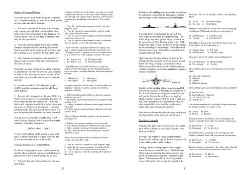
Stability in the rolling plane is usually established<br />
by setting the wings into the fuselage at a slight<br />
upward angle to the horizontal called dihedral.<br />
If a wing drops in turbulence the aircraft will<br />
‘slip’ sideways towards the dropped wing. The<br />
lower wing now has a greater angle of attack to<br />
the oncoming airflow than the upper wing. Additionally<br />
the upper wing’s airflow is being affected<br />
by the shielding of the fuselage. This differential<br />
between each wing’s lift rolls the aircraft back to<br />
straight and level flight.<br />
High wing aircraft have natural stability in the<br />
rolling plane because the centre of gravity is well<br />
below the wing creating a ‘pendulum’ effect.<br />
Where too much stability would hinder manoeuvrability<br />
designers incorporate anhedral to reduce<br />
excessive stability.<br />
anhedral<br />
Stability in the yawing plane (sometimes called<br />
directional stability) is provided by the aircraft’s<br />
fin. A air disturbance causing the aircraft to yaw<br />
will put the fin into the airflow at an angle of<br />
attack creating ‘sideways lift’ to push it back into<br />
line. Most aircraft have a large fin placed as far<br />
back as possible to increase the weathercock<br />
effect and ensure directional stability.<br />
Note that we always describe pitching, rolling and<br />
yawing relative to the pilot, not the horizon.<br />
The Pilot’s Controls<br />
Pitching: The pilot uses elevators, two moveable<br />
parts of the tailplane, to make the aircraft’s nose<br />
pitch up or down.<br />
Yawing: The rudder, a single control surface<br />
hinged to the trailing edge of the fin, is connected<br />
to the rudder pedals in the cockpit.<br />
Rolling: On the trailing edge of each wing towards<br />
the tip are moveable parts called ailerons.<br />
These move in opposite directions, one up, one<br />
down, in response to the pilot’s control column<br />
inputs. This increases lift on one wing and decreases<br />
lift on the other so that the aircraft rolls.<br />
9<br />
What part of an aircraft provides stability in the pitching<br />
plane?<br />
a) The fin. b) The undercarriage.<br />
c) The nose. d) The tailplane.<br />
In the two silhouettes on the left, these aircraft are flying<br />
towards you. What angles are the arrows pointing to?<br />
a) Dihedral angle. b) Anhedral angle.<br />
c) Lift angle. d) Cohedral angle.<br />
In the Harrier diagram, the aircraft is flying towards you.<br />
What angle is the arrow pointing to?<br />
a) Cohedral angle. b) Lift angle.<br />
c) Dihedral angle. d) Anhedral angle.<br />
What gives an aircraft stability in the rolling plane?<br />
a) Anhedral angle. b) Dihedral angle.<br />
c) The tailplane. d) The fin.<br />
Which of these gives an aircraft stability in the yawing<br />
plane?<br />
a) High centre of gravity.<br />
b) Anhedral.<br />
c) Dihedral.<br />
d) Sufficient fin area.<br />
Which of these gives an aircraft high directional stability?<br />
a) Small fin area.<br />
b) Rearward centre of gravity.<br />
c) Low centre of gravity.<br />
d) Large fin area.<br />
<strong>Air</strong>craft movements such as pitching, rolling and yawing<br />
are always described in relation to the:<br />
a) Ground. b) Pilot.<br />
c) <strong>Air</strong>flow. d) Horizon.<br />
In order to control an aircraft in the pitching plane, the<br />
pilot of an aircraft fitted with conventional controls uses:<br />
a) The ailerons. b) The fin.<br />
c) The rudder. d) The elevators.<br />
In order to control an aircraft in the yawing plane, the<br />
pilot of an aircraft fitted with conventional controls uses:<br />
a) The ailerons. b) The flaps.<br />
c) The rudder. d) The elevators.<br />
In order to control an aircraft in the rolling plane, the pilot<br />
of an aircraft fitted with conventional controls uses:<br />
a) The ailerons. b) The fin.<br />
c) The rudder. d) The elevators.