140-180-240-280 Bulletin.indd - MTH Pumps
140-180-240-280 Bulletin.indd - MTH Pumps
140-180-240-280 Bulletin.indd - MTH Pumps

Create successful ePaper yourself
Turn your PDF publications into a flip-book with our unique Google optimized e-Paper software.
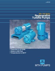
<strong>Bulletin</strong> <strong>140</strong><br />
October 2008<br />
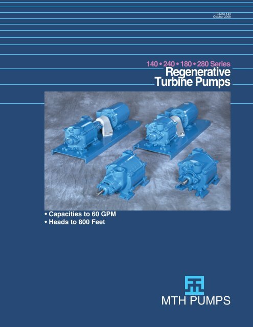
<strong>140</strong> • <strong>240</strong> • <strong>180</strong> • <strong>280</strong> Series<br />
Regenerative<br />
Turbine <strong>Pumps</strong><br />
• Capacities to 60 GPM<br />
• Heads to 800 Feet<br />
<strong>MTH</strong> PUMPS
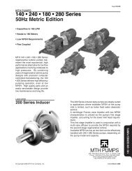
<strong>140</strong> • <strong>240</strong> • <strong>180</strong> • <strong>280</strong> Series regenerative<br />
turbine pumps represent the<br />
most economical, high performance<br />
alternative for low fl ow (to 60 GPM)<br />
applications involving moderate to<br />
high pressures (heads to 800 feet).<br />
By combining years of regenerative<br />
turbine pump designs with precision<br />
computer controlled manufacturing,<br />
the <strong>140</strong> • <strong>240</strong> • <strong>180</strong> • <strong>280</strong> Series<br />
delivers high effi ciency pumping<br />
operation, even at low NPSH. High<br />
quality parts and an easily serviceable<br />
design provide low maintenance<br />
and long life.<br />
Water Passage Design<br />
<strong>MTH</strong> has combined seventy years of<br />
water passage design with a multistage<br />
mechanical concept to achieve<br />
maximum capacity and pressure<br />
while minimizing horsepower requirements.<br />
By optimizing the number<br />
of pumping stages with each water<br />
passageway, <strong>MTH</strong> improves both<br />
effi ciency and pressure in the <strong>140</strong> •<br />
<strong>240</strong> • <strong>180</strong> • <strong>280</strong> Series, exceeding<br />
the standards realized by previous<br />
techniques.<br />
Impeller Profile<br />
One of the most notable improvements<br />
in regenerative turbine pump<br />
technology incorporated in <strong>140</strong> • <strong>240</strong><br />
• <strong>180</strong> • <strong>280</strong> Series pumps involves<br />
the ability to determine the optimum<br />
impeller width and blade length.<br />
These factors have a signifi cant effect<br />
on the required horsepower versus<br />
pressure curve for regenerative<br />
turbine pumps. By optimizing these<br />
for each <strong>140</strong> • <strong>240</strong> • <strong>180</strong> • <strong>280</strong> Series<br />
pump, peak effi ciency is improved<br />
and “off peak” horsepower requirements<br />
are reduced as well.<br />
Impeller Blades<br />
After the most favorable impeller<br />
profi le has been determined for a<br />
particular water passageway crosssection,<br />
<strong>MTH</strong> calculates the number<br />
of blades needed to maximize the<br />
performance of that pump. Current<br />
blade design in <strong>140</strong> • <strong>240</strong> • <strong>180</strong> •<br />
<strong>280</strong> Series pumps increases both effi<br />
ciency and design pressure without<br />
the manufacturing diffi culties associated<br />
with producing contoured blade<br />
impellers.<br />
State-of-the-art computer controlled<br />
machines simplify manufacturing of<br />
the various <strong>MTH</strong> impellers utilized<br />
in the <strong>140</strong> • <strong>240</strong> • <strong>180</strong> • <strong>280</strong> Series.<br />
The result is a high performance<br />
pump providing effi ciency characteristics<br />
exceeding those of more<br />
expensive units.<br />
<strong>140</strong> • <strong>240</strong> • <strong>180</strong> • <strong>280</strong> Series<br />
Regenerative<br />
Turbine <strong>Pumps</strong><br />
NPSH Requirements<br />
<strong>140</strong> • <strong>240</strong> • <strong>180</strong> • <strong>280</strong> Series regenerative<br />
turbine pumps meet low<br />
net positive suction head (NPSH)<br />
requirements without effi ciency loss.<br />
This is achieved by keeping the inlet<br />
fl uid velocity low and then gently accelerating<br />
to passageway velocities.<br />
Low NPSH Requirements<br />
<strong>240</strong> • <strong>280</strong> Series regenerative turbine<br />
pumps provide exceptionally low<br />
NPSH requirements to suit boiler<br />
feed water deaerator applications.<br />
This reduced NPSH is obtained by<br />
using a fi rst stage centrifugal Francis<br />
vane impeller with inlet fl ow paths<br />
shaped to maintain a constant fl uid<br />
velocity. This reduces entry losses<br />
to the impeller as well as maintaining<br />
pump effi ciency. A multi-vane diffuser<br />
is used in conjunction with the<br />
centrifugal impeller for balancing radial<br />
loads and extracting the maximum<br />
pressure from the fl ow produced by<br />
the fi rst stage impeller. Pressure<br />
and fl ow produced by the low NPSH<br />
inducer assures that the succeeding<br />
stages are adequately fed.<br />
STANDARD MATERIALS<br />
PART<br />
BRONZE<br />
BRONZE ALL<br />
STAINLESS<br />
ALL IRON<br />
FITTED<br />
RING<br />
BRONZE STEEL<br />
Cover<br />
Cast Iron Cast Iron Cast Iron Bronze Stainless Steel<br />
ASTM A48 ASTM A48 ASTM A48 ASTM B62 AISI 316<br />
Seal Cup<br />
Cast Iron Cast Iron Cast Iron Bronze Stainless Steel<br />
ASTM A48 ASTM A48 ASTM A48 ASTM B62 AISI 316<br />
Bearing Arm<br />
Cast Iron Cast Iron Cast Iron Bronze Stainless Steel<br />
ASTM A48 ASTM A48 ASTM A48 ASTM B62 AISI 316<br />
Channel Ring<br />
Cast Iron Cast Iron Bronze Bronze Stainless Steel<br />
ASTM A48 ASTM A48 ASTM B62 ASTM B62 AISI 316<br />
Impeller<br />
Bronze Carbon Steel Bronze Bronze W88<br />
ASTM B62 12L14 ASTM B62 ASTM B62 ASTM A494<br />
Shaft<br />
Stainless Steel Stainless Steel Stainless Steel Stainless Steel Stainless Steel<br />
AISI 416 AISI 416 AISI 416 AISI 316 AISI 316<br />
“O” Rings Buna N Buna N Buna N Buna N Viton A<br />
Seals EPR/Carbon EPR/Carbon EPR/Carbon Buna/Ceramic Viton/Ceramic<br />
Seats EPR/Ceramic EPR/Ni-Resist EPR/Ni-Resist Buna/Ceramic Viton/Ceramic<br />
Ball Bearing #204 #204 #204 #204 #204<br />
LIMITATIONS<br />
Discharge Pressure<br />
Seal Pressure*<br />
Suction Pressure (Min)<br />
Speed<br />
Horsepower<br />
400 PSI<br />
200 PSI<br />
26” Hg. Vac.<br />
1750 RPM<br />
15 HP<br />
Temperature<br />
Standard Construction<br />
-20° F<br />
Ceramic Seal Seat - Water +230° F<br />
Ni-Resist Seal Seat - Water +230° F<br />
Silicon Carbide Seal Seat<br />
+250° F<br />
& External Seal Flush<br />
* Suction Pressure Plus a Percentage of Differential<br />
Pressure
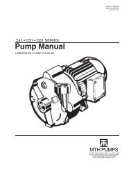
<strong>140</strong> • <strong>240</strong> • <strong>180</strong> • <strong>280</strong> SERIES<br />
Design Features<br />
<strong>MTH</strong> <strong>140</strong> • <strong>240</strong> • <strong>180</strong> • <strong>280</strong> Series<br />
regenerative turbine pumps are<br />
engineered to provide long life, lowmaintenance<br />
service for low-fl ow<br />
applications involving moderate to<br />
high pressures -- such as boiler feed<br />
and similar uses. Available in single,<br />
two, three, or four stage models,<br />
<strong>MTH</strong> pumps offer these proven<br />
design features...<br />
Steep Operating Characteristics.<br />
Near-constant capacity is maintained<br />
over wide variations in pressure.<br />
High shut-off pressure overcomes<br />
temporary line resistance.<br />
No Vapor Binding. <strong>MTH</strong> impellers<br />
are designed to handle up to 20%<br />
vapor by volume in the liquid being<br />
pumped.<br />
No Metal to Metal Contact. <strong>MTH</strong><br />
clearances enable handling of nonlubricating<br />
fl uids while maintaining<br />
adequate heads.<br />
Low Head Requirements. <strong>MTH</strong><br />
pumps have excellent NPSH<br />
characteristics, which makes them<br />
ideally suited for diffi cult applications.<br />
Minimum Shaft Deflection provided<br />
by heavy-duty outboard bearing<br />
supports on both sides of the<br />
impeller.<br />
100% Tested.<br />
Every pump is fully tested to verify<br />
performance prior to shipment.<br />
Mechanical Seals incorporate<br />
EPR or Viton seals, ceramic or<br />
Ni-resist faces, and stainless steel<br />
components. These advanced<br />
seals permit elevated-temperature<br />
operation even with aggressive fl uids.<br />
Lip-Sealed #204 Ball Bearings<br />
on both inboard and outboard<br />
ends, operate within rugged cast-<br />
Optional Features<br />
Construction Materials. Bronze<br />
fi tted, all iron, bronze ring, all bronze<br />
and 316 stainless steel are available<br />
as stock materials.<br />
Mechanical Seals. Buna,<br />
EPR, Viton, Neoprene or Tefl on<br />
elastomers, Ni-resist, Tungsten, or<br />
Silicone Carbide seats and balanced<br />
or double seal arrangements are all<br />
available.<br />
Hydraulically balanced impellers<br />
iron bearing supports and are<br />
permanently lubricated for long,<br />
maintenance-free life.<br />
Replaceable Channel Rings, along<br />
with “O”rings at all sealing points,<br />
contribute to trouble-free operation.<br />
Non-Cavitating.<br />
<strong>140</strong>•<strong>240</strong>•<strong>180</strong>•<strong>280</strong> Series pumps may<br />
be operated under adverse inlet conditions<br />
without audible or measurable<br />
cavitation.<br />
”O”Ring Gaskets. Buna, EPR,<br />
Viton, Neoprene or Tefl on are all<br />
available.<br />
Seal Flush Line. External fl ush line<br />
from pump discharge to seal faces allow<br />
for higher fl uid temperature.<br />
External Water Seal Connection.<br />
Tapped openings can be provided for<br />
seal fl ushing from an external source.<br />
Replaceable<br />
channel rings<br />
Balanced Radial Loads. On<br />
multi-stage <strong>MTH</strong> pumps, radial<br />
load equalization is designed into<br />
the pump, eliminating the need for<br />
external adjustment<br />
Standard <strong>Pumps</strong> have hydraulically<br />
balanced impellers, 3/4” stainless<br />
steel shafts, and corrosion-resistant<br />
seals throughout.<br />
400# Case Working Pressure.<br />
Rigid structure is designed for maximum<br />
casing strength.<br />
Large stainless<br />
shaft for minimum<br />
defl ection<br />
Lip sealed<br />
ball bearings<br />
O-ring gaskets<br />
prevent leakage<br />
Advanced design<br />
mechanical seals<br />
Water fl inger<br />
to protect ball<br />
bearings<br />
200 Series Inducer<br />
for Low NPSH<br />
The 200 Series inducer style pumps<br />
are ideally suited to applications where<br />
available NPSH at the pump inlet is<br />
limited, such as boiler feed water<br />
deaerator service.<br />
A centrifugal impeller with low NPSH<br />
characteristics is utilized as the pump’s<br />
first stage impeller, providing for the<br />
lower inlet head requirement.<br />
This first stage impeller is used in<br />
conjunction with a multi-vane diffuser<br />
to provide the NPSH required by the<br />
second stage regenerative turbine.<br />
Available NPSH as low as one foot can<br />
be effectively handled with <strong>240</strong> • <strong>280</strong><br />
Series pumps, depending on the pump<br />
model and capacity.
<strong>MTH</strong> PUMPS<br />
Regenerative Turbine Education<br />
The primary difference between<br />
a centrifugal and a regenerative<br />
turbine pump is that fl uid only travels<br />
through a centrifugal impeller once,<br />
while in a turbine, it takes many<br />
trips through the vanes. Referring<br />
to the crosssection<br />
diagram,<br />
the impeller<br />
vanes move<br />
within the fl owthrough<br />
area of<br />
the water channel<br />
passageway.<br />
Once the liquid<br />
enters the pump,<br />
it is directed into the vanes which<br />
push the fl uid forward and impart<br />
a centrifugal force outward to the<br />
impeller periphery. An orderly<br />
circulatory fl ow is therefore imposed<br />
by the impeller vane which is<br />
converted to velocity. Fluid velocity<br />
(or kinetic energy) is then available<br />
for conversion to fl ow and pressure<br />
depending on the external system’s<br />
fl ow resistance as diagrammed by a<br />
system curve.<br />
It is useful to note at this point, that<br />
in order to prevent the internal loss<br />
of the pressure building capability of<br />
an <strong>MTH</strong> regenerative turbine, close<br />
internal clearances are required.<br />
In many cases, depending on the<br />
size of the pump, impeller to casing<br />
clearances may be as little as onethousandth<br />
of an inch on each side.<br />
Therefore, these pumps are suitable<br />
for use only on applications with<br />
clean fl uids and systems, or else<br />
the fl uid must be pre-fi ltered before<br />
reaching the pump.<br />
Next, as the circulatory fl ow is<br />
imposed on the fl uid and it reaches<br />
the fl uid channel periphery, it is then<br />
redirected by the<br />
specially shaped<br />
fl uid channels,<br />
around the<br />
side of<br />
the impeller, and back into the I.D.<br />
of the turbine impeller vanes, where<br />
the process begins again. This<br />
cycle occurs many times as the fl uid<br />
passes through the pump. Each trip<br />
through the vanes generates more<br />
fl uid velocity, which can then be<br />
converted into more pressure. The<br />
multiple cycles through the turbine<br />
vanes are called regeneration, hence<br />
the name regenerative turbine.<br />
The overall result of this process<br />
is a pump with pressure building<br />
capability ten or more times that of<br />
a centrifugal pump with the same<br />
impeller diameter and speed.<br />
In some competitive designs, you will<br />
fi nd that only a single-sided impeller<br />
is used. That design suffers from<br />
a thrust load in the direction of the<br />
motor that must be carried by the<br />
motor bearings. <strong>MTH</strong> turbines use a<br />
two-sided impeller design that builds<br />
pressure equally on both sides.<br />
This has the advantage of allowing<br />
the pump pressure to hydraulically<br />
self-center the impeller in the close<br />
clearance impeller cavity, while not<br />
burdening the motor bearings with<br />
excessive thrust loads.<br />
<strong>140</strong> • <strong>240</strong> • <strong>180</strong> • <strong>280</strong> SERIES<br />
Engineering Specifications<br />
<strong>140</strong> • <strong>180</strong> Series<br />
The contractor shall furnish (and install as shown<br />
on the plans) an <strong>MTH</strong> Turboflex regenerative type<br />
pump model_________ size______ of (BRONZE<br />
FITTED) (BRONZE RING) (ALL IRON) (ALL<br />
BRONZE) (316 STAINLESS STEEL) construction.<br />
Each pump shall have a capacity of ____GPM<br />
when operating at a total head of _______feet<br />
at the specifi ed temperature, viscosity, specifi c<br />
gravity, and with _______feet NPSHA. The<br />
maximum speed shall not exceed 1750 RPM.<br />
Pump shall be of the vertically split case design<br />
with removable bearing housings and is to be<br />
furnished with mechanical seals. The channel<br />
rings shall be replaceable external type. The<br />
suction connection shall be _____” NPT located<br />
in the top vertical position and be cast separately<br />
from the discharge. The discharge shall be ____<br />
__” NPT in the top vertical position and the pump<br />
shall be self-venting. The impeller(s) shall be<br />
located on a stainless steel shaft between sealed<br />
grease lubricated ball bearings. The impeller(s)<br />
shall be hydraulically self positioning with no<br />
external adjustment necessary. Each pump shall<br />
be tested at the specifi ed capacity and head prior<br />
to shipment. The pump shall be mounted on a<br />
steel baseplate, fl exibly coupled with aluminum<br />
guard to a ___HP ____phase _____Hertz<br />
______volt _____RPM horizontal (DRIP-PROOF)<br />
(TOTALLY ENCLOSED) (EXPLOSION PROOF)<br />
motor. The motor is to be sized to prevent<br />
overloading at the highest head condition listed<br />
in the specifi cation.<br />
<strong>240</strong> • <strong>280</strong> Series<br />
The contractor shall furnish (and install as shown<br />
on the plans) an <strong>MTH</strong> Turboflex low NPSH<br />
inducer style regenerative type pump model_<br />
________ size______ of (BRONZE FITTED)<br />
(BRONZE RING) (ALL IRON) (ALL BRONZE)<br />
(316 STAINLESS STEEL) construction. Each<br />
pump shall have a capacity of ____GPM when<br />
operating at a total head of _______feet at the<br />
specifi ed temperature, viscosity, specifi c gravity,<br />
and with _______feet NPSHA. The maximum<br />
speed shall not exceed 1750 RPM. Pump shall be<br />
low NPSHR inducer style design with a centrifugal<br />
Francis vane design impeller and a multi-vane<br />
diffuser for balancing radial loads. Pump shall be<br />
of the vertically split case design with removable<br />
bearing housings and is to be furnished with<br />
mechanical seals. The channel rings shall<br />
be replaceable external type. The suction<br />
connection shall be _____” NPT located in the<br />
top vertical position and be cast separately from<br />
the discharge. The discharge shall be ______”<br />
NPT in the top vertical position and the pump shall<br />
be self-venting. The impeller(s) shall be located<br />
on a stainless steel shaft between sealed grease<br />
lubricated ball bearings. The impeller(s) shall<br />
be hydraulically self positioning with no external<br />
adjustment necessary. Each pump shall be<br />
tested at the specifi ed capacity and head prior to<br />
shipment. The pump shall be mounted on a steel<br />
baseplate, fl exibly coupled with aluminum guard<br />
to a ___HP ___phase _____Hertz ______volt<br />
_____RPM horizontal (DRIP-PROOF) (TOTALLY<br />
ENCLOSED) (EXPLOSION PROOF) motor. The<br />
motor is to be sized to prevent overloading at the<br />
highest head condition listed in the specifi cation.
<strong>140</strong> • <strong>240</strong> • <strong>180</strong> • <strong>280</strong> SERIES<br />
Cold Water Selection Guide<br />
U.S. GALLONS PER MINUTE<br />
HEAD 4 5 6 8 10 12 15 20 25 30 40 50<br />
IN<br />
FEET<br />
Model<br />
HP<br />
Model<br />
HP<br />
Model<br />
HP<br />
Model<br />
HP<br />
Model<br />
HP<br />
Model<br />
HP<br />
Model<br />
HP<br />
Model<br />
HP<br />
Model<br />
HP<br />
Model<br />
HP<br />
Model<br />
HP<br />
Model<br />
HP<br />
25 * * *<br />
141D<br />
.5<br />
141E<br />
.5<br />
141F<br />
.5<br />
141G<br />
.5<br />
141H<br />
.75<br />
141I<br />
.75<br />
141IA<br />
1<br />
181M<br />
1.5<br />
181P<br />
1.5<br />
50 * *<br />
141D<br />
.5<br />
141E<br />
.5<br />
141F<br />
.5<br />
141G<br />
.5<br />
141H<br />
.75<br />
141I<br />
1<br />
181K<br />
1<br />
181M<br />
1.5<br />
181P<br />
1.5<br />
181R<br />
2<br />
75 * *<br />
141D<br />
.5<br />
141E<br />
.5<br />
141F<br />
.75<br />
142F<br />
.75<br />
141H<br />
1<br />
141I<br />
1<br />
141IA<br />
1.5<br />
181M<br />
2<br />
181R<br />
3<br />
182R<br />
5<br />
100 *<br />
141D<br />
.5<br />
141E<br />
.5<br />
141F<br />
.75<br />
142F<br />
.75<br />
141H<br />
1<br />
141I<br />
1<br />
141IA<br />
1.5<br />
182K<br />
2<br />
181P<br />
2<br />
182P<br />
3<br />
183R<br />
5<br />
125<br />
141D<br />
.75<br />
141E<br />
.75<br />
141E<br />
.75<br />
141G<br />
1<br />
142F<br />
1<br />
142G<br />
1.5<br />
142H<br />
1.5<br />
142I<br />
2<br />
182K<br />
2<br />
182M<br />
3<br />
182P<br />
3<br />
183R<br />
5<br />
150<br />
141E<br />
.75<br />
141E<br />
.75<br />
142D<br />
1<br />
143E<br />
1<br />
142G<br />
1.5<br />
143G<br />
1.5<br />
142H<br />
2<br />
143I<br />
3<br />
142IA<br />
3<br />
182M<br />
5<br />
182R<br />
5<br />
184R<br />
7.5<br />
175<br />
141E<br />
1<br />
142D<br />
1<br />
142E<br />
1<br />
142F<br />
1.5<br />
142G<br />
1.5<br />
142H<br />
2<br />
142I<br />
2<br />
182K<br />
3<br />
143IA<br />
3<br />
182P<br />
5<br />
183P<br />
5<br />
200<br />
141E<br />
1<br />
142D<br />
1<br />
142E<br />
1<br />
142F<br />
1.5<br />
143F<br />
1.5<br />
142H<br />
2<br />
142I<br />
3<br />
142IA<br />
3<br />
183K<br />
3<br />
183M<br />
5<br />
183R<br />
7.5<br />
225<br />
142D<br />
1.5<br />
143D<br />
1.5<br />
142E<br />
1.5<br />
142F<br />
1.5<br />
143G<br />
2<br />
143H<br />
3<br />
142I<br />
3<br />
142IA<br />
3<br />
143IA<br />
5<br />
183P<br />
5<br />
184P<br />
7.5<br />
250<br />
142D<br />
1.5<br />
143D<br />
1.5<br />
142E<br />
1.5<br />
143F<br />
2<br />
143G<br />
2<br />
143H<br />
3<br />
143I<br />
3<br />
143IA<br />
5<br />
144IA<br />
5<br />
183P<br />
5<br />
184R<br />
10<br />
300<br />
143D<br />
1.5<br />
142E<br />
1.5<br />
143E<br />
1.5<br />
143F<br />
2<br />
143H<br />
3<br />
142I<br />
3<br />
143I<br />
5<br />
143IA<br />
5<br />
183P<br />
7.5<br />
184P<br />
7.5<br />
350<br />
144D<br />
2<br />
144D<br />
2<br />
143E<br />
2<br />
144F<br />
3<br />
144H<br />
5<br />
144H<br />
5<br />
143I<br />
5<br />
144IA<br />
5<br />
184M<br />
7.5<br />
184P<br />
7.5<br />
400<br />
144D<br />
2<br />
143E<br />
2<br />
144E<br />
2<br />
144G<br />
3<br />
144H<br />
5<br />
143I<br />
5<br />
144I<br />
5<br />
144IA<br />
5<br />
184P<br />
7.5<br />
450<br />
144D<br />
2<br />
143E<br />
2<br />
144E<br />
2<br />
144G<br />
3<br />
143I<br />
5<br />
144I<br />
5<br />
183K<br />
7.5<br />
184P<br />
10<br />
184R<br />
15<br />
500<br />
144D 144E 144F 143I 143I 144I 144IA<br />
3 3 3 7.5 7.5 7.5 7.5 Selections based on coldwater<br />
550<br />
143E 144E 143I 143I 144I 144IA<br />
flooded suction 1.0 S.G. Open<br />
3 3 5 5 7.5 7.5<br />
Dripproof Motor.<br />
Consult individual pump curve for<br />
600<br />
144E 144G 143I 144I 144I 144IA<br />
3 5 7.5 7.5 7.5 7.5<br />
final selection.<br />
*Refer to T41 Series <strong>Bulletin</strong>.<br />
650<br />
144E<br />
3<br />
700<br />
144E<br />
3<br />
Boiler Feed Selection Guide<br />
Evap<br />
Rate<br />
GPM<br />
BOILER PRESSURE IN PSI<br />
15 50 100 125 150 200 250<br />
Model HP Model HP Model HP Model HP Model HP Model HP Model HP<br />
Boiler<br />
HP<br />
Pump<br />
GPM<br />
15 1.0 3.1 141D .3 141D .75 142E 1.0 142E 1.5 142F 1.5 143E 2.0 144E 3.0<br />
20 1.4 4.1 141D .3 141D .75 142E 1.0 142E 1.5 142F 1.5 143E 2.0 144E 3.0<br />
25 1.7 4.4 141D .3 141D .75 142E 1.0 142E 1.5 143E 1.5 143E 2.0 144E 3.0<br />
30 2.1 5.0 141D .3 141D .75 142E 1.0 142E 1.5 143E 1.5 143E 2.0 144E 3.0<br />
40 2.8 5.6 141D .3 141E .75 142F 1.5 142G 2.0 143E 1.5 144F 3.0 144I 7.5<br />
50 3.5 7.0 141D .3 141F .75 142F 1.5 143F 2.0 143F 2.0 144I 5.0 144I 7.5<br />
60 4.2 8.3 141E .3 141F .75 142G 2.0 143G 2.0 143G 5.0 144I 5.0 144I 7.5<br />
70 4.8 9.6 141F .5 141I 1.5 142I 3.0 143I 3.0 143I 5.0 144I 5.0 144I 7.5<br />
80 5.5 11.0 141F .5 141I 1.5 142I 3.0 143I 3.0 143I 5.0 144I 5.0 144I 7.5<br />
100 6.9 14.0 141G .5 141I 1.5 142IA 3.0 143I 3.0 143IA 5.0 144I 5.0 152I 10.0<br />
125 8.6 17.5 141I .75 141IA 1.5 142IA 3.0 143I 3.0 143IA 5.0 144IA 7.5 152I 10.0<br />
150 10.7 21.0 141I .75 141IA 1.5 151I 5.0 143IA 5.0 144IA 5.0 152I 7.5 153I 10.0<br />
200 13.8 28.0 141IA 1.0 182K 2.0 151K 5.0 152I 5.0 162D 7.5 162D 10.0 163D 15.0<br />
250 17.3 33.0 181M 1.5 151K 3.0 152K 5.0 152K 7.5 162D 7.5 162G 10.0 153L 15.0<br />
300 20.7 38.0 181M 1.5 151K 3.0 152K 5.0 152K 7.5 152L 10.0 162G 15.0 153L 15.0<br />
350 24.2 43.0 181P 1.5 151L 5.0 152L 7.5 152L 10.0 152L 10.0 162G 15. 153L 15.0<br />
400 27.6 48.0 181R 2.0 151L 5.0 162L 7.5 152L 10.0 162G 15.0 162G 15.0 163G 20.0<br />
500 34.5 57.0 151L 3.0 161G 5.0 162G 10.0 162G 10.0 163G 15.0 164G 20.0 173H 25.0<br />
600 41.5 71.0 161G 3.0 161G 5.0 172H 15.0 172H 15.0 172J 20.0 173H 20.0 173K 30.0<br />
700 43.5 77.0 161G 3.0 171K 7.5 172K 15.0 172K 15.0 173K 20.0 174H 20.0 174J 30.0<br />
NOTES<br />
Selections are for water at 200°F (Maximum) with above 3 feet NPSHA (Net Positive Suction Head Available) over NPSHR (Net Positive Suction Head Required).<br />
All pumps are selected for intermittent (on-off) operation and with ODP (Open Drip Proof) motors operating at 1750RPM.<br />
This selection is for reference only. Refer to the technical data of the specific model number to ascertain the suitability of the model in your application, or call the factory.<br />
150 • 160 • 170 Model pump information is available in our <strong>Bulletin</strong> 150.
<strong>140</strong> • <strong>180</strong> SERIES<br />
Dimensions<br />
3/4 DIA.<br />
G<br />
INLET<br />
S<br />
DISCHARGE<br />
1/2 1/2<br />
2 15/16 T<br />
E<br />
Pump Only Dimensions<br />
PUMP SERIES INLET DISCHARGE E G S T<br />
141 1 1/4” NPT 1 1/4” NPT 2 1/8 3 13/16 4 1/4 6<br />
142 1 1/4” NPT 1 1/4” NPT 2 1/8 3 13/16 6 1/4 8<br />
143 1 1/4” NPT 1 1/4” NPT 2 1/8 3 13/16 8 1/4 10<br />
144 1 1/4” NPT 1 1/4” NPT 2 1/8 3 13/16 10 1/4 12<br />
181 1 1/2” NPT 1 1/2” NPT 2 1/4 3 11/16 5 1/2 7<br />
182 1 1/2” NPT 1 1/2” NPT 2 1/4 3 11/16 8 1/2 10<br />
183 1 1/2” NPT 1 1/2” NPT 2 1/4 3 11/16 11 1/2 13<br />
184 1 1/2” NPT 1 1/2” NPT 2 1/4 3 11/16 14 1/2 16<br />
ROTATION: Clockwise when viewed from driver end.<br />
1 1/2<br />
1 1/2<br />
C<br />
L<br />
K<br />
G<br />
S<br />
2 7/8<br />
3 1/2<br />
HD<br />
D<br />
1 1/2<br />
5 1/2<br />
7 1/4<br />
12<br />
1 TYP.<br />
4 - 17/32 Ø Foundation Holes<br />
<strong>140</strong> Series Flex Coupled Pump Dimensions<br />
ALL <strong>140</strong> MODELS MODEL 141 MODEL 142 MODEL 143 MODEL 144<br />
FRAME CPLG K D HD C S L S L S L S L<br />
56 3J 3/8 3 1/2 8 1/2 12 4 1/4 24 6 1/4 26 8 1/4 28 10 1/4 30<br />
143T 4J 5/8 3 1/2 8 1/2 13 4 1/4 24 6 1/4 26 8 1/4 28 10 1/4 30<br />
145T 4J 5/8 3 1/2 8 1/2 14 4 1/4 24 6 1/4 26 8 1/4 28 10 1/4 30<br />
182T 5J 3/4 4 1/2 9 1/2 16 4 1/4 26 6 1/4 30 8 1/4 32 10 1/4 35<br />
184T 5J 3/4 4 1/2 9 1/2 17 --- --- 6 1/4 30 8 1/4 32 10 1/4 35<br />
213T 6J 7/8 5 1/4 10 1/4 19 --- --- --- --- 8 1/4 35 10 1/4 40<br />
215T 6J 7/8 5 1/4 10 1/4 20 --- --- --- --- --- --- 10 1/4 40<br />
<strong>180</strong> Series Flex Coupled Pump Dimensions<br />
ALL <strong>180</strong> MODELS MODEL 181 MODEL 182 MODEL 183 MODEL 184<br />
FRAME CPLG K D HD C S L S L S L S L<br />
56 3J 3/8 3 1/2 8 1/2 12 5 1/2 26 8 1/2 28 11 1/2 30 14 1/2 35<br />
143T 4J 5/8 3 1/2 8 1/2 13 5 1/2 26 8 1/2 28 11 1/2 30 14 1/2 35<br />
145T 4J 5/8 3 1/2 8 1/2 14 5 1/2 26 8 1/2 28 11 1/2 30 14 1/2 35<br />
182T 5J 3/4 4 1/2 9 1/2 16 5 1/2 28 8 1/2 30 11 1/2 32 14 1/2 40<br />
184T 5J 3/4 4 1/2 9 1/2 17 5 1/2 28 8 1/2 30 11 1/2 32 14 1/2 40<br />
213T 6J 7/8 5 1/4 10 1/4 19 --- --- 8 1/2 35 11 1/2 40 14 1/2 45<br />
215T 6J 7/8 5 1/4 10 1/4 20 --- --- 8 1/2 35 11 1/2 40 14 1/2 45<br />
NOTES<br />
All dimensions in inches. May vary ± ¼ inches.<br />
Not for construction purposes unless certifi ed.<br />
ROTATION: Clockwise when viewed from driver end.
<strong>240</strong> • <strong>280</strong> SERIES<br />
Dimensions<br />
3/4 DIA.<br />
5 3/4<br />
INLET<br />
S<br />
DISCHARGE<br />
1/2 1/2<br />
6 1/4 T<br />
E<br />
Pump Only Dimensions<br />
PUMP SERIES INLET DISCHARGE E S T<br />
241 1 1/2” NPT 1 1/4” NPT 2 1/8 5 5/8 6<br />
242 1 1/2” NPT 1 1/4” NPT 2 1/8 7 5/8 8<br />
243 1 1/2” NPT 1 1/4” NPT 2 1/8 9 5/8 10<br />
244 1 1/2” NPT 1 1/4” NPT 2 1/8 11 5/8 12<br />
281 1 1/2” NPT 1 1/2” NPT 2 1/4 6 5/8 7<br />
282 1 1/2” NPT 1 1/2” NPT 2 1/4 9 5/8 10<br />
283 1 1/2” NPT 1 1/2” NPT 2 1/4 12 5/8 13<br />
284 1 1/2” NPT 1 1/2” NPT 2 1/4 15 5/8 16<br />
ROTATION: Clockwise when viewed from driver end.<br />
1 1/2<br />
1 1/2<br />
C<br />
L<br />
K<br />
5 3/4<br />
S<br />
2 7/8<br />
3 1/2<br />
HD<br />
D<br />
1 1/2<br />
5 1/2<br />
7 1/4<br />
12<br />
1 TYP.<br />
4 - 17/32 Ø Foundation Holes<br />
<strong>240</strong> Series Flex Coupled Pump Dimensions<br />
ALL <strong>240</strong> MODELS MODEL 241 MODEL 242 MODEL 243 MODEL 244<br />
FRAME CPLG K D HD C S L S L S L S L<br />
56 3J 3/8 3 1/2 8 1/2 12 5 5/8 28 7 5/8 30 9 5/8 32 11 5/8 35<br />
143T 4J 5/8 3 1/2 8 1/2 13 5 5/8 28 7 5/8 30 9 5/8 32 11 5/8 35<br />
145T 4J 5/8 3 1/2 8 1/2 14 5 5/8 28 7 5/8 30 9 5/8 32 11 5/8 35<br />
182T 5J 3/4 4 1/2 9 1/2 16 5 5/8 30 7 5/8 32 9 5/8 35 11 5/8 38<br />
184T 5J 3/4 4 1/2 9 1/2 17 5 5/8 30 7 5/8 32 9 5/8 35 11 5/8 38<br />
213T 6J 7/8 5 1/4 10 1/4 19 --- --- --- --- 9 5/8 40 11 5/8 40<br />
215T 6J 7/8 5 1/4 10 1/4 20 --- --- --- --- 9 5/8 40 11 5/8 40<br />
<strong>280</strong> Series Flex Coupled Pump Dimensions<br />
ALL <strong>280</strong> MODELS MODEL 281 MODEL 282 MODEL 283 MODEL 284<br />
FRAME CPLG K D HD C S L S L S L S L<br />
56 3J 3/8 3 1/2 8 1/2 12 6 5/8 28 9 5/8 32 12 5/8 35 15 5/8 38<br />
143T 4J 5/8 3 1/2 8 1/2 13 6 5/8 28 9 5/8 32 12 5/8 35 15 5/8 38<br />
145T 4J 5/8 3 1/2 8 1/2 14 6 5/8 28 9 5/8 32 12 5/8 35 15 5/8 38<br />
182T 5J 3/4 4 1/2 9 1/2 16 6 5/8 30 9 5/8 35 12 5/8 38 15 5/8 40<br />
184T 5J 3/4 4 1/2 9 1/2 17 6 5/8 30 9 5/8 35 12 5/8 38 15 5/8 40<br />
213T 6J 7/8 5 1/4 10 1/4 19 --- --- --- --- 12 5/8 40 15 5/8 42<br />
215T 6J 7/8 5 1/4 10 1/4 20 --- --- --- --- 12 5/8 40 15 5/8 42<br />
NOTES<br />
All dimensions in inches. May vary ± ¼ inches.<br />
Not for construction purposes unless certifi ed.<br />
ROTATION: Clockwise when viewed from driver end.
<strong>Bulletin</strong> <strong>140</strong><br />
October 2008<br />
© 2008 <strong>MTH</strong> TOOL COMPANY<br />
<strong>MTH</strong> PUMPS<br />
401 West Main Street • Plano, IL 60545-1436<br />
Phone: 630-552-4115 • Fax: 630-552-3688<br />
Email: Sales@<strong>MTH</strong><strong>Pumps</strong>.com<br />
Http://WWW.<strong>MTH</strong><strong>Pumps</strong>.com