Tooling Introduction to Crimp Technology
Tooling Introduction to Crimp Technology
Tooling Introduction to Crimp Technology

Create successful ePaper yourself
Turn your PDF publications into a flip-book with our unique Google optimized e-Paper software.
<strong>Tooling</strong> <strong>Introduction</strong> <strong>to</strong> <strong>Crimp</strong> <strong>Technology</strong><br />
Developed <strong>to</strong> replace the need <strong>to</strong> solder terminations, crimping technology provides a<br />
high quality connection between a terminal and a wire at a relatively low applied cost.<br />
The methods for applying crimp terminations depend on the application and volume,<br />
and range from hand-held devices <strong>to</strong> fully-au<strong>to</strong>mated systems. The application<br />
methods include a basic hand <strong>to</strong>ol, a press and die set, a stripper crimper or a fully<br />
au<strong>to</strong>matic wire processing system. But no matter what method is used, the setup of<br />
each <strong>to</strong>ol is critical for achieving a quality crimp.<br />
Website: Please visit the Molex website <strong>to</strong><br />
view the most current Application <strong>Tooling</strong><br />
information. The Molex website is continuously<br />
updated with the latest information.<br />
(www.molex.com)<br />
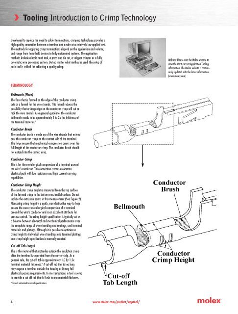
TERMINOLOGY<br />
Bellmouth (Flare)<br />
The flare that is formed on the edge of the conduc<strong>to</strong>r crimp<br />
acts as a funnel for the wire strands. This funnel reduces the<br />
possibility that a sharp edge on the conduc<strong>to</strong>r crimp will cut or<br />
nick the wire strands. As a general guideline, the conduc<strong>to</strong>r<br />
bellmouth needs <strong>to</strong> be approximately 1 <strong>to</strong> 2x the thickness of<br />
the terminal material.*<br />
Conduc<strong>to</strong>r Brush<br />
The conduc<strong>to</strong>r brush is made up of the wire strands that extend<br />
past the conduc<strong>to</strong>r crimp on the contact side of the terminal.<br />
This helps ensure that mechanical compression occurs over the<br />
full length of the conduc<strong>to</strong>r crimp. The conduc<strong>to</strong>r brush should<br />
not extend in<strong>to</strong> the contact area.<br />
Conduc<strong>to</strong>r <strong>Crimp</strong><br />
This is for the metallurgical compression of a terminal around<br />
the wire’s conduc<strong>to</strong>r. This connection creates a common<br />
electrical path with low resistance and high current carrying<br />
capabilities.<br />
Conduc<strong>to</strong>r <strong>Crimp</strong> Height<br />
The conduc<strong>to</strong>r crimp height is measured from the <strong>to</strong>p surface<br />
of the formed crimp <strong>to</strong> the bot<strong>to</strong>m most radial surface. Do not<br />
include the extrusion points in this measurement (See Figure 2).<br />
Measuring crimp height is a quick, non-destructive way <strong>to</strong> help<br />
ensure the correct metallurgical compression of a terminal<br />
around the wire’s conduc<strong>to</strong>r and is an excellent attribute for<br />
process control. The crimp height specification is typically set as<br />
a balance between electrical and mechanical performance over<br />
the complete range of wire stranding and coatings, and terminal<br />
materials and platings. Although it is possible <strong>to</strong> optimize a<br />
crimp height <strong>to</strong> individual wire strandings and terminal platings,<br />
one crimp height specification is normally created.<br />
Cut-off Tab Length<br />
This is the material that protrudes outside the insulation crimp<br />
after the terminal is separated from the carrier strip. As a<br />
general rule, the cut-off tab is approximately 1.0 by 1.5x<br />
terminal material thickness.* A cut-off tab that is <strong>to</strong>o long<br />
may expose a terminal outside the housing or it may fail<br />
electrical spacing requirements. In most situations, a <strong>to</strong>ol is setup<br />
<strong>to</strong> provide a cut-off tab that is flush <strong>to</strong> one material thickness.<br />
*Consult individual terminal specifications<br />
<br />
www.molex.com/product/app<strong>to</strong>ol/
<strong>Tooling</strong> <strong>Introduction</strong> <strong>to</strong> <strong>Crimp</strong> <strong>Technology</strong><br />
TERMINOLOGY (CONTINUED)<br />
Extrusions (Flash)<br />
These are the small flares that form on the bot<strong>to</strong>m of the conduc<strong>to</strong>r crimp resulting from the<br />
clearance between the punch and anvil <strong>to</strong>oling. If the anvil is worn or the terminal is over-crimped,<br />
excessive extrusion results. An uneven extrusion may also result if the punch and anvil alignment<br />
is not correct, if the feed adjustment is off, or if there is insufficient/excessive terminal drag.<br />
Insulation <strong>Crimp</strong> (Strain Relief)<br />
This is the part of the terminal that provides both wire support for insertion in<strong>to</strong> the housing and<br />
allows the terminal <strong>to</strong> withstand shock and vibration. The terminal needs <strong>to</strong> hold the wire as<br />
firmly as possible without cutting through <strong>to</strong> the conduc<strong>to</strong>r strands. The acceptability of an<br />
insulation crimp is subjective and depends on the application. A bend test is recommended <strong>to</strong><br />
determine whether or not the strain relief is acceptable for each particular application.<br />
Insulation <strong>Crimp</strong> Height<br />
Molex does not specify insulation crimp heights because of the wide variety of insulation<br />
thickness, material, and hardness. Most terminals are designed <strong>to</strong> accommodate multiple wire<br />
ranges. Within the terminals range, an insulation diameter may not completely surround the<br />
wire or fully surround the diameter of the wire. This condition will still provide an acceptable<br />
insulation crimp for most applications.<br />
n A large insulation should firmly grip at least 88% of the wire<br />
n A smaller insulation should firmly grip at least 50% of the wire and firmly hold the<br />
<strong>to</strong>p of the wire<br />
To evaluate the insulation section cut the wire flush with the back of the terminal. Once the<br />
optimum setting for the application is determined it is important <strong>to</strong> document the insulation<br />
crimp height. Then, as part of the setup procedure the opera<strong>to</strong>r can check the crimp height.<br />
Insulation Position<br />
This is the location of the insulation in relation <strong>to</strong> the transition area between the conduc<strong>to</strong>r and<br />
insulation crimps. Equal amounts of the conduc<strong>to</strong>r strands and insulation need <strong>to</strong> be visible in<br />
the transition area. The insulation position ensures that the insulation is crimped along the full<br />
length of the insulation crimp, and that no insulation gets crimped under the conduc<strong>to</strong>r crimp.<br />
The insulation position is set by the wire s<strong>to</strong>p and strip length for bench applications. For<br />
au<strong>to</strong>matic wire processing applications the insulation position is set by the in/out press adjustment.<br />
Strip Length<br />
The strip length is determined by measuring<br />
the exposed conduc<strong>to</strong>r strands after the<br />
insulation is removed. The strip length<br />
determines the conduc<strong>to</strong>r brush length when<br />
the insulation position is centered.<br />
Process<br />
The combination of people, equipment, <strong>to</strong>oling, materials, methods and procedures needed<br />
<strong>to</strong> produce a crimp termination. Process control is used <strong>to</strong> track attributes over time <strong>to</strong> aid<br />
in the detection of change <strong>to</strong> the process. Detecting a process change when it happens helps<br />
prevent many thousands of bad crimps.<br />
Pull Force Testing<br />
Pull Force Testing is a quick, destructive way <strong>to</strong> evaluate the mechanical properties of a<br />
crimp termination. When making a crimp, enough pressure must be applied <strong>to</strong> breakdown<br />
the oxides that build up on the stripped conduc<strong>to</strong>r and the tin plating on the inside of the<br />
terminal grip. This is necessary <strong>to</strong> provide a good metal-<strong>to</strong>-metal contact. If this does not<br />
occur, resistance can increase. Over crimping a crimp termination will reduce the circular<br />
area of the conduc<strong>to</strong>r and increase resistance.<br />
Pull Force Testing is also a good indica<strong>to</strong>r of problems in the process. Cut or nicked strands<br />
in the stripping operation, lack of bellmouth or conduc<strong>to</strong>r brush, or incorrect crimp height or<br />
<strong>to</strong>oling will reduce pull force. Wire properties and stranding, and terminal design (material<br />
thickness and serration design), also can increase or decrease pull force levels.<br />
www.molex.com/product/app<strong>to</strong>ol/
<strong>Tooling</strong> <strong>Introduction</strong> <strong>to</strong> <strong>Crimp</strong> <strong>Technology</strong><br />
TERMINOLOGY (CONTINUED)<br />
Shut Height<br />
The distance, at bot<strong>to</strong>m dead<br />
center on a press, from the<br />
<strong>to</strong>oling mounting base plate <strong>to</strong><br />
the <strong>to</strong>oling connection point on<br />
the ram of the press.<br />
Terminal Position<br />
The terminal position is set by the<br />
alignment of the terminal <strong>to</strong> the<br />
forming punch and anvils, and the<br />
carrier strip cut-off <strong>to</strong>oling. The<br />
<strong>to</strong>ol set-up determines conduc<strong>to</strong>r<br />
bellmouth, cut-off tab length, and<br />
terminal extrusions.<br />
*Consult individual terminal specifications<br />
ASSOCIATED MATERIALS<br />
Caliper<br />
A gauge, consisting of two<br />
opposing blades, for measuring<br />
linear dimensional attributes.<br />
Ruler (Pocket Scale)<br />
This is used <strong>to</strong> estimate the five<br />
piece measurement of bellmouth,<br />
cut-off tab, conduc<strong>to</strong>r brush, wire<br />
position, and strip length. The<br />
recommended maximum<br />
resolution is .5mm (.020 in).<br />
Eye Loop<br />
A magnification <strong>to</strong>ol, normally 10x power<br />
or greater, which is used <strong>to</strong> aid visual<br />
evaluation of a crimp termination.<br />
Pull Tester (Reference Figure 5)<br />
A device used <strong>to</strong> determine the mechanical strength of a crimp termination. Most pull testing<br />
is done with a device that clamps the wire, pulls at a set speed, and measures force by means<br />
of a load cell. A pull tester also can be as simple as hanging fixed weights on the wire for<br />
a minimum of one minute.<br />
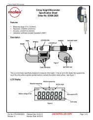
<strong>Crimp</strong> Micrometer<br />
This is a micrometer specifically designed <strong>to</strong><br />
measure crimp height. The measurement is<br />
taken in the center of the crimp so it is not<br />
influenced by the conduc<strong>to</strong>r bellmouth. It<br />
has a thin blade that supports the <strong>to</strong>p of the<br />
crimp while a pointed section determines<br />
the bot<strong>to</strong>m most radial surface.<br />
Toolmaker’s Microscope<br />
This is used for close visual<br />
evaluation and statistical<br />
measurement of bellmouth,<br />
cut-off tab, conduc<strong>to</strong>r brush,<br />
wire position, and strip length.<br />
<br />
www.molex.com/product/app<strong>to</strong>ol/
<strong>Tooling</strong> <strong>Introduction</strong> <strong>to</strong> <strong>Crimp</strong> <strong>Technology</strong><br />
IDT TOOLING INTRODUCTION<br />
Insulation Displacement <strong>Technology</strong>, IDT, is a wire termination<br />
technique in which an insulated wire is pressed in<strong>to</strong> a terminal<br />
slot smaller than the conduc<strong>to</strong>r diameter, displacing the<br />
insulation and forming an electrical contact between the<br />
terminal and conduc<strong>to</strong>r.<br />
Insulation displacement offers 3 major advantages over other<br />
termination techniques:<br />
n Electrical connec<strong>to</strong>rs are supplied <strong>to</strong> the cus<strong>to</strong>mer with the<br />
terminals loaded in<strong>to</strong> their final positions. This feature<br />
results in cus<strong>to</strong>mer labor savings as additional operations<br />
are not required <strong>to</strong> complete the assembly.<br />
n Hourly production rates are maximized through the simultaneous<br />
mass insertion of wires in<strong>to</strong> multiple connec<strong>to</strong>rs.<br />
n IDT allows for multiple connec<strong>to</strong>rs <strong>to</strong> be placed along a<br />
harness assembly (daisy chain) without the need <strong>to</strong> double<br />
terminate circuits.<br />
Molex offers a full line of IDT terminating equipment ranging<br />
from simple hand <strong>to</strong>ols <strong>to</strong> fully au<strong>to</strong>matic cable and discrete<br />
wire harness assembly machines. All <strong>to</strong>ols are designed and<br />
manufactured using the latest technologies <strong>to</strong> ensure high<br />
quality in <strong>to</strong>ol performance and in the product they produce.<br />
IDT TERMINATING EQUIPMENT<br />
Hand Tools<br />
Low volume users can choose from a range of snap-on<br />
modules that mount <strong>to</strong> a common pis<strong>to</strong>l or bench mounted<br />
holder. These modules can be easily changed <strong>to</strong> accommodate<br />
various connec<strong>to</strong>r styles. Typically, these <strong>to</strong>ols<br />
yield production rates of approximately 300 terminations<br />
per hour.<br />
Manual Press Tools<br />
For medium production volumes, Molex offers a variety<br />
of manual press bench <strong>to</strong>ols designed <strong>to</strong> process cable or<br />
discrete wire <strong>to</strong> further increase productivity. For <strong>to</strong>ols in this<br />
category, production rates of up <strong>to</strong> 250 assemblies per hour<br />
for cable or 500 terminations per hour for discrete wire are<br />
not uncommon.<br />
Semi-Au<strong>to</strong>matic Bench Tools<br />
For higher production volumes, Molex offers a variety<br />
of semi-au<strong>to</strong>matic bench <strong>to</strong>ols <strong>to</strong> increase the end users’<br />
productivity. For <strong>to</strong>ols in this category, production rates of up<br />
<strong>to</strong> 900 assemblies per hour for cable or 1200 terminations<br />
per hour for discrete wire are normally realized. In addition<br />
<strong>to</strong> inserting wires in<strong>to</strong> terminals, selected machine models are<br />
already equipped <strong>to</strong>:<br />
n Au<strong>to</strong>matically unload connec<strong>to</strong>rs from packaging such as<br />
extruded tubes, mylar film, etc.<br />
n Perform secondary operations, for example, carrier strip<br />
breakoff, terminal insertion, product marking, etc.<br />
Fully Au<strong>to</strong>matic Machines<br />
For large production requirements, Molex offers its cus<strong>to</strong>mers<br />
fully au<strong>to</strong>matic modular assembly machines. This modular<br />
concept allows machines <strong>to</strong> be designed and built <strong>to</strong> meet<br />
exact cus<strong>to</strong>mer requirements. Additionally, this concept enables<br />
cus<strong>to</strong>mers <strong>to</strong> add options at a future date as production<br />
needs change. In general, machines in this category produce<br />
10,000 terminations per hour or better. All machines are<br />
designed with fully-integrated PLC controls that include “user<br />
friendly” self-diagnostic software features <strong>to</strong> minimize set-up<br />
time and maximize machine uptime and system utilization.<br />
Special Machines<br />
Molex can quote special machines upon request with<br />
optional features that parallel the Phoenix /Eagle Series.<br />
In general, these machines differ by the manner in which<br />
connec<strong>to</strong>r termination and wire handling is accomplished.<br />
Additionally, daisy chain and different connec<strong>to</strong>r orientations<br />
can be accomplished.<br />
www.molex.com/product/app<strong>to</strong>ol/