RFC-240X - Industrial Indexing Systems
RFC-240X - Industrial Indexing Systems
RFC-240X - Industrial Indexing Systems

Create successful ePaper yourself
Turn your PDF publications into a flip-book with our unique Google optimized e-Paper software.
IB-11B032<br />
MOTION CONTROL SYSTEMS, MSC SERIES AUGUST 1998<br />
<strong>RFC</strong>-<strong>240X</strong><br />
RESOLVER/FIBER<br />
OPTIC CONVERTER<br />
INSTRUCTION BOOK<br />
INDUSTRIAL INDEXING SYSTEMS, Inc.<br />
Revision - 0<br />
Approved By:<br />
Proprietary information of <strong>Industrial</strong> <strong>Indexing</strong> <strong>Systems</strong>, Inc. furnished for customer use only.<br />
No other uses are authorized without the prior written permission of<br />
<strong>Industrial</strong> <strong>Indexing</strong> <strong>Systems</strong>, Inc.
TABLE OF CONTENTS<br />
I. INTRODUCTION ...............................................................................1<br />
II. OPERATION .....................................................................................1<br />
III. SPECIFICATIONS.............................................................................2<br />
IV. FUNCTIONAL TEST FOR <strong>RFC</strong>-<strong>240X</strong>...............................................4<br />
V. SETTING RESOLVER 0.0 SHAFT ANGLE..........................................6
INDUSTRIAL INDEXING SYSTEMS, Inc.<br />
<strong>RFC</strong>-<strong>240X</strong> RESOLVER/FIBER OPTIC CONVERTER<br />
<strong>RFC</strong>-<strong>240X</strong><br />
IB-11B032<br />
INSTRUCTION MANUAL<br />
Resolver to Fiber-Optic Converter<br />
I. INTRODUCTION<br />
The <strong>RFC</strong>-XXX (Resolver to Fiber-Optic Converter) is a DIN rail mounted assembly to be used with<br />
MSC-850, MSC-250, DeltaMax and DeltaPro Motion Control <strong>Systems</strong>. Power supplied to the <strong>RFC</strong>-<br />
<strong>240X</strong> is 24V DC. See Section III on specifications.<br />
The <strong>RFC</strong>-<strong>240X</strong> is connected to a resolver with IIS cable part number C-200YYY (see Figure 4).<br />
Resolver operation is verified by Red LEDs labeled; MSB, LSB1, LSB0 (see Figure 2). There is a<br />
16-position selector switch to select the resolver resolution (see Table 1.1). A Fiber Optic cable<br />
(see Figure 5), IIS part number C-966YYY (YYY is the cable length in feet), links the <strong>RFC</strong>-<strong>240X</strong> to<br />
an MCF-850, MSC-250, DeltaMax or DeltaPro.<br />
II.<br />
OPERATION<br />
The <strong>RFC</strong>-<strong>240X</strong> takes resolver positional information and transmits this information serially through<br />
the C-966YYY fiber optic cable. Typically, only one fiber optic transmitter (U10) is present on the<br />
<strong>RFC</strong>-<strong>240X</strong>, but, depending on the application, up to eight fiber optic transmitters are available (see<br />
Figure 2). All of the fiber optic transmitters transfer the same data.<br />
The X in the <strong>240X</strong> part number selects the number of fiber optic transmitters. On power up, the<br />
transmission of data is delayed by 100ms. After this time, positional information is transmitted once<br />
per millisecond. The 16-position selector switch (see Figure 2) determines the resolver resolution<br />
according to the information in given in Table 1.1.<br />
AUGUST 1998 PAGE 1 OF 10
IB-11B032<br />
INSTRUCTION MANUAL<br />
III. SPECIFICATIONS<br />
INDUSTRIAL INDEXING SYSTEMS, Inc.<br />
<strong>RFC</strong>-<strong>240X</strong> RESOLVER/FIBER OPTIC CONVERTER<br />
A. Environment<br />
Operating Temperature: 0 to 60°C<br />
Ventilation:<br />
Unit must have 5 inches of free airflow above<br />
Humidity:<br />
30% to 90% relative (non-condensing)<br />
B. Size<br />
Length:<br />
Width:<br />
Height:<br />
9.80 in. Max.<br />
3.20 in. Max.<br />
2.70 in. Ref.<br />
C. Power Requirements For <strong>RFC</strong>-<strong>240X</strong><br />
Input Voltage: 24V dC ± 10%<br />
Input Current:<br />
1 Amp Maximum<br />
D. Resolver Type<br />
Reference Signal:<br />
Feedback Signals:<br />
2.6KHz @ 8V RMS<br />
8V RMS Differential Input<br />
E. Fiber Optic Link Cable<br />
IIS Part No.:<br />
Max. Length:<br />
C-966YYY<br />
100ft (30.5) Max.<br />
PAGE 2 OF 10 AUGUST 1998
INDUSTRIAL INDEXING SYSTEMS, Inc.<br />
<strong>RFC</strong>-<strong>240X</strong> RESOLVER/FIBER OPTIC CONVERTER<br />
IB-11B032<br />
INSTRUCTION MANUAL<br />
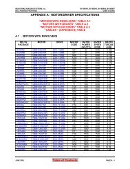
Table 1.1 - Configuration Switch and Code Bit Settings<br />
Configuration<br />
Switch<br />
Settings<br />
Resolver Type<br />
Controller<br />
Type<br />
Resolution<br />
(Bit)<br />
Bits per<br />
Revolution<br />
MAX<br />
Resolver<br />
Shaft Speed<br />
(RPM)<br />
Description<br />
0<br />
1<br />
2<br />
3 *<br />
4 *<br />
5 *<br />
6 *<br />
7<br />
8<br />
9<br />
A<br />
B*<br />
C*<br />
D*<br />
E*<br />
F<br />
12<br />
14<br />
16<br />
12<br />
12<br />
12<br />
12<br />
10<br />
12<br />
14<br />
16<br />
12<br />
12<br />
12<br />
12<br />
10<br />
4096<br />
16384<br />
65536<br />
4096<br />
4096<br />
4096<br />
4096<br />
1024<br />
4096<br />
16384<br />
65536<br />
4096<br />
4096<br />
4096<br />
4096<br />
1024<br />
3600<br />
900<br />
225<br />
N/A<br />
N/A<br />
N/A<br />
N/A<br />
14400<br />
3600<br />
900<br />
225<br />
N/A<br />
N/A<br />
N/A<br />
N/A<br />
14400<br />
12 Bit Mode<br />
14 Bit Mode<br />
16 Bit Mode<br />
Test Mode 100 CW<br />
Test Mode 1000 CW<br />
Test Mode 100 CCW<br />
Test Mode 1000 CCW<br />
10 Bit Mode<br />
12 Bit Mode<br />
14 Bit Mode<br />
16 Bit Mode<br />
Test Mode 100 CW<br />
Test Mode 1000 CW<br />
Test Mode 100 CCW<br />
Test Mode 1000 CCW<br />
10 Bit Mode<br />
MSC<br />
MSC<br />
MSC<br />
MSC<br />
MSC<br />
MSC<br />
MSC<br />
DELTAMAX<br />
DELTAMAX<br />
DELTAMAX<br />
DELTAMAX<br />
DELTAMAX<br />
DELTAMAX<br />
DELTAMAX<br />
DELTAMAX<br />
MSC<br />
*<br />
Test Modes which simulate a resolver turning at the noted speed and direction to simulate<br />
Master Resolver Motion or Trouble Shooting.<br />
AUGUST 1998 PAGE 3 OF 10
IB-11B032<br />
INSTRUCTION MANUAL<br />
IV. FUNCTIONAL TEST FOR <strong>RFC</strong>-<strong>240X</strong><br />
INDUSTRIAL INDEXING SYSTEMS, Inc.<br />
<strong>RFC</strong>-<strong>240X</strong> RESOLVER/FIBER OPTIC CONVERTER<br />
1. For the <strong>RFC</strong>-<strong>240X</strong>, set a Multimeter to a scale to read 24V DC.<br />
2. Turn on the system power.<br />
3. For the <strong>RFC</strong>-<strong>240X</strong>, verify 24V DC ± 10% from P2-1 to P2-2.<br />
4. If the voltage is within specification, then continue with the next step. If the voltage is<br />
out of specification, then correct the voltage supply before proceeding.<br />
5. Set a multimeter to the 10V AC scale.<br />
6. Connect the meter leads to P1-7 and P1-8 (white and black wires of C-200YYY cable,<br />
(see Figure 3).<br />
7. The meter should indicate 8V AC ± 1V AC.<br />
8. If an out of specification reading is obtained, remove P1 from the controller and connect<br />
the meter's leads to ROHI and GND test points on the <strong>RFC</strong>-<strong>240X</strong>.<br />
9. The meter should indicate 8V AC ± 1V AC.<br />
10. If an out of specification reading is still obtained, replace the <strong>RFC</strong>-<strong>240X</strong>. If readings are<br />
correct, then go on to the next step<br />
11. With the 9-pin connector P1 connected to the <strong>RFC</strong>-<strong>240X</strong>, connect the meter leads to<br />
P1-1 and P1-2 (see Figure 3).<br />
12. While observing the meter, rotate the motor shaft one full revolution. The voltage<br />
should rise to 8V AC ± 2V AC and fall to less than 1V AC twice per revolution.<br />
13. With P1 connected to the <strong>RFC</strong>-<strong>240X</strong> connect the meter leads to P1-4 and P1-5 (see<br />
Figure 3).<br />
14. While observing the meter, rotate the motor shaft one full revolution. The voltage<br />
should rise to 8V AC ± 2V AC and fall to less than 1V AC twice per revolution.<br />
15. If an out of specification reading is obtained, go on to the next step. If the readings are<br />
correct, then go to Step 17.<br />
16. Turn off power to the system.<br />
17. Remove 9-pin connector P2 from the <strong>RFC</strong>-<strong>240X</strong>.<br />
18. Set the multimeter to measure ohms (W).<br />
19. Measure ohms (W) from connector P2-1 to P2-2. The reading should be between 20W<br />
and 300W.<br />
PAGE 4 OF 10 AUGUST 1998
INDUSTRIAL INDEXING SYSTEMS, Inc.<br />
<strong>RFC</strong>-<strong>240X</strong> RESOLVER/FIBER OPTIC CONVERTER<br />
IV. FUNCTIONAL TEST FOR <strong>RFC</strong>-<strong>240X</strong> (Cont’d)<br />
IB-11B032<br />
INSTRUCTION MANUAL<br />
20. Measure ohms (W) from connector P2-4 to P2-5. The reading should be between 20W<br />
and 300W.<br />
21. Measure ohms (W) from connector P2-7 to P2-8. The reading should be between 20W<br />
and 300W.<br />
22. Measure P2-1 thru P2-9 to earth ground (panel). None of the P2-X connections should<br />
have less than 10KW<br />
23. Measure P2-1 to all other pins in the P2 connector. All readings should be greater than<br />
10KW.<br />
24. Measure P2-4 to all other pins in the P2 connector. All readings should be greater than<br />
10KW.<br />
25. Measure P2-7 to all other pins in the P2 connector. All readings should be greater than<br />
10KW.<br />
26. If there are any problems with steps 19 thru 25, then thoroughly ring out the resolver<br />
cable C-200YYY (see Figure 5) for continuity, shorts, and opens. If no problems are<br />
found with the cable, then replace the resolver.<br />
27. Turn the system power ON. Then disconnect the Fiber Optic Cable from the Fiber<br />
Optic Transmitter on the <strong>RFC</strong>-<strong>240X</strong>.<br />
28. Verify a red glow emanating from the Fiber Optic Transmitter.<br />
29. If there is no glow, then replace the <strong>RFC</strong>-<strong>240X</strong>. If a red glow is present, go on to the<br />
next step.<br />
30. Reconnect the Fiber Optic Cable to the Fiber Optic Transmitter on the <strong>RFC</strong>-<strong>240X</strong>.<br />
31. Disconnect the opposite end of the Fiber Optic Cable from the motion controller.<br />
32. Verify a red glow emanating from the end of the Fiber Optic Cable.<br />
33. If there is no glow, then replace the Fiber Optic Cable. If a red glow is present, go to<br />
the next step.<br />
34. Slowly rotate the resolver shaft. The LSB0 and LSB1 LEDs on the <strong>RFC</strong>-<strong>240X</strong> should<br />
toggle on and off with slow rotations of the shaft (see Figure 1). The MSB LED should<br />
be on for 180° of shaft rotation, and off for 180° of shaft rotation.<br />
AUGUST 1998 PAGE 5 OF 10
IB-11B032<br />
INDUSTRIAL INDEXING SYSTEMS, Inc.<br />
INSTRUCTION MANUAL<br />
<strong>RFC</strong>-<strong>240X</strong> RESOLVER/FIBER OPTIC CONVERTER<br />
IV. FUNCTIONAL TEST FOR <strong>RFC</strong>-<strong>240X</strong> (Cont’d)<br />
Figure 1 - LED Table<br />
35. If the LEDs are not working properly, then replace the <strong>RFC</strong>-<strong>240X</strong>.<br />
36. If the LED tests are good, then any other problems that occur may be from the Fiber<br />
Optic Receiver end of the Motion Controller, or the Motion Control software.<br />
V. SETTING RESOLVER 0.0 SHAFT ANGLE<br />
1. Slowly rotate the resolver shaft CW while observing the LSB0, LSB1, and MSB LEDs<br />
on the <strong>RFC</strong>-<strong>240X</strong>.<br />
2. Continue to rotate the shaft CW until the MSB LED is turned from ON to OFF (see<br />
Figure 1). At the toggling point of the MSB LED, the resolver is at 0.0 shaft angle.<br />
PAGE 6 OF 10 AUGUST 1998
INDUSTRIAL INDEXING SYSTEMS, Inc.<br />
<strong>RFC</strong>-<strong>240X</strong> RESOLVER/FIBER OPTIC CONVERTER<br />
IB-11B032<br />
INSTRUCTION MANUAL<br />
Figure 2 - <strong>RFC</strong>-<strong>240X</strong> Layout<br />
AUGUST 1998 PAGE 7 OF 10
IB-11B032<br />
INSTRUCTION MANUAL<br />
INDUSTRIAL INDEXING SYSTEMS, Inc.<br />
<strong>RFC</strong>-<strong>240X</strong> RESOLVER/FIBER OPTIC CONVERTER<br />
Figure 3 - Connection Interconnection<br />
PAGE 8 OF 10 AUGUST 1998
INDUSTRIAL INDEXING SYSTEMS, Inc.<br />
<strong>RFC</strong>-<strong>240X</strong> RESOLVER/FIBER OPTIC CONVERTER<br />
IB-11B032<br />
INSTRUCTION MANUAL<br />
Figure 4 - Fiber Optic Link Cable, C-966YYY<br />
Figure 5 - C-200YYY Cable<br />
AUGUST 1998 PAGE 9 OF 10
IB-11B032<br />
INSTRUCTION MANUAL<br />
INDUSTRIAL INDEXING SYSTEMS, Inc.<br />
<strong>RFC</strong>-<strong>240X</strong> RESOLVER/FIBER OPTIC CONVERTER<br />
PAGE 10 OF 10 AUGUST 1998
IB-11B032<br />
INDUSTRIAL<br />
INDEXING SYSTEMS<br />
INC.<br />
626 FISHERS RUN<br />
VICTOR, NEW YORK 14564<br />
(585) 924-9181<br />
FAX (585) 924-2169<br />
PRINTED IN USA<br />
© 1998