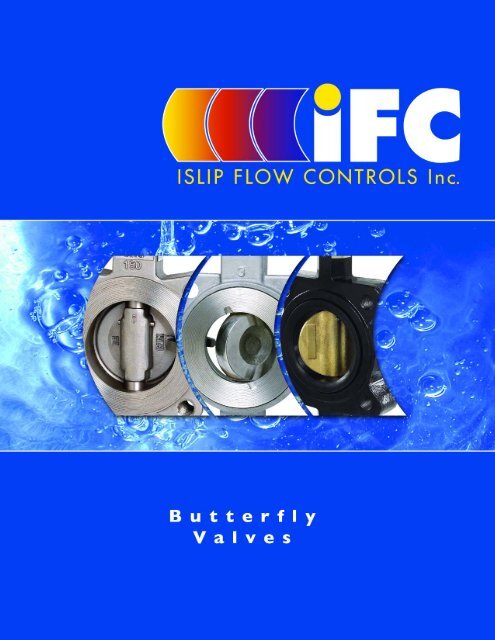
Butterfly Valves - ISLIP Flow Controls
Butterfly Valves - ISLIP Flow Controls
Butterfly Valves - ISLIP Flow Controls

You also want an ePaper? Increase the reach of your titles
YUMPU automatically turns print PDFs into web optimized ePapers that Google loves.
Table Of Contents<br />
IFC Series BI125W/L Resilient Seated <strong>Butterfly</strong> <strong>Valves</strong><br />
Design Features . . . . . . . . . . . . . . . . . . . . . . . . . . . . . . . . . . . . . . . . . . . . . . . . . . . .2<br />
Valve Construction Data . . . . . . . . . . . . . . . . . . . . . . . . . . . . . . . . . . . . . . . . . . . .3<br />
Valve Sizing Data . . . . . . . . . . . . . . . . . . . . . . . . . . . . . . . . . . . . . . . . . . . . . . . . . . .4<br />
CV Values (US-GPM @ 1 PSID) . . . . . . . . . . . . . . . . . . . . . . . . . . . . . . . . . . . . .4<br />
Method of Calculating <strong>Flow</strong> . . . . . . . . . . . . . . . . . . . . . . . . . . . . . . . . . . . . . . . .4<br />
Valve Seating Torque (In.-Lbs.) . . . . . . . . . . . . . . . . . . . . . . . . . . . . . . . . . . . . . .4<br />
Valve Dimensions - Sizes 2” - 24” . . . . . . . . . . . . . . . . . . . . . . . . . . . . . . . . . . . . .5<br />
Valve Dimensions - Sizes 30” - 48” . . . . . . . . . . . . . . . . . . . . . . . . . . . . . . . . . . . .6<br />
Manual Actuator Dimensions . . . . . . . . . . . . . . . . . . . . . . . . . . . . . . . . . . . . . . . . .6<br />
Required Bolt Lengths . . . . . . . . . . . . . . . . . . . . . . . . . . . . . . . . . . . . . . . . . . . . . .7<br />
Valve Weights . . . . . . . . . . . . . . . . . . . . . . . . . . . . . . . . . . . . . . . . . . . . . . . . . . . . .7<br />
Material Selection Guide . . . . . . . . . . . . . . . . . . . . . . . . . . . . . . . . . . . . . . . . . . . .8<br />
Installation and Maintenance Instructions . . . . . . . . . . . . . . . . . . . . . . . . . . . . . . .9<br />
How to Order . . . . . . . . . . . . . . . . . . . . . . . . . . . . . . . . . . . . . . . . . . . . . . . . . . .10<br />
IFC Series BH150W/L High Performance <strong>Butterfly</strong> <strong>Valves</strong><br />
Design Features . . . . . . . . . . . . . . . . . . . . . . . . . . . . . . . . . . . . . . . . . . . . . . . . . .11<br />
Principles of Operation . . . . . . . . . . . . . . . . . . . . . . . . . . . . . . . . . . . . . . . . . . . .12<br />
Valve Construction Data . . . . . . . . . . . . . . . . . . . . . . . . . . . . . . . . . . . . . . . . . . .13<br />
Standards of Construction . . . . . . . . . . . . . . . . . . . . . . . . . . . . . . . . . . . . . . . .13<br />
Pressure-Temperature Ratings . . . . . . . . . . . . . . . . . . . . . . . . . . . . . . . . . . . . .13<br />
Valve Sizing Data . . . . . . . . . . . . . . . . . . . . . . . . . . . . . . . . . . . . . . . . . . . . . . . . . .14<br />
CV Values (US-GPM @ 1 PSID) . . . . . . . . . . . . . . . . . . . . . . . . . . . . . . . . . . . .14<br />
Method of Calculating <strong>Flow</strong> . . . . . . . . . . . . . . . . . . . . . . . . . . . . . . . . . . . . . . .14<br />
Valve Breakaway Torque (In.-Lbs.) . . . . . . . . . . . . . . . . . . . . . . . . . . . . . . . . . .14<br />
Valve Dimensions - Sizes 2 1 / 2 ” - 12” . . . . . . . . . . . . . . . . . . . . . . . . . . . . . . . . . .15<br />
Manual Actuator Dimensions . . . . . . . . . . . . . . . . . . . . . . . . . . . . . . . . . . . . . . . .15<br />
Required Bolt Lengths . . . . . . . . . . . . . . . . . . . . . . . . . . . . . . . . . . . . . . . . . . . . .16<br />
Valve Weights . . . . . . . . . . . . . . . . . . . . . . . . . . . . . . . . . . . . . . . . . . . . . . . . . . . .16<br />
Installation and Maintenance Instructions . . . . . . . . . . . . . . . . . . . . . . . . . . . . .17<br />
How to Order . . . . . . . . . . . . . . . . . . . . . . . . . . . . . . . . . . . . . . . . . . . . . . . . . . .18<br />
IFC Series BDC/BDI High Performance Damper <strong>Butterfly</strong><br />
<strong>Valves</strong><br />
Valve Construction Data . . . . . . . . . . . . . . . . . . . . . . . . . . . . . . . . . . . . . . . . . . .19<br />
Valve Dimensions - Sizes 3” - 60” . . . . . . . . . . . . . . . . . . . . . . . . . . . . . . . . . . . .20<br />
Valve Operating Data . . . . . . . . . . . . . . . . . . . . . . . . . . . . . . . . . . . . . . . . . . . . . .21<br />
How to Order . . . . . . . . . . . . . . . . . . . . . . . . . . . . . . . . . . . . . . . . . . . . . . . . . . .22<br />
Limited Warranty<br />
All products are warranted to be free of defects in<br />
material and workmanship for a period of one year<br />
from the date of shipment, subject to the limitations<br />
below: If the purchaser believes a product defective,<br />
the purchaser shall: (a) Notify the manufacturer, state<br />
the alleged defect and request permission to return<br />
the product. (b) If permission is given, return the<br />
product with transportation prepaid. If the product is<br />
accepted for return and found to be defective, the<br />
manufacturer will, at its discretion, either repair or<br />
Notes: The material in this catalogue is for general information. For specific performance data and proper<br />
material selection, consult factory or your IFC representative. Although every attempt has been made<br />
to ensure that the information contained in this catalogue is correct IFC Inc. reserves the right to change<br />
designs, materials and/or specifications without notice.<br />
replace the product, f.o.b. factory, within 60 days of<br />
receipt, or refund the purchase price.<br />
Other than to repair, replace or refund described<br />
above, the purchaser agrees that the manufacturer<br />
shall not be liable for any loses, costs, expenses or<br />
damages of any kind arising out of the product,<br />
its use, installation or replacement, labeling,<br />
instructions, information or technical data of any<br />
kind, description of product use, sample or model,<br />
warnings or lack of foregoing. No other warranties,<br />
written or oral, expressed or implied, including the<br />
warranties of fitness for a particular purpose and<br />
merchantability, are made or authorized.<br />
No affirmation of fact, promise, description of<br />
product use or sample or model shall create any<br />
warranty from the manufacturer, unless signed<br />
by the president. These products are not<br />
manufactured, sold or intended for personal, family<br />
or household purposes.<br />
1 Tel. 905-335-8777 Fax. 905-335-0977 Toll Free Tel. 1-866-872-0072 Toll Free Fax. 1-866-872-0073
IFC Series BI125W/L<br />
Design Features<br />
A<br />
B<br />
C<br />
D<br />
E<br />
F<br />
ISO 5211 (Part I &<br />
II) Mounting Pad<br />
Designed for universal<br />
adaptation of pneumatic or<br />
electric actuators, gear<br />
operators and handles.<br />
O-Ring<br />
Secondary shaft seal.<br />
Name Plate<br />
Permanently attached<br />
to body providing disc,<br />
seat and shaft material<br />
identification.<br />
Bushings<br />
Four (4) bushings are<br />
used to provided<br />
maximum shaft support<br />
and centralized alignment<br />
of the one-piece shaft.<br />
Body<br />
Available in full lug<br />
and wafer style.<br />
One-piece thru -<br />
shaft<br />
The blow-out proof<br />
shaft design delivers<br />
positive disc-to-seat<br />
location while offering<br />
maximum strength.<br />
A<br />
B<br />
C<br />
D<br />
E<br />
F<br />
G<br />
H<br />
I<br />
J<br />
J<br />
G<br />
H<br />
Pinned Disc<br />
The disc is attached to the<br />
shaft by pins that provide a<br />
solid mechanical connection.<br />
Disc<br />
Disc edge is machined and<br />
polished 360° to assure leakproof<br />
positive shut-off while<br />
minimizing operating torque.<br />
I<br />
Phenolic Backed Seat<br />
Provides additional support<br />
making the seat noncollapsible.<br />
360° sealing<br />
protects components from<br />
media and provides the<br />
primary shaft seal. Flange<br />
gaskets are not required.<br />
Shaft Seal<br />
The bi-directional shaft seal prevents<br />
external contamination of the stem<br />
area while providing a back-up for<br />
the primary shaft seal formed by the<br />
disc/seat interface.<br />
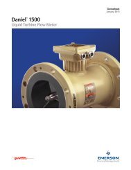
The IFC series BI125W/L butterfly valve is available in sizes<br />
2” thru 48”, wafer or lug body design. These valves were<br />
designed to meet the stringent requirements for HVAC, Oil<br />
& Gas and Industrial applications, or wherever positive shutoff<br />
is required for liquids, gases and slurries.<br />
Incorporating a 200 psig pressure rating for sizes 2” thru<br />
12” and 150 psig pressure rating for sizes 14” thru 48” the<br />
IFC series BI125W/L valves are constructed with a cast iron<br />
or ductile iron body and stainless steel shafts.The discs and<br />
seats are available in a wide range of materials to meet your<br />
specific application needs.<br />
These valves are designed and manufactured for use with<br />
ANSI 125 or 150 class flanges and generally designed in<br />
accordance with API 609 (Except for the 16” to 20” face-toface<br />
dimensions) and MSS-SP-67.<br />
Tel. 905-335-8777 Fax. 905-335-0977 Toll Free Tel. 1-866-872-0072 Toll Free Fax. 1-866-872-0073<br />
2
IFC Series BI125W/L<br />
Valve Construction Data<br />
5<br />
6<br />
1<br />
3<br />
4<br />
2<br />
7<br />
Material Specifications<br />
Part Part<br />
Material<br />
No. Name Description Specifications<br />
1 Body Cast Iron ASTM A126-B<br />
Ductile Iron ASTM A536 65-45-12<br />
2 Disc Ductile Iron Electrolytic Nickel Plated ASTM A536 65-45-12<br />
Aluminum Bronze<br />
ASTM B148 C954<br />
Type 316 Stainless Steel<br />
ASTM A351-CF8M<br />
3 Shaft Type 416 Stainless Steel ASTM A582<br />
Type 316 Stainless Steel 2<br />
ASTM A276<br />
4 Seat Buna-N (-10°F to 180°F)<br />
EPDM (-10°F to 225°F)<br />
Viton 26B (-10°F to 275°F)<br />
Teflon lined EPDM (-10°F to 225°F)<br />
5 Bushings x 4 Teflon Impregnated Fiberglass Backed<br />
6 Seal Buna-N O-Ring<br />
7 Pin Type 316 Stainless Steel 4,5<br />
Key Carbon Steel (Sizes 12” - 48”)<br />
Screws 18-8 Stainless Steel 1 (Optional)<br />
Notes: 1. Dead end service screws are standard on lug body valves only.<br />
2. <strong>Valves</strong> with 316SS (Stainless Steel) discs are only available with 316SS shafts.<br />
3. Do not use EPDM when hydrocarbons are present.<br />
4. Valve sizes 6” and larger are equipped with two (2) pins.<br />
5. Valve sizes 4” and smaller are equipped with one (1) pin.<br />
Standards of Construction<br />
IFC BI125W/L Pressure Temperature Chart<br />
Component Standard<br />
General Design API 609<br />
300<br />
Mounting Pad ISO 5211<br />
Laying Length API 609, MSS SP-67, ISO 5752<br />
275<br />
MAX. TEMP. VITON<br />
Inspection and Testing API 598<br />
Upper Pressure Limits (Non-Shock)<br />
Valve Size<br />
M.A.W.P.<br />
2” - 12” (50-300 mm) 200 psig (13.79 bars)<br />
14” - 48” (350-1200 mm) 150 psig (10.34 bars)<br />
Temperature (°F)<br />
250<br />
225<br />
200<br />
MAX. TEMP. EPDM<br />
SIZES 30"-48"<br />
SIZES 14"-24"<br />
SIZES 2"-12"<br />
Note:<strong>Valves</strong> rated for full vacuum service.<br />
Velocity Limits<br />
175<br />
MAX. TEMP. BUNA-N<br />
180<br />
Fluids<br />
30 ft/s (10 m/s)<br />
Gases<br />
200 ft/s (65 m/s)<br />
Note: For greater velocities consult factory.<br />
150<br />
0 50 100 150<br />
200<br />
Pressure (Psig)<br />
3 Tel. 905-335-8777 Fax. 905-335-0977 Toll Free Tel. 1-866-872-0072 Toll Free Fax. 1-866-872-0073
IFC Series BI125W/L<br />
Valve Sizing Data<br />
Cv Values (US-GPM @ 1 Psid)<br />
Size<br />
DISC POSITION (Degrees)<br />
in. 10¡ 20¡ 30¡ 40¡ 50¡ 60¡ 70¡ 80¡ 90¡<br />
2” 0.1 5 12 24 45 64 90 125 135<br />
2 1 / 2 ” 0.2 8 20 37 65 89 144 204 220<br />
3” 0.3 12 22 39 70 116 183 275 302<br />
4” 0.5 17 36 78 139 230 364 546 600<br />
5” 0.8 29 61 133 237 392 620 930 1022<br />
6” 2 45 95 205 366 605 958 1437 1579<br />
8” 3 89 188 408 727 1202 1903 2854 3136<br />
10” 4 151 320 694 1237 2047 3240 4859 5340<br />
12” 5 234 495 1072 1911 3162 5005 7507 8250<br />
14” 6 338 715 1549 2761 4568 7230 10844 11917<br />
16” 8 464 983 2130 3797 6282 9942 14913 16388<br />
18” 11 615 1302 2822 5028 8320 13168 19752 21705<br />
20” 14 791 1674 3628 6465 10698 16931 25396 27908<br />
24” 22 1222 2587 5605 9989 16528 26157 39236 43116<br />
30” 40 2036 4089 7461 11777 17578 26634 40975 58121<br />
36” 60 3021 6063 11055 17449 26086 39731 60895 86375<br />
42” 101 4738 9514 17361 27405 40903 61974 95344 135240<br />
48” 134 6188 12426 22675 35794 53424 80945 124531 176640<br />
Method Of Calculating <strong>Flow</strong><br />
Liquid <strong>Flow</strong><br />
QL = Cv<br />
∆P<br />
g<br />
QL = flow rate of liquid (gal./min.)<br />
∆P = differential pressure across the valve (psi)<br />
g = specific gravity of liquid: water = 1.000<br />
Gas <strong>Flow</strong><br />
For non-critical flow (<br />
∆P<br />
IFC Series BI125W/L<br />
Dimensions - Sizes 2 to 24<br />
ØF<br />
ØF<br />
G<br />
D<br />
D<br />
DISC CHORDAL DIMENSIONS<br />
ØJ<br />
ØE<br />
PORT<br />
C<br />
A<br />
B<br />
O-BCD<br />
4-QTY.<br />
R-DIA.<br />
WAFER BODY<br />
ØL<br />
A<br />
B<br />
O-BCD<br />
P-QTY.<br />
Q-DIA.<br />
<br />
LUG BODY<br />
H-DIA.<br />
MOUNTING DETAIL<br />
S-KEYWAY<br />
SIZE<br />
H-DIA.<br />
M-BCD<br />
4 QTY.<br />
N-SIZE<br />
K<br />
ACROSS<br />
FLATS<br />
Valve Dimensions<br />
Size A B C D E F G H J K L M N O P Q R S<br />
in. in. in. in. in. in. in. in. in. in. in. in. in. in. in. in. in. in.<br />
(mm)(mm) (mm) (mm) (mm) (mm) (mm) (mm) (mm) (mm) (mm) (mm) (mm) (mm) (mm)<br />
(mm)<br />
2” 10.75 6.34 1.66 1.25 2.09 3.00 1.25 0.50 3.94 0.349 4.00 1.97 0.276 4.75 4 5 /8 ”-11UNC 0.687 –<br />
50 273 161 42 32 53 76 32 13 100 9 102 50 7 121 17<br />
2 1 / 2 ” 11.65 6.89 1.75 1.25 2.54 3.00 1.84 0.50 4.75 0.349 4.75 1.97 0.276 5.50 4 5 /8 ”-11UNC 0.687 –<br />
65 296 175 44 32 65 76 47 13 121 9 121 50 7 140 17<br />
3” 12.12 7.13 1.78 1.25 3.13 3.00 2.50 0.50 5.00 0.349 5.13 1.97 0.276 6.00 4 5 /8 ”-11UNC 0.687 –<br />
75 308 181 45 32 80 76 64 13 127 9 130 50 7 152 17<br />
4” 13.62 7.87 2.06 1.25 4.13 3.63 3.50 0.63 6.13 0.437 6.75 2.76 0.394 7.50 8 5 /8 ”-11UNC 0.687 –<br />
100 346 200 52 32 105 92 89 16 156 11 171 70 10 191 17<br />
5” 14.65 8.39 2.14 1.25 4.86 3.63 4.38 0.75 7.50 0.500 7.75 2.76 0.394 8.50 8 3 /4 ”-10UNC 0.812 –<br />
125 372 213 54 32 123 92 111 19 191 13 197 70 10 216 21<br />
6” 15.63 8.90 2.19 1.25 6.13 3.63 5.75 0.75 8.38 0.500 8.63 2.76 0.394 9.50 8 3 /4 ”-10UNC 0.812 –<br />
150 397 226 56 32 156 92 146 19 213 13 219 70 10 241 21<br />
8” 18.90 10.25 2.39 1.75 8.00 4.50 7.63 0.88 10.57 0.625 10.56 4.01 0.472 11.75 8 3 /4 ”-10UNC 0.812 –<br />
200 480 260 61 44 203 114 194 22 268 16 268 102 12 298 21<br />
10” 21.25 11.50 2.58 1.75 9.87 4.50 9.50 1.13 12.81 0.812 10.06 4.01 0.472 14.25 12 7 / 8 ”-9UNC 0.937 –<br />
250 540 292 66 44 251 114 241 29 325 21 256 102 12 362 24<br />
12” 24.57 13.27 3.03 1.75 11.87 5.50 11.50 1.25 15.88 – 16.00 4.01 0.472 17.00 12 7 / 8 ”-9UNC 0.937 0.25 X 1.00<br />
300 624 337 77 44 301 140 292 32 403 406 102 12 432 24<br />
14” 26.75 14.50 3.00 1.75 13.13 5.50 12.81 1.25 17.19 – 17.13 4.01 0.472 18.75 12 1”-8UNC 1.062 0.25 X 1.00<br />
350 679 368 76 44 334 140 325 32 437 435 102 12 476 27<br />
16” 29.94 15.75 3.41 2.00 15.38 7.75 15.00 1.30 19.21 – 20.00 5.51 0.709 21.25 16 1”-8UNC 1.062 0.31 X 1.57<br />
400 760 400 87 51 391 197 381 33 488 508 140 18 540 27<br />
18” 31.56 16.61 4.16 2.00 17.38 7.75 16.87 1.50 21.22 – 21.38 5.51 0.709 22.75 16 1 1 / 8 ”-7UNC 1.250 0.37 X 1.81<br />
450 802 422 106 51 441 197 428 38 539 543 140 18 578 32<br />
20” 35.65 18.90 5.19 2.53 19.38 7.75 18.69 1.63 23.38 – 23.31 5.51 0.709 25.00 20 1 1 / 8 ”-7UNC 1.250 0.37 X 1.81<br />
500 906 480 132 64 492 197 475 41 594 592 140 18 635 32<br />
24” 42.97 22.13 6.00 2.75 23.31 10.88 22.58 2.00 32.13 – 27.88 6.49 0.906 29.50 20 1 1 / 4 ”-7UNC 1.375 0.5 X 2.36<br />
600 1091 562 152 70 592 276 574 51 816 708 165 23 749 35<br />
Notes: 1. Quantity P and dimension Q refer to lug style. Dimension R refers to wafer style.<br />
2. Dimension C is the installed dimension.Approximately 1 / 8 ” wider when relaxed.<br />
3. <strong>Valves</strong> designed for installation between ASME B16.1 Class 125 and ASME B16.5 Class 150 flanges.<br />
4. Gaskets are not required and should not be used.<br />
5 Tel. 905-335-8777 Fax. 905-335-0977 Toll Free Tel. 1-866-872-0072 Toll Free Fax. 1-866-872-0073
IFC Series BI125W/L<br />
Dimensions - Sizes 30 to 48<br />
ØF<br />
ØF<br />
G<br />
D<br />
O-BCD<br />
P-QTY.<br />
Q-DIA.<br />
D<br />
DISC CHORDAL DIMENSION<br />
ØJ<br />
ØE<br />
PORT<br />
A<br />
B<br />
O-BCD<br />
4-QTY.<br />
R-DIA.<br />
A<br />
ØL<br />
A<br />
A<br />
B<br />
O-BCD<br />
S-QTY.<br />
R-DIA.<br />
ØL<br />
H-DIA.<br />
<br />
T-KEYWAY<br />
SIZE<br />
M-BCD<br />
8-QTY.<br />
N-SIZE<br />
MOUNTING DETAIL<br />
K<br />
C<br />
WAFER BODY<br />
LUG BODY<br />
SECTION A-A<br />
Valve Dimensions<br />
Size A B C D E F G H J K L M N O P Q R S T<br />
in in in in in in in in in in in in in in in in<br />
(mm) (mm) (mm) (mm) (mm) (mm) (mm) (mm) (mm) (mm) (mm) (mm) (mm) (mm) (mm) (mm)<br />
30” 50.56 26.00 6.56 2.63 28.56 11.81 27.75 2.50 31.28 2.13 38.75 10.00 0.708 36.00 24 1.38 1 1 / 4 ”-7UNC-2B 28 0.71 X 2.48<br />
750 1284 660 167 67 725 300 705 63 795 54 984 254 18 914 35<br />
36” 58.53 28.38 8.00 4.63 33.13 11.81 32.00 2.94 37.28 2.38 46.00 10.00 0.708 42.75 28 1.63 1 1 / 2 ”-6UNC-2B 32 0.79 X 3.94<br />
900 1487 721 203 118 842 300 813 75 974 60 1168 254 18 1086 41<br />
42” 70.25 33.75 9.88 5.91 39.31 11.81 38.00 3.75 44.25 2.63 53.00 10.00 0.708 49.50 32 1.63 1 1 / 2 ”-6UNC-2B 36 0.98 X 5.51<br />
1050 1785 857 251 150 998 300 965 95 1124 67 1346 254 18 1257 41<br />
48” 76.91 37.00 10.88 5.91 44.38 13.75 42.91 4.13 49.75 2.75 59.50 11.75 0.866 56.00 40 1.63 1 1 / 2 ”-6UNC-2B 44 1.10 X 5.51<br />
1200 1954 940 276 150 1127 349 1090 105 1264 70 1511 298 22 1422 41<br />
Notes: 1. Quantity S and dimension R refer to lug style. Quantity P and dimension Q refer to wafer style.<br />
2. Dimension C is the installed dimension. Approximately 3 / 8 ” wider when relaxed.<br />
3. <strong>Valves</strong> designed for installation between ASME B16.1 class 125 and ASME B16.47 series A class 150 flanges.<br />
4. Gasket are not required and should not be used.<br />
Manual Actuator Dimensions<br />
A<br />
B<br />
C<br />
H<br />
A<br />
B<br />
F<br />
G<br />
E<br />
D<br />
Lever<br />
Valve Size A B Weight<br />
in in in Lb.<br />
(mm) (mm) (mm) (Kg)<br />
2” - 6” 10.0 1.0 3.0<br />
50 - 150 252 24 1.4<br />
8” - 12” 14.1 1.4 4.0<br />
100 - 300 359 36 1.8<br />
Notes:<br />
It is recommended that handles be used thru<br />
8” valve size for liquid or rated pressure<br />
service. 10” - 12” valves with handles should<br />
only be used on gas and low pressure<br />
applications.<br />
Gear<br />
Valve Size Ratio A B C D E F G H Weight<br />
in in in in in in in in in Lb.<br />
(mm) (mm) (mm) (mm) (mm) (mm) (mm) (mm) (mm) (Kg)<br />
2” - 6” 24:1 5.0 1.7 1.1 4.1 1.6 2.6 6.0 7.6 10<br />
50-150 127 45 28 105 41 66 152 193 4.5<br />
8” - 10” 30:1 7.0 2.6 1.3 6.0 1.8 3.3 12.0 12.5 28<br />
200-250 178 66 34 152 46 84 305 318 12.7<br />
12” - 14” 50:1 7.8 3.0 1.5 6.6 2.0 3.5 12.0 12.5 33<br />
300-350 198 76 38 170 51 89 305 318 15.0<br />
16” 80:1 11.5 4.4 1.6 10.3 2.5 4.6 12.0 16.2 71<br />
400 292 112 41 262 64 117 305 411 32.2<br />
18” - 24” 290:1 12.3 4.7 2.8 10.8 2.9 6.3 12.0 13.4 118<br />
450 - 600 313 120 73 274 75 162 305 342 53.5<br />
Tel. 905-335-8777 Fax. 905-335-0977 Toll Free Tel. 1-866-872-0072 Toll Free Fax. 1-866-872-0073<br />
6
IFC Series BI125W/L<br />
Required Bolt Lengths<br />
Wafer Valve - Recommended Flange Bolt Lengths<br />
Valve Bolt Length Of Fasteners (L)<br />
Size Qty. Size Threaded Studs Bolts<br />
2” 4 5 /8 ”-UNC 4 3 / 4 ” 4”<br />
2 1 / 2 ” 4 5 /8 ”-UNC 5 1 / 4 ” 4 1 / 4 ”<br />
3” 4 5 /8 ”-UNC 5 1 / 4 ” 4 1 / 2 ”<br />
4” 8 5 /8 ”-UNC 5 1 / 2 ” 4 3 / 4 ”<br />
5” 8 3 /4 ”-UNC 6” 5”<br />
6” 8 3 /4 ”-UNC 6” 5 1 / 4 ”<br />
8” 8 3 /4 ”-UNC 6 1 / 2 ” 5 3 / 4 ”<br />
10” 12 7 /8 ”-UNC 7” 6”<br />
12” 12 7 /8 ”-UNC 7 3 / 4 ” 6 3 / 4 ”<br />
14” 12 1”-UNC 8 1 / 4 ” 7”<br />
16” 16 1”-UNC 8 3 / 4 ” 7 1 / 2 ”<br />
18” 16 1 1 / 8 ”-UNC 10” 8 3 / 4 ”<br />
20” 20 1 1 / 8 ”-UNC 11” 10”<br />
24” 20 1 1 / 4 ”-UNC 12 3 / 4 ” 11 1 / 4 ”<br />
Note: Lengths are based on ANSI class 150 weld neck flanges per ASME B16.5.<br />
L<br />
THREADED STUDS<br />
L<br />
BOLTS<br />
Lug Valve - Recommended Flange Bolt Lengths<br />
Valve Bolt Length Of Fasteners (L)<br />
Size Qty. Size Threaded Studs Bolts<br />
2” 4 5 /8 ”-UNC 2 1 / 4 ” 1 1 / 4 ”<br />
2 1 / 2 ” 4 5 /8 ”-UNC 2 1 / 4 ” 1 1 / 2 ”<br />
3” 4 5 /8 ”-UNC 2 1 / 2 ” 1 1 / 2 ”<br />
4” 8 5 /8 ”-UNC 2 1 / 2 ” 1 3 / 4 ”<br />
5” 8 3 /4 ”-UNC 2 3 / 4 ” 1 3 / 4 ”<br />
6” 8 3 /4 ”-UNC 2 3 / 4 ” 1 3 / 4 ”<br />
8” 8 3 /4 ”-UNC 3” 2”<br />
10” 12 7 /8 ”-UNC 3 1 / 4 ” 2 1 / 4 ”<br />
12” 12 7 /8 ”-UNC 3 1 / 2 ” 2 1 / 2 ”<br />
14” 12 1”-UNC 3 3 / 4 ” 2 3 / 4 ”<br />
16” 16 1”-UNC 4” 3”<br />
18” 16 1 1 / 8 ”-UNC 4 3 / 4 ” 3 1 / 2 ”<br />
20” 20 1 1 / 8 ”-UNC 5 1 / 4 ” 4”<br />
24” 20 1 1 / 4 ”-UNC 6” 4 3 / 4 ”<br />
L<br />
L<br />
THREADED STUDS<br />
L<br />
L<br />
BOLTS<br />
Note: Lengths are based on ANSI class 150 weld neck flanges per ASME B16.5.<br />
IFC Series 125WB/LB Valve Weights<br />
Valve Size 2 2 1 / 2 3 4 5 6 8 10 12 14 16 18 20 24<br />
Wafer (Lb.) 6 7 10 13 18 20 32 42 70 95 117 165 275 440<br />
Wafer (Kg.) 2.7 3.2 4.5 5.9 8.2 9.1 14.5 19.0 31.7 43.1 53.1 74.8 125 200<br />
Lug (Lb.) 7 8 14 26 28 31 49 72 105 155 195 230 396 610<br />
Lug (kg.) 3.2 3.6 6.3 11.8 12.7 14.1 22.2 32.7 47.6 70.3 88.4 104 180 277<br />
Note:Valve weights refer to valve only.<br />
7 Tel. 905-335-8777 Fax. 905-335-0977 Toll Free Tel. 1-866-872-0072 Toll Free Fax. 1-866-872-0073
Material Selection Guide<br />
For Resilient Seated <strong>Valves</strong><br />
A - Recommended, B - May Be Acceptable (Testing Recommended), N - Not Recommended<br />
CORROSIVE MEDIA PS DISC MATERIALS SEAT MATERIALS CORROSIVE MEDIA PS DISC MATERIALS SEAT MATERIALS<br />
COND. DI AB 316 COND. EPDM BUNA-N COND. DI AB 316 COND. EPDM BUNA-N<br />
Acetaldehyde L
IFC Series BI125W/L Installation<br />
And Maintenance Instructions<br />
1.0 Piping and Flange Considerations<br />
The IFC Series BI125W/L butterfly valves are to be installed<br />
between pipeline flanges that conform to ASME B16.1 Class 125<br />
or ASME B16.5 Class 150. The use of slip-on or weld neck flanges<br />
has no effect on the pressure temperature rating of the valves.<br />
2.0 Installation<br />
Prior to installation, inspect valve and mating flanges to assure<br />
gasket surfaces are free of defects. Remove all foreign material<br />
such as weld spatter, oil, grease and dirt from the valve, flanges<br />
and pipeline. Do not mount valves between flanges having<br />
defective gasket surfaces.<br />
A. Check the distance between pipe flanges to ensure<br />
clearance for valve. Check piping for proper alignment.<br />
B. Place valve so that the disc has been positioned to a partially open<br />
position, with the disc edge about 1 / 4” to 3 / 8” from the face of the<br />
seat (approximately 10° open). In general, IFC recommends that<br />
the valve be installed with the stem in the vertical position and the<br />
actuator mounted directly above the valve.<br />
C.Check valve for proper alignment<br />
- On wafer valves, visually center the valve with respect to<br />
the flange faces.<br />
- Center lugged valves with the flange bolting. Never use<br />
lugged butterfly valves to align improperly positioned piping.<br />
D. Operate the valve to assure that no binding or interference exists.<br />
E. Tighten flange bolting evenly in a crisscross pattern.The flange<br />
joint is complete when there are no gaps between the valve<br />
body and the flange faces. Bolting should then be tightened<br />
sufficiently to prevent loosening.<br />
The following additional procedures should be observed when<br />
installing butterfly valves between welding flanges.<br />
A. Assemble inlet and outlet flanges to the valve body and tighten.<br />
B. Align the flange/body/flange assembly to the pipe in which<br />
the valve is being installed.<br />
C.Tack weld flanges to the pipe.<br />
D. After tack welding, remove the bolts and valve from the pipe<br />
flanges and complete the welding of the valve installation flanges.<br />
Important: To prevent seat damage, allow the flanges to<br />
cool before final installation of the butterfly valve.<br />
3.0 Valve Removal<br />
Warning: Pipeline pressure can cause personal<br />
injury or equipment damage. Relieve pipeline<br />
pressure before loosening flange bolts and<br />
disable/lock valve actuator before valve removal.<br />
A. Discontinue pipeline flow,relieve pressure where the valve is<br />
located in the pipeline and close the valve.<br />
B. If the actuator is powered, disconnect and lock out the<br />
power to prevent accidental operation of the actuator.<br />
C.Support the valve and remove the mounting bolts or studs.<br />
D. Carefully lift the valve from the pipeline.<br />
4.0 Maintenance<br />
The many IFC features minimize wear and maintenance<br />
requirements. IFC Series BI125W/L valves require no periodic<br />
maintenance or lubrication. IFC does recommend the following<br />
actions on a monthly basis:<br />
A. Operate the valve from full open to full close to assure operability.<br />
B. Check bolting for evidence of loosening and correct as required.<br />
C.Inspect flange faces and valve stem for signs of leakage.<br />
Tighten packing gland if necessary.<br />
D. Check piping and related accessories (i.e.actuator) for looseness,<br />
corrosion or defects. Correct as required.<br />
5.0 Warranty<br />
All products are warranted to be free of defects in material and<br />
workmanship for a period of one year from the date of shipment,<br />
subject to the limitations below: If the purchaser believes a product<br />
defective, the purchaser shall: (a) Notify the manufacturer, state the<br />
alleged defect and request permission to return the product. (b) If<br />
permission is given, return the product with transportation prepaid. If<br />
the product is accepted for return and found to be defective, the<br />
manufacturer will,at its discretion,either repair or replace the product,<br />
f.o.b. factory, within 60 days of receipt, or refund the purchase price.<br />
Other than to repair, replace or refund described above, the purchaser<br />
agrees that the manufacturer shall not be liable for any loses, costs,<br />
expenses or damages of any kind arising out of the product, its use,<br />
installation or replacement, labeling, instructions, information or<br />
technical data of any kind, description of product use, sample or<br />
model, warnings or lack of foregoing. No other warranties, written or<br />
oral, expressed or implied, including the warranties of fitness for a<br />
particular purpose and merchantability, are made or authorized.<br />
No affirmation of fact, promise, description of product use or<br />
sample or model shall create any warranty from the manufacturer,<br />
unless signed by the president. These products are not manufactured,<br />
sold or intended for personal, family or household purposes.<br />
9 Tel. 905-335-8777 Fax. 905-335-0977 Toll Free Tel. 1-866-872-0072 Toll Free Fax. 1-866-872-0073
How To Order<br />
Size In.<br />
Valve Type<br />
Class<br />
Body Type<br />
Body Material<br />
Disc Material<br />
Seat Material<br />
Operator<br />
8"<br />
BI = <strong>Butterfly</strong> Resilient Seated<br />
125 = 125 Lb.<br />
W = Wafer Body<br />
L = Lug Body - Dead End Service<br />
I = Cast Iron<br />
D = Ductile Iron<br />
D = Ductile Iron - Electrolytic Plated<br />
B = Aluminum Bronze<br />
SS = Type 316 Stainless Steel<br />
B = Buna-N<br />
E = EPDM<br />
T = Teflon-Lined EPDM<br />
V = Viton<br />
L = Standard 10 Position Lever Assembly<br />
LI = Infinite Position Lever Assembly<br />
G = Manual Gear<br />
E = Electric<br />
P = Pneumatic<br />
B = Bare<br />
A B C D E F<br />
G<br />
H<br />
Tel. 905-335-8777 Fax. 905-335-0977 Toll Free Tel. 1-866-872-0072 Toll Free Fax. 1-866-872-0073<br />
10
IFC Series BH150W/L<br />
Design Features<br />
A<br />
Mounting Pad<br />
The four-bolt actuator<br />
mounting pad readily accepts<br />
all types of actuation.<br />
A<br />
E<br />
Bushings<br />
High temperature fiberglass<br />
composite backed RPTFE<br />
ensuring maximum shaft support.<br />
B<br />
C<br />
Adjustable Vee-Ring<br />
Multiple Vee-Ring PTFE<br />
stem packing is adjustable<br />
and easily accessible<br />
without requiring removal<br />
of the actuator.<br />
One-Piece Shaft<br />
Constructed from 316<br />
Stainless Steel.The shaft is<br />
internally retained meeting<br />
API 609 requirements.<br />
B<br />
C<br />
D<br />
E<br />
F<br />
G<br />
H<br />
G<br />
F<br />
Seat Retainer<br />
Employs an uninterrupted<br />
gasket surface meeting API<br />
609 requirements.<br />
Disc Edge<br />
Machined and polished 360°<br />
to assure leak-proof positive<br />
shut-off. Standard material of<br />
construction is type 316<br />
Stainless Steel.<br />
D<br />
Body<br />
Available in a one-piece wafer<br />
body or lug style for dead-end<br />
service.The valves provide bidirectional<br />
sealing at full ASME<br />
Class 150 ratings.<br />
The IFC series BH150W/L high performance<br />
butterfly valve is available in sizes 2 1 / 2 " thru 12",<br />
wafer or lug body design. Available body<br />
materials are A216-WCB Carbon Steel and<br />
A351-CF8M Stainless Steel. These valves were<br />
designed to meet the stringent requirements for<br />
HVAC, Oil and Gas and Industrial applications.<br />
H<br />
Taper Pins<br />
Used to provide a solid<br />
mechanical connection<br />
between the disc and shaft.<br />
DISC OPEN<br />
SEAT<br />
SHAFT<br />
DISC CLOSED<br />
BODY<br />
The double offset shaft design assures bi-directional sealing<br />
throughout the full pressure range of the valve. The cam-like<br />
action produced by the offset disc effectively lifts the disc off<br />
the seat during the initial opening of the valve thus reducing<br />
seat wear and eliminating seat deformation. When the disc is<br />
in the open position no contact exists with the valve seat.This<br />
effectively reduces operating torques while extending seat life.<br />
11 Tel. 905-335-8777 Fax. 905-335-0977 Toll Free Tel. 1-866-872-0072 Toll Free Fax. 1-866-872-0073
IFC Series BH150W/L<br />
Principles of Operation<br />
Pressure Assisted Seat Design<br />
As the seat cross section is bellow shaped, line pressure exerts<br />
an upwards force on the seat independent of which side of the<br />
seat is under high pressure.This action forces the seat against<br />
the disc. Increased line pressure causes tighter sealing, thus<br />
ensuring bubble tight sealing at all differential pressures.<br />
Seat is non-compressed as disc approaches.<br />
Disc is closed with no line pressure.<br />
Disc in closed position; Line pressure<br />
applied from left side.<br />
Disc in closed position; Line pressure<br />
applied from right side.<br />
Sealing System Advantages<br />
The IFC Series BH150W/L <strong>Butterfly</strong> Valve incorporates an<br />
innovative seat design that ensures bi-directional bubble tight<br />
seating at all differential pressures. Advantages of the IFC<br />
sealing system include:<br />
- As system differential pressure increases the seat-disc<br />
interface proportionally tightens to maintain an effective seal.<br />
- The seat assembly is locked and slightly compressed in the<br />
body recess by a full-faced seat retainer, thus ensuring the<br />
seat is secure regardless of the disc position.<br />
- The seat is self adjusting to temperature changes and wear.<br />
- The full face seat retainer is held in place by a circumferential<br />
snap spring constructed from Inconel. Unlike competitive<br />
designs that use bolts to retain the seat and seat retainer,<br />
the IFC design results in "ZERO" interruption across the full<br />
gasket seating surface.<br />
- Since no special tools are required for the removal of the seat<br />
retainer, seat replacement is extremely easy. Remove the seat<br />
retainer by rotating it counter-clockwise, rotate the disc into<br />
the closed position and place a new seat into the seat<br />
chamber machined into the valve body.<br />
Tel. 905-335-8777 Fax. 905-335-0977 Toll Free Tel. 1-866-872-0072 Toll Free Fax. 1-866-872-0073<br />
12
IFC Series BH150W/L<br />
Valve Construction Data<br />
Material Specifications<br />
Part Part<br />
Material<br />
No. Name Carbon Steel Stainless Steel<br />
1 Body ASTM A216-WCB ASTM A351-CF8M (316 SS)<br />
2 Disc ASTM A351-CF8M (316 SS) ASTM A351-CF8M (316 SS)<br />
3 Shaft ASTM A276-316 ASTM A276-316<br />
4 Seat PTFE/RPTFE PTFE/RPTFE<br />
5 Bushings x 2 High Temperature Fiberglass High Temperature Fiberglass<br />
Composite Backed RPTFE Composite Backed RPTFE<br />
7<br />
8<br />
10<br />
3<br />
5<br />
11<br />
12<br />
2<br />
16<br />
6<br />
9<br />
6 Packing PTFE - V-Type PTFE - V-Type<br />
7 Packing Hardware 300 Series Stainless Steel 300 Series Stainless Steel<br />
8 Gland Retainer ASTM A216-WCB ASTM A351-CF8M (316 SS)<br />
1<br />
13<br />
4<br />
20<br />
9 Inner Gland Ring ASTM A276-316 ASTM A276-316<br />
10 Seat Retainer ASTM A351-CF8M (316 SS) ASTM A351-CF8M (316 SS)<br />
11 Thrust Washer ASTM A276-316 ASTM A276-316<br />
17<br />
20<br />
12 Disc Pin ASTM A276-316 ASTM A276-316<br />
18<br />
13 O-Ring Viton Viton<br />
14 End Cap ASTM A351-CF8M (316 SS) ASTM A351-CF8M (316 SS)<br />
19<br />
15 End Cap Hardware 300 Series Stainless Steel 300 Series Stainless Steel<br />
16 Shaft Retainer Ring ASTM A276-302 ASTM A276-302<br />
17 Support ASTM A216-WCB ASTM A351-CF8M (316 SS)<br />
18 Support Hardware Plated Carbon Steel 300 Series Stainless Steel<br />
19 Name Plate 300 Series Stainless Steel 300 Series Stainless Steel<br />
20 Spring Inconel X750 Inconel X750<br />
15 14<br />
Standards of Construction<br />
Component Standard<br />
General Design API 609,ASME B16.34<br />
Laying Length MSS-SP-68<br />
Inspection and Testing API 598<br />
Steam Rating (Saturated)<br />
Seat Material<br />
W.S.P. psig (Bars)<br />
RPTFE 150 (10.34)<br />
PTFE 70 (4.82)<br />
Note:Steam ratings refer to On-Off service only. For<br />
throttling applications, consult factory.<br />
Upper Pressure Limits (Non-Shock)<br />
Body Material M.A.W.P. psig (Bars) 1<br />
WCB 285 (19.65)<br />
CF8M 275 (18.96)<br />
Notes: 1. Pressures refer to valve body only. Seat ratings may limit M.A.W.P.<br />
2. Standard vacuum rating is 10 mm Hg.<br />
Lower Temperature Limits<br />
Body Material Lower Limit ¡F (¡C)<br />
WCB -20 (-28.9)<br />
CF8M -20 (-28.9)<br />
13 Tel. 905-335-8777 Fax. 905-335-0977 Toll Free Tel. 1-866-872-0072 Toll Free Fax. 1-866-872-0073
IFC Series BI150W/L<br />
Valve Sizing Data<br />
Temperature (F)<br />
IFC BH150W/L Pressure Temperature Chart<br />
400<br />
380<br />
360<br />
340<br />
320<br />
300<br />
280<br />
260<br />
240<br />
220<br />
200<br />
180<br />
160<br />
140<br />
120<br />
100<br />
80<br />
60<br />
40<br />
20<br />
0<br />
-20<br />
0 50 100 150 200<br />
Pressure (Psig)<br />
STEAM<br />
SATURATED<br />
RPTFE<br />
PTFE<br />
CF8M<br />
WCB<br />
250 300<br />
CV Values (US-GPM @ 1 Psid)<br />
Size<br />
in.<br />
CV<br />
Rating<br />
2 1 / 2 ” 90<br />
3” 205<br />
4” 403<br />
6” 1075<br />
8” 2243<br />
10” 3885<br />
12” 5925<br />
Note: CV is defined as the volume of water in USGPM<br />
that will flow through a given restriction or valve<br />
opening with a pressure drop of one (1) psi at<br />
room temperature.<br />
Method Of Calculating <strong>Flow</strong><br />
Liquid <strong>Flow</strong><br />
QL = Cv<br />
∆P<br />
g<br />
QL = flow rate of liquid (gal./min.)<br />
∆P = differential pressure across the valve (psi)<br />
g = specific gravity of liquid: water = 1.000<br />
Gas <strong>Flow</strong><br />
For non-critical flow (<br />
∆P<br />
IFC Series BH150W/L<br />
Dimensions - Sizes 2 1 / 2 to 12<br />
D<br />
D<br />
S–KEYWAY<br />
SIZE<br />
B<br />
O–BCD<br />
2–QTY.<br />
R–DIA.<br />
B<br />
+ +<br />
H–DIA.<br />
A<br />
A1<br />
L<br />
4–QTY.<br />
N–SIZE<br />
J<br />
E<br />
G K M<br />
O–BCD<br />
P–QTY.<br />
Q–DIA.<br />
F<br />
H–DIA.<br />
MOUNTING DETAIL<br />
Valve Dimensions<br />
C<br />
Size A A1 B C D E F G H J K L M N O P Q R S<br />
in in in in in in in in in in in in in in in in in in in<br />
(mm) (mm) (mm) (mm) (mm) (mm) (mm) (mm) (mm) (mm) (mm) (mm) (mm) (mm) (mm) (mm) (mm) (mm)<br />
2 1 / 2 ” 10.91 10.91 6.61 1.88 1 2.75 3.56 2.75 0.5625 4.41 0.375 3.25 1.50 0.35 5.5 4 5 /8 "-11 UNC 0.69 -<br />
65 277 277 168 48 25 70 90 70 14 112 10 83 38 9 140 18<br />
3” 11.75 11.75 7.00 1.88 1 3.38 3.56 2.75 0.5625 5.19 0.375 3.25 1.50 0.35 6 4 5 /8 "-11 UNC 0.69 -<br />
75 298 298 178 48 25 86 90 70 14 132 10 83 38 9 152 18<br />
4” 13.88 14.38 8.56 2.13 1 4.31 3.56 2.75 0.6250 6.38 0.500 3.50 2.00 0.41 7.5 8 5 /8 "-11 UNC 0.69 -<br />
100 353 365 217 54 25 109 90 70 16 162 13 89 51 10 191 18<br />
6” 16.13 16.56 9.75 2.25 1 6.25 5.31 3.75 0.8750 8.56 0.625 3.50 2.00 0.41 9.5 8 3 /4 "-11 UNC 0.81 -<br />
150 410 421 248 57 25 159 135 95 22 217 16 89 51 10 241 21<br />
8” 18.75 19.25 10.63 2.5 1.75 8.25 5.31 3.75 1.1250 10.63 0.875 4.00 2.50 0.56 11.75 8 3 /4 "-11 UNC 0.81 -<br />
200 476 489 270 64 44 210 135 95 29 270 22 102 64 14 298 21<br />
10” 22.75 23.63 12.25 2.81 2.93 10.31 5.31 3.75 1.1250 12.81 0.875 4.75 3.25 0.56 14.25 12 7 / 8 "-11 UNC 0.94 -<br />
250 578 600 311 71 74 262 135 95 29 325 22 121 83 14 362 24<br />
12” 26.25 27.38 14.38 3.19 3.03 12.25 4.93 3.75 1.2500 15.25 - 5.00 3.50 0.69 17 12 7 / 8 "-11 UNC 0.94 0.25x1.38<br />
300 667 695 365 81 77 311 125 95 32 387 127 89 18 432 24<br />
A<br />
B<br />
WAFER BODY<br />
Notes: 1. Quantity P and dimension Q refer to lug style. Dimension R refers to wafer<br />
style.<br />
2. <strong>Valves</strong> are designed for installation between ASME B16.5 Class 150 flanges.<br />
3. Gaskets are required.<br />
C<br />
LUG BODY<br />
4. Dimension H is +/- 0.0008"<br />
5. Dimension K is +/- 0.001"<br />
6. Dimension S is +/- 0.001"<br />
Manual Actuator Dimensions<br />
H<br />
A<br />
B<br />
F<br />
G<br />
E<br />
D<br />
Lever<br />
Valve Size A B Weight Valve Size A B C D E F G H Weight<br />
in in in Lb. in in in in in in in in in Lb.<br />
(mm) (mm) (mm) (Kg) (mm) (mm) (mm) (mm) (mm) (mm) (mm) (mm) (mm) (Kg)<br />
2 1 / 2 " - 4" 10.50 1.25 2 2 1 / 2 " - 6" 5.00 1.75 1.13 4.13 1.31 2.63 6.00 7.63 10.4<br />
65-100 267 32 0.9 65-150 127 44 29 105 33 67 152 194 4.7<br />
6" - 12" 14.13 1.97 5 8" - 12" 7.00 2.63 1.38 6.00 1.69 3.38 12.00 10.57 26.5<br />
150-300 359 50 2.3 200-300 178 67 35 152 43 86 305 268 12<br />
Note: It is recommended that handles be used<br />
thru 6" valve size for liquid or rated<br />
pressure service. 8" - 12" valves with<br />
handles should only be used on gas and<br />
low pressure applications.<br />
Gear<br />
15 Tel. 905-335-8777 Fax. 905-335-0977 Toll Free Tel. 1-866-872-0072 Toll Free Fax. 1-866-872-0073
IFC Series BH150W/L<br />
Required Bolt Lengths<br />
L<br />
Wafer- Recommended Flange Bolt Lengths<br />
Valve Bolt Length Of Fasteners (L)<br />
Size Qty. Size Threaded Studs Bolts<br />
2 1 / 2 ” 4 5 /8 ”-UNC 5 1 / 8 ” 4 5 / 8 ”<br />
3” 4 5 /8 ”-UNC 5 3 / 8 ” 4 5 / 8 ”<br />
4” 8 5 /8 ”-UNC 5 3 / 8 ” 4 7 / 8 ”<br />
6” 8 3 /4 ”-UNC 6 1 / 8 ” 5 3 / 8 ”<br />
8” 8 3 /4 ”-UNC 6 5 / 8 ” 5 7 / 8 ”<br />
10” 12 7 /8 ”-UNC 7 3 / 8 ” 6 3 / 8 ”<br />
12” 12 7 /8 ”-UNC 7 7 / 8 ” 7 1 / 8 ”<br />
THREADED STUDS<br />
L<br />
Note: Bolt lengths are based on ANSI class 150 weld neck flanges per ASME B16.5 and a gasket<br />
thickness of 0.13”.<br />
BOLTS<br />
L<br />
L<br />
Lug-Recommended Flange Bolt Lengths<br />
Valve Bolt Length Of Fasteners (L)<br />
Size Qty. Size Threaded Studs Bolts<br />
2 1 / 2 ” 4 5 /8 ”-UNC 2 5 / 8 ” 2 1 / 4 ”<br />
3” 4 5 /8 ”-UNC 2 3 / 4 ” 2 1 / 4 ”<br />
4” 8 5 /8 ”-UNC 2 7 / 8 ” 2 5 / 8 ”<br />
6” 8 3 /4 ”-UNC 3 1 / 8 ” 2 5 / 8 ”<br />
8” 8 3 /4 ”-UNC 3 3 / 8 ” 2 7 / 8 ”<br />
10” 12 7 /8 ”-UNC 3 3 / 4 ” 3 1 / 8 ”<br />
12” 12 7 /8 ”-UNC 4” 3 1 / 2 ”<br />
THREADED STUDS<br />
L<br />
L<br />
Note: Bolt lengths are based on ANSI class 150 weld neck flanges per ASME B16.5 and a gasket<br />
thickness of 0.13”.<br />
BOLTS<br />
IFC Series BH150W/L Valve Weights<br />
Valve Size 2 1 / 2 3 4 6 8 10 12<br />
Wafer (Lb.) 12 12 16 30 50 80 150<br />
Wafer (Kg.) 5.4 5.4 7.3 13.6 22.7 36.3 68.0<br />
Lug (Lb.) 17 17 23 42 70 112 210<br />
Lug (kg.) 7.7 7.7 10.4 19.1 31.8 50.8 95.3<br />
Note: Valve weights refer to valve only.<br />
Tel. 905-335-8777 Fax. 905-335-0977 Toll Free Tel. 1-866-872-0072 Toll Free Fax. 1-866-872-0073<br />
16
IFC Series BH150W/L Installation<br />
And Maintenance Instructions<br />
1.0 Piping and Flange Considerations<br />
The IFC Series BH150W/L butterfly valves are to be installed<br />
between pipeline flanges that conform to ASME B16.5 Class 150.<br />
The use of slip-on or weld neck flanges has no effect on the<br />
pressure temperature rating of the valves.<br />
2.0 Installation<br />
Prior to installation, inspect valve and mating flanges to assure<br />
gasket surfaces are free of defects. Remove all foreign material<br />
such as weld spatter, oil, grease and dirt from the valve, flanges<br />
and pipeline. Do not mount valves between flanges having<br />
defective gasket surfaces.<br />
A. Check the distance between pipe flanges to ensure<br />
clearance for valve. Check piping for proper alignment.<br />
B. Place valve so that the disc has been positioned to a partially open<br />
position, with the disc edge about 1 / 4” to 3 / 8” from the face of the<br />
seat (approximately 10° open). In general, IFC recommends that<br />
the valve be installed with the stem in the vertical position and the<br />
actuator mounted directly above the valve.<br />
C.Check valve for proper alignment<br />
- On wafer valves, visually center the valve with respect to<br />
the flange faces.<br />
- Center lugged valves with the flange bolting. Never use<br />
lugged butterfly valves to align improperly positioned piping.<br />
D. Operate the valve to assure that no binding or interference exists.<br />
E. Tighten flange bolting evenly in a crisscross pattern.The flange<br />
joint is complete when there are no gaps between the valve<br />
body and the flange faces. Bolting should then be tightened<br />
sufficiently to prevent loosening.<br />
The following additional procedures should be observed when<br />
installing butterfly valves between welding flanges.<br />
A. Assemble inlet and outlet flanges to the valve body and tighten.<br />
B. Align the flange/body/flange assembly to the pipe in which<br />
the valve is being installed.<br />
C.Tack weld flanges to the pipe.<br />
D. After tack welding, remove the bolts and valve from the pipe<br />
flanges and complete the welding of the valve installation flanges.<br />
Important: To prevent seat damage, allow the flanges to<br />
cool before final installation of the butterfly valve.<br />
3.0 Valve Removal<br />
Warning: Pipeline pressure can cause personal<br />
injury or equipment damage. Relieve pipeline<br />
pressure before loosening flange bolts and<br />
disable/lock valve actuator before valve removal.<br />
A. Discontinue pipeline flow,relieve pressure where the valve is<br />
located in the pipeline and close the valve.<br />
B. If the actuator is powered, disconnect and lock out the<br />
power to prevent accidental operation of the actuator.<br />
C.Support the valve and remove the mounting bolts or studs.<br />
D. Carefully lift the valve from the pipeline.<br />
4.0 Operation<br />
The IFC Series BH150W/L operates such that clockwise<br />
rotation of the valve shaft closes the disc into the seat.<br />
A. SHAFT SEAL:The shaft seal consists of Teflon packing that<br />
is contained and compressed by the packing gland. If the<br />
packing leaks, tighten the two adjustment nuts on top of<br />
the packing gland. If tightening cannot stop the leak<br />
replace the packing.<br />
B. DISC SEAT:The disc seat is constructed from Teflon and<br />
has a bellow shaped cross-section. A seat retainer that<br />
utilizes circumferential snap springs to hold the seat<br />
retainer in place retains the seat. The benefit to this<br />
design is that there is no interruption across the full<br />
gasket-seating surface, thus eliminating any potential<br />
emission leak path. If the seat requires replacement place<br />
the valve in the horizontal position with the seat retainer<br />
side upwards. Remove the seat retainer by rotating it<br />
counter clockwise. Rotate the disc clockwise into the<br />
closed position and remove the damaged seat. Clean the<br />
seat chamber machined into the body and install the new<br />
seat. Ensuring that the circumferential snap rings are<br />
positioned correctly place the seat retianer into the seat<br />
chamber and rotate clockwise until the snap rings engage.<br />
Seat replacement is complete.<br />
5.0 Maintenance<br />
The many IFC features minimize wear and maintenance<br />
requirements. IFC Series BH150W/L valves require no periodic<br />
maintenance or lubrication. IFC does recommend the following<br />
actions on a monthly basis:<br />
A. Operate the valve from full open to full close to assure operability.<br />
B. Check bolting for evidence of loosening and correct as required.<br />
C.Inspect flange faces and valve stem for signs of leakage.<br />
Tighten packing gland if necessary.<br />
D. Check piping and related accessories (i.e.actuator) for looseness,<br />
corrosion or defects. Correct as required.<br />
17 Tel. 905-335-8777 Fax. 905-335-0977 Toll Free Tel. 1-866-872-0072 Toll Free Fax. 1-866-872-0073
How To Order<br />
Size In.<br />
Valve Type<br />
ANSI Pressure Class<br />
Body Type<br />
Body Material<br />
Disc and Shaft Material<br />
Seat Material<br />
Operator<br />
8"<br />
BH = <strong>Butterfly</strong> High Performance<br />
150<br />
W = Wafer Body<br />
L = Lug Body<br />
S = Carbon Steel, A216-WCB<br />
SS = Stainless Steel, A351-CF8M<br />
SS = Type 316 SS<br />
T = Teflon, PTFE<br />
RT = Reinforced Teflon, RPTFE<br />
L = Standard 10 Position Lever Assembly<br />
G = Manual Gear<br />
E = Electric<br />
P = Pneumatic<br />
B = Bare<br />
A B C D E F G<br />
H<br />
Tel. 905-335-8777 Fax. 905-335-0977 Toll Free Tel. 1-866-872-0072 Toll Free Fax. 1-866-872-0073 18
IFC Series BDC/BDI<br />
Construction Data<br />
Material Specifications - IFC Series BDC<br />
Part Part Material<br />
No. Name Description Specifications<br />
1 Body Carbon Steel ASTM A36,ASTM A516-70<br />
Stainless Steel<br />
ASTM A240<br />
2 Disc Carbon Steel ASTM A36,ASTM A516-70<br />
Stainless Steel<br />
ASTM A240<br />
3 Shaft Stainless Steel ASTM A479<br />
4 Seat Buna-N, EPDM,Viton,<br />
Fibre, Metal to Metal<br />
5 Bushings Meehanite<br />
6 Packing Teflon<br />
7 Pin Stainless Steel<br />
3<br />
1<br />
6<br />
5<br />
7<br />
2<br />
4<br />
Material Specifications - IFC Series BDI<br />
Part Part<br />
Material<br />
No. Name Description Specifications<br />
1 Body Carbon Steel ASTM A36,ASTM A516-70<br />
Stainless Steel<br />
ASTM A240<br />
2 Disc Carbon Steel ASTM A36,ASTM A516-70<br />
Stainless Steel<br />
ASTM A240<br />
3 Shaft Stainless Steel ASTM A479<br />
4 Seat Buna-N, EPDM,Viton,<br />
Fibre, Metal to Metal<br />
5 Bearing Set screw type C/W flange<br />
6 Packing Graphoil<br />
7 Pin Stainless Steel<br />
8 Purge Assembly Stainless Steel (Optional)<br />
9 Stop Collar Carbon Steel<br />
3<br />
1<br />
6<br />
8<br />
7<br />
2<br />
4<br />
C<br />
Seat Details - IFC Series BDC/BDI<br />
DISC<br />
DISC<br />
METAL SEAT<br />
SOFT SEAT<br />
5<br />
9<br />
V<br />
SEAT<br />
RETAINING<br />
RING<br />
SOFT SEAT<br />
FASTENER<br />
19 Tel. 905-335-8777 Fax. 905-335-0977 Toll Free Tel. 1-866-872-0072 Toll Free Fax. 1-866-872-0073
IFC Series BDC/BDI<br />
Valve Dimensions<br />
IFC Series BDC Dimensions - Sizes 3 - 24<br />
Size A B C D E F G H J K L M N<br />
in in in in in in in in in in in in in in<br />
(mm) (mm) (mm) (mm) (mm) (mm) (mm) (mm) (mm) (mm) (mm) (mm) (mm) (mm)<br />
3” 11.25 7.50 3.75 2.00 1.25 3.00 3.00 2.25 0.50 7.50 6.00 4 0.75<br />
75 286 191 95 51 32 76 76 57 13 191 152 19<br />
4” 12.75 8.25 4.50 2.00 1.25 4.00 3.63 3.50 0.63 9.00 7.50 8 0.75<br />
100 324 210 114 51 32 102 92 89 16 229 191 19<br />
5” 13.75 8.75 5.00 2.25 1.25 5.00 3.63 4.50 0.75 10.00 8.50 8 0.88<br />
125 349 222 127 57 32 127 92 114 19 254 216 22<br />
6” 14.75 9.25 5.50 2.25 1.25 6.00 3.63 5.56 0.75 11.00 9.50 8 0.88<br />
150 375 235 140 57 32 152 92 141 19 279 241 22<br />
8” 17.25 10.50 6.75 2.50 1.75 8.00 4.5 7.63 0.88 13.50 11.75 8 0.88<br />
200 438 267 171 64 44 203 114 194 22 343 298 22<br />
10” 19.75 11.75 8.00 3.00 1.75 10.00 4.50 9.56 1.13 16.00 14.25 12 1.00<br />
250 502 298 203 76 44 254 114 243 29 406 362 25<br />
12” 22.75 13.25 9.50 3.50 1.75 12.00 5.50 11.50 1.25 19.00 17.00 12 1.00<br />
300 578 337 241 89 44 305 140 292 32 483 432 25<br />
14” 24.75 14.25 10.50 3.50 1.75 14.00 5.50 13.56 1.25 21.00 18.75 12 1.12<br />
350 629 362 267 89 44 356 140 344 32 533 476 28<br />
16” 27.25 15.50 11.75 4.00 1.75 16.00 5.50 15.50 1.25 23.50 21.25 16 1.12<br />
400 692 394 298 102 44 406 140 394 32 597 540 28<br />
18” 28.75 16.25 12.50 4.25 1.75 18.00 5.50 17.50 1.25 25.00 22.75 16 1.25<br />
450 730 413 318 108 44 457 140 445 32 635 578 32<br />
20” 31.25 17.50 13.75 4.88 1.75 20.00 5.50 19.44 1.25 27.50 25.00 20 1.25<br />
500 794 445 349 124 44 508 140 494 32 699 635 32<br />
24” 37.38 21.38 16.00 5.94 1.75 24.00 5.50 23.25 1.25 32.00 29.50 20 1.38<br />
600 949 543 406 151 44 610 140 591 32 813 749 35<br />
Notes:<br />
1. Dimensions may be<br />
modified to suit customer<br />
requirements.<br />
2.Above dimensions are for<br />
valves designed for<br />
installation between ASME<br />
B16.1 Class 125 and ASME<br />
B16.5 Class 150 flanges.<br />
3. 14” valves and larger are not<br />
suitable for liquid service.<br />
Please consult factory.<br />
4. Mounting pad is in<br />
accordance with ISO 5211<br />
(Sizes 3” thru 12” only).<br />
C<br />
V<br />
IFC Series BDI Dimensions - Sizes 10 - 60<br />
Size A B C D E F G H J K L M N<br />
in in in in in in in in in in in in in in<br />
(mm) (mm) (mm) (mm) (mm) (mm) (mm) (mm) (mm) (mm) (mm) (mm) (mm) (mm)<br />
10” 42.50 2263 19.88 4.00 1.75 10 8.25 9.19 1.25 16.00 14.25 12 1.00<br />
250 1080 575 505 102 44 254 210 233 32 406 362 25<br />
12” 44.50 23.63 20.88 4.00 1.75 12 8.25 11.31 1.25 19.00 17.00 12 1.00<br />
300 1130 600 530 102 44 305 210 287 32 483 432 25<br />
14” 46.50 24.63 21.88 4.00 1.75 14 8.25 13.38 1.25 21.00 18.75 12 1.12<br />
350 1181 625 556 102 44 356 210 340 32 533 476 28<br />
16” 48.50 25.63 22.8 4.00 1.75 16 8.25 15.50 1.25 23.50 21.25 16 1.12<br />
400 1232 651 581 102 44 406 210 394 32 597 540 28<br />
18” 50.50 26.63 23.88 4.00 1.75 18 8.25 17.50 1.25 25.00 22.75 16 1.25<br />
450 1283 676 606 102 44 457 210 445 32 635 578 32<br />
20” 52.50 27.63 24.88 4.00 1.75 20 8.25 19.63 1.25 27.50 25.00 20 1.25<br />
500 1334 702 632 102 44 508 210 499 32 699 635 32<br />
24” 57.50 30.63 26.88 6.00 1.75 24 8.75 23.25 1.50 32.00 29.50 20 1.38<br />
600 1461 778 683 152 44 610 222 591 38 813 749 35<br />
28” 61.50 32.63 28.88 6.00 1.75 28 8.75 23.25 1.50 36.50 34.00 28 1.38<br />
700 1562 829 733 152 44 711 222 591 38 927 864 35<br />
30” 63.50 33.63 29.88 6.00 1.75 30 8.75 29.38 1.50 38.75 36.00 28 1.38<br />
750 1613 854 759 153 44 762 222 746 38 984 914 35<br />
32” 65.50 34.63 30.88 5.13 1.75 32 8.75 31.50 1.50 41.75 38.50 28 1.62<br />
800 1664 879 784 130 44 813 222 800 38 1060 978 41<br />
36” 69.50 36.63 32.88 6.00 1.75 36 8.75 35.50 1.50 46.00 42.75 32 1.62<br />
900 1765 930 835 152 44 914 222 902 38 1168 1086 41<br />
40” 73.50 38.63 34.88 6.00 1.75 40 8.75 39.50 1.50 50.75 47.25 36 1.62<br />
1000 1867 981 886 152 44 1016 222 1003 38 1289 1200 41<br />
42” 75.50 39.63 35.88 6.00 1.75 42 8.75 41.50 1.50 53.00 49.50 36 1.62<br />
1050 1918 1006 911 152 44 1067 222 1054 38 1346 1257 41<br />
48” 82.50 43.63 38.88 8.00 1.75 48 9.25 47.38 2.00 59.50 56.00 44 1.62<br />
1200 2096 1108 987 203 44 1219 235 1203 51 1511 1422 41<br />
54” 88.50 46.63 41.88 8.00 1.75 54 9.25 53.50 2.00 66.25 62.75 44 1.88<br />
1350 2248 1184 1064 203 44 1372 235 1359 51 1683 1594 48<br />
60” 94.50 49.63 44.8 8.00 1.75 60 9.25 59.50 2.00 73.00 69.25 52 1.88<br />
1500 2400 1260 1140 203 44 1524 235 1511 51 1854 1759 48<br />
Notes:<br />
1. Dimensions may be<br />
modified to suit customer<br />
requirements.<br />
2.Above dimensions are for<br />
valves designed for<br />
installation between ASME<br />
B16.1 Class 125,ASME<br />
B16.5, Class 150 and<br />
ASME B16.47 Series A<br />
Class 150 flanges.<br />
3. Consult factory for valves to<br />
be used on liquid service.<br />
4.Valve top works modified to<br />
suit operator.<br />
Tel. 905-335-8777 Fax. 905-335-0977 Toll Free Tel. 1-866-872-0072 Toll Free Fax. 1-866-872-0073<br />
20
IFC Series BDC/BDI<br />
Valve Operating Data<br />
Standards of Construction<br />
Component<br />
Standard<br />
General Design ASME Section VIII, Div.1.<br />
Welding ASME Section IX<br />
Mounting Pad ISO 5211 (Sizes 3” thru 12”, Style DBC Only)<br />
Laying Length ISO 5752 (Sizes 16” thru 24”, Style DBC Only)<br />
Inspection ANSI/FCI 70-2-1991<br />
Note: Standard valves are supplied with class I shut-off.<strong>Valves</strong> may be<br />
supplied to meet up to class IV shut-off. Please consult factory.<br />
Upper Pressure Limits (Non-Shock)<br />
Valve Size<br />
M.A.W.P.<br />
3” - 60” (75-1500 mm) 15 psig (Bi-directional)<br />
Note:<strong>Valves</strong> rated for full vacuum service.<br />
Velocity Limits<br />
Fluids<br />
30 Ft/s (10 m/s)<br />
Gases<br />
200 Ft/s (65 m/s)<br />
Note: For greater velocities consult factory.<br />
Seat Temperature Limits ¡F (¡C)<br />
Seat Metal EPDM Buna-N Viton Fibre<br />
Min. -20 (-28.9) -20 (-28.9) 0 (-17.8) 0 (-17.8) -20 (-28.9)<br />
Max. 1200 (649) 250 (121) 212 (100) 400 (204) 1000 (537)<br />
Body Temperature Limits<br />
Body Material Max. Temperature ¡F (¡C)<br />
Carbon Steel 800 (427)<br />
Stainless Steel 316 1200 (649)<br />
CV <strong>Valves</strong> (US-GPM @ 1 psid)<br />
Size<br />
DISC POSITION (Degrees)<br />
in. 10¡ 20¡ 30¡ 40¡ 50¡ 60¡ 70¡ 80¡ 90¡<br />
2” 1 10 13 34 48 65 80 119 151<br />
2 1 / 2 ” 2 14 21 50 72 101 159 228 249<br />
3” 3 18 32 68 101 148 263 369 438<br />
4” 4 30 59 116 176 268 492 606 648<br />
5” 5 46 96 177 273 422 771 1151 1384<br />
6” 6 69 126 232 369 561 1021 1547 1857<br />
8” 14 105 238 528 685 1075 1858 2647 3323<br />
10” 18 165 379 674 1081 1704 2944 4530 5437<br />
12” 32 238 652 1012 1599 2557 4389 6736 8084<br />
14” 36 302 751 1307 2154 3375 5935 8879 10545<br />
16” 48 400 999 1756 2852 4477 7863 11766 13973<br />
18” 62 810 1278 2244 3648 5730 10051 14501 17221<br />
20” 69 635 1592 2793 4541 7138 12531 16817 22356<br />
24” 220 925 2324 3071 8623 10415 17977 27723 32700<br />
30” 330 1452 3684 6439 10479 16488 28454 44860 52912<br />
36” 492 2122 6347 8349 15216 23948 41327 65964 77792<br />
42” 673 2904 7323 12801 20835 32797 54576 84579 102868<br />
48” 890 4040 9609 16792 27336 43033 70481 108791 132801<br />
54” 1150 4130 12205 21326 34718 54658 89519 138240 168749<br />
60” 1470 6351 15111 26501 42981 57671 110829 172384 204484<br />
Method Of Calculating <strong>Flow</strong><br />
Liquid <strong>Flow</strong><br />
QL = Cv<br />
∆P<br />
g<br />
QL = flow rate of liquid (gal./min.)<br />
∆P = differential pressure across the valve (psi)<br />
g = specific gravity of liquid: water = 1.000<br />
Gas <strong>Flow</strong><br />
For non-critical flow (<br />
∆P<br />
How To Order<br />
Size In.<br />
Valve Type<br />
Flange Bolt Pattern<br />
Body Type<br />
Body Material<br />
Disc Material<br />
Shaft Material<br />
Shaft Support<br />
Seat Material<br />
Packing Material<br />
Operator<br />
Options<br />
16"<br />
BDC = Damper <strong>Butterfly</strong> Valve (Commercial)<br />
BDI = Damper <strong>Butterfly</strong> Valve (Industrial)<br />
150 = ANSI 150 Lb.<br />
300 = ANSI 300 Lb.<br />
O = Other (Specify)<br />
W<br />
L<br />
= Wafer Body<br />
= Lug Body<br />
S = Carbon Steel<br />
SS4* = 304 Stainless Steel<br />
SS6* = 316 Stainless Steel<br />
*Add letter L for low carbon grade material<br />
S = Carbon Steel<br />
SS4* = 304 Stainless Steel<br />
SS6* = 316 Stainless Steel<br />
*Add letter L for low carbon grade material<br />
SS4* = 304 Stainless Steel<br />
SS6* = 316 Stainless Steel<br />
*Add letter L for low carbon grade material<br />
M<br />
R<br />
M<br />
B<br />
E<br />
V<br />
F<br />
N<br />
T<br />
G<br />
L<br />
LI<br />
G<br />
E<br />
P<br />
B<br />
= Upper and lower Meehanite bushings<br />
= Upper and lower External bearings<br />
= Metal to Metal<br />
= Buna-N<br />
= EPDM<br />
= Viton<br />
= Fiberflax Tape Inconnel Wire Reinforced<br />
= None (Swing Thru Disc)<br />
= Teflon<br />
= Graphoil<br />
= Standard 10 Position Lever Assembly<br />
= Infinite Position Lever Assembly<br />
= Manual Gear<br />
= Electric<br />
= Pneumatic<br />
= Bare<br />
Please specify<br />
A B C D E F G<br />
H<br />
I<br />
J<br />
K<br />
L<br />
Tel. 905-335-8777 Fax. 905-335-0977 Toll Free Tel. 1-866-872-0072 Toll Free Fax. 1-866-872-0073<br />
22