
You also want an ePaper? Increase the reach of your titles
YUMPU automatically turns print PDFs into web optimized ePapers that Google loves.
13428 TC IFC <strong>Check</strong> 11/10/06 8:46 AM Page 18<br />
Dual Disc <strong>Check</strong> Valve<br />
Installation and Maintenance Instructions<br />
Dual Disc <strong>Check</strong> Valve<br />
How To Order<br />
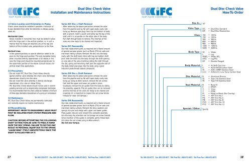
1.0 Valve Location and Orientation in Piping<br />
<strong>Check</strong> valves should be installed if possible a minimum of<br />
6 pipe diameters from other line elements. i.e. elbows, pumps,<br />
valves, etc.<br />
Horizontal Lines<br />
· <strong>Valves</strong> installed in horizontal lines must be bolted in place<br />
with the hinge post in the vertical position. i.e. in such a<br />
manner that the hinge pin retainers are at the top and<br />
bottom of the installed valve, perpendicular to the flow.<br />
Vertical Lines<br />
· In the upward position, no special attention needs to be<br />
given to the hinge post position. The only exception being<br />
when mounted directly downstream of an elbow. In this<br />
case the hinge post should be mounted perpendicular to<br />
the outermost portion of the elbow. Consult factory for<br />
vertical down flow applications.<br />
2.0 Precautions<br />
· Do not install IFC Dual Disc <strong>Check</strong> <strong>Valves</strong> directly<br />
against another valve whereby the check valve discharges<br />
downstream directly into the valve.<br />
· Do not install the valve whereby it directly discharges<br />
downstream into a tee or elbow fitting.<br />
· IFC Dual Disc <strong>Check</strong> <strong>Valves</strong> should not be used in severe<br />
pulsating services such as reciprocating compressor discharges.<br />
· It is recommended that the check valves be installed a minimum<br />
of three pipe diameters downstream of a pump or compressor.<br />
3.0 Maintenance<br />
IFC Dual Disc <strong>Check</strong> <strong>Valves</strong> are permanently lubricated<br />
and normally require no routine maintenance.<br />
4.0 Reconditioning<br />
IMPORTANT! PRIOR TO DISASSEMBLY, VALVE MUST<br />
FIRST BE ISOLATED FROM SYSTEM PRESSURE AND<br />
FLOW.<br />
CAUTION! BEFORE ATTEMPTING THE FOLLOWING<br />
SHAFT EXTRACTION, BE SURE TO PRESS A HAND<br />
OVER THE DISC SPRING. FAILURE TO DO THIS MAY<br />
RESULT IN PERSONAL INJURY DUE TO THE SPRING<br />
“LAUNCHING” ITSELF UNEXPECTEDLY ONCE THE<br />
SHAFT IS PULLED FREE OF IT.<br />
Series DC Disc & Shaft Removal<br />
· After observing the above precaution, remove the valve<br />
from the pipeline and lay flat with open, body cavity side<br />
facing up. Remove pipe plugs from top and bottom of body<br />
with a wrench. Insert a punch and lightly tap the top of the<br />
shaft until it is accessible on the other side of the body.<br />
Pull shaft through body to remove.The internals of the<br />
valve are now ready to be cleaned and inspected.<br />
Series DC Reassembly<br />
Use new replacement parts, as required and a liberal amount<br />
of general-purpose grease (such as Mystic JT-6) on seals and<br />
machined mating surfaces. Reinsert the disc into the body<br />
cavity with the shaft holes inline with top and bottom shaft<br />
port. Slide the shaft into the body through the shaft opening<br />
on one side of the valve. Continue sliding the shaft through<br />
the disc, spring and remaining shaft port the opposite side of<br />
the body. Install pipe plugs into the body using a good<br />
industrial grade thread sealant compound.<br />
Series DR Disc & Shaft Removal<br />
· After observing the above precaution, remove the valve<br />
from the pipeline and lay flat with open, body cavity side<br />
facing up. Using an Allen wrench, remove the set screws<br />
that hold the upper and lower pin guides in place.<br />
Cautiously remove the pin guides from the body by sliding<br />
the assembly upwards. The pin guides then can be removed<br />
and the internals of the valve are ready to be cleaned and<br />
inspected. (It is important to inspect the set screw female<br />
threads for wear and damage.)<br />
Series DR Reassembly<br />
Use new replacement parts, as required and a liberal amount<br />
of general-purpose grease (such as Mystic JT-6) on seals and<br />
machined mating surfaces. Reinsert the discs, washers and<br />
springs into pins and realign with upper and lower guides.<br />
Press guides into pins and reinsert the complete assembly<br />
into the body. Pay attention not to damage set screw threads.<br />
Once insertion of the guides is complete, gently thread back<br />
into place the set screws using an Allen wrench.<br />
Do not over torque.<br />
17 Tel. 905-335-8777 Fax. 905-335-0977 Toll Free Tel. 1-866-872-0072 Toll Free Fax. 1-866-872-0073<br />
Tel. 905-335-8777 Fax. 905-335-0977 Toll Free Tel. 1-866-872-0072 Toll Free Fax. 1-866-872-0073<br />
18