
Create successful ePaper yourself
Turn your PDF publications into a flip-book with our unique Google optimized e-Paper software.
13428 TC IFC Cover 11/10/06 8:44 AM Page 1
13428 TC IFC <strong>Check</strong> 11/10/06 8:46 AM Page 2<br />
Table Of Contents<br />
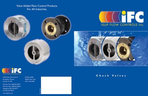
Dual Disc and Silent <strong>Check</strong> <strong>Valves</strong><br />
Dual Disc and Silent <strong>Check</strong> <strong>Valves</strong> 2<br />
Dual Disc <strong>Check</strong> <strong>Valves</strong><br />
Dual Disc <strong>Check</strong> Valve Design Features . . . . . . . . . . . . . . . . . . . . . . . . . . . . . . . . . . . .3<br />
IFC Series DC Cast Iron Dual Disc <strong>Check</strong> <strong>Valves</strong> . . . . . . . . . . . . . . . . . . . . . . . . . . . .5<br />
IFC Series DC Cast Steel Dual Disc <strong>Check</strong> <strong>Valves</strong> . . . . . . . . . . . . . . . . . . . . . . . . . . .7<br />
IFC Series DR Retainerless Dual Disc <strong>Check</strong> <strong>Valves</strong> . . . . . . . . . . . . . . . . . . . . . . . . . .9<br />
Dual Disc <strong>Check</strong> Valve Engineering Data:<br />
Dual Disc Pressure Drop – Liquids . . . . . . . . . . . . . . . . . . . . . . . . . . . . . . . . . . .14<br />
Cv Values (US-GPM @ 1 PSID) . . . . . . . . . . . . . . . . . . . . . . . . . . . . . . . . . . . . . .14<br />
Dual Disc Pressure Drop – Air . . . . . . . . . . . . . . . . . . . . . . . . . . . . . . . . . . . . . .15<br />
Method of Calculating <strong>Flow</strong> . . . . . . . . . . . . . . . . . . . . . . . . . . . . . . . . . . . . . . . . .15<br />
Material Selection Guide . . . . . . . . . . . . . . . . . . . . . . . . . . . . . . . . . . . . . . . . . . .16<br />
Installation and Maintenance Instructions . . . . . . . . . . . . . . . . . . . . . . . . . . . . . . . . .17<br />
How to Order . . . . . . . . . . . . . . . . . . . . . . . . . . . . . . . . . . . . . . . . . . . . . . . . . . . . . . .18<br />
Limited Warranty<br />
All products are warranted to be free of defects in<br />
material and workmanship for a period of one year<br />
from the date of shipment, subject to the limitations<br />
below: If the purchaser believes a product defective,<br />
the purchaser shall: (a) Notify the manufacturer, state<br />
the alleged defect and request permission to return<br />
the product. (b) If permission is given, return the<br />
product with transportation prepaid. If the product is<br />
accepted for return and found to be defective, the<br />
manufacturer will, at its discretion, either repair or<br />
replace the product, f.o.b. factory, within 60 days of<br />
receipt, or refund the purchase price.<br />
Silent <strong>Check</strong> <strong>Valves</strong><br />
Silent <strong>Check</strong> Valve Design Features . . . . . . . . . . . . . . . . . . . . . . . . . . . . . . . . . . . . . .19<br />
IFC Series SC Silent <strong>Check</strong> <strong>Valves</strong> (NPT, SW Ends) . . . . . . . . . . . . . . . . . . . . . . . . . .21<br />
IFC Series SC Cast Iron Wafer Silent <strong>Check</strong> <strong>Valves</strong> . . . . . . . . . . . . . . . . . . . . . . . . . .23<br />
IFC Series SC Cast Iron Flanged Silent <strong>Check</strong> <strong>Valves</strong> . . . . . . . . . . . . . . . . . . . . . . . .25<br />
IFC Series SC Cast Steel Wafer Silent <strong>Check</strong> <strong>Valves</strong> . . . . . . . . . . . . . . . . . . . . . . . . .27<br />
IFC Series SC Cast Steel Flanged Silent <strong>Check</strong> <strong>Valves</strong> . . . . . . . . . . . . . . . . . . . . . . . .29<br />
IFC Series FV Flanged Foot <strong>Valves</strong> . . . . . . . . . . . . . . . . . . . . . . . . . . . . . . . . . . . . . . .31<br />
Silent <strong>Check</strong> Valve Engineering Data:<br />
Silent <strong>Check</strong> Valve Pressure Drop (NPT, SW Ends) . . . . . . . . . . . . . . . . . . . . . .33<br />
Silent Wafer <strong>Check</strong> Valve Pressure Drop . . . . . . . . . . . . . . . . . . . . . . . . . . . . . . .33<br />
Silent Flanged <strong>Check</strong> Valve Pressure Drop . . . . . . . . . . . . . . . . . . . . . . . . . . . . .34<br />
Method of Calculating <strong>Flow</strong> . . . . . . . . . . . . . . . . . . . . . . . . . . . . . . . . . . . . . . . . .34<br />
Installation and Maintenance Instructions . . . . . . . . . . . . . . . . . . . . . . . . . . . . . . . . .35<br />
Installation Requirements . . . . . . . . . . . . . . . . . . . . . . . . . . . . . . . . . . . . . . . . . . . . . .36<br />
Pressure-Temperature Ratings . . . . . . . . . . . . . . . . . . . . . . . . . . . . . . . . . . . . . . . . . .37<br />
How to Order . . . . . . . . . . . . . . . . . . . . . . . . . . . . . . . . . . . . . . . . . . . . . . . . . . . . . . .38<br />
Notes: The material in this catalogue is for general information. For specific performance data and proper<br />
material selection, consult factory or your IFC representative. Although every attempt has been made<br />
to ensure that the information contained in this catalogue is correct IFC Inc. reserves the right to change<br />
designs, materials and/or specifications without notice.<br />
Other than to repair, replace or refund described<br />
above, the purchaser agrees that the manufacturer<br />
shall not be liable for any losses, costs, expenses or<br />
damages of any kind arising out of the product,<br />
its use, installation or replacement, labeling,<br />
instructions, information or technical data of any<br />
kind, description of product use, sample or model,<br />
warnings or lack of foregoing. No other warranties,<br />
written or oral, expressed or implied, including the<br />
warranties of fitness for a particular purpose and<br />
merchantability, are made or authorized.<br />
No affirmation of fact, promise, description of<br />
product use or sample or model shall create any<br />
warranty from the manufacturer, unless signed<br />
by the president. These products are not<br />
manufactured, sold or intended for personal, family<br />
or household purposes.<br />
Applications:<br />
· Process Industry<br />
· Power Industry<br />
· Chemical Industry<br />
· Oil and Gas<br />
· Pulp and Paper<br />
· Metals and Mining<br />
· Water and Waste<br />
Size Range:<br />
· 2”-48” (50mm - 1200mm)<br />
End Connections:<br />
· Threaded (NPT)<br />
· Socket Weld (SW)<br />
· Wafer Flat Face<br />
· Wafer Raised Face<br />
· Wafer RTJ<br />
· Flanged<br />
Available Seat Materials:<br />
· Buna-N<br />
· EPDM<br />
· Viton<br />
· PTFE<br />
· Metal to Metal<br />
Features:<br />
· Compact design.<br />
· Low pressure loss.<br />
· Minimal installation costs.<br />
· Optional Dual Disc retainerless model.<br />
Available Materials of Construction:<br />
· Cast iron body, bronze & stainless steel trim.<br />
· Carbon steel body, stainless steel trim.<br />
· Stainless steel body, stainless steel trim.<br />
· Various exotic alloys.<br />
1 Tel. 905-335-8777 Fax. 905-335-0977 Toll Free Tel. 1-866-872-0072 Toll Free Fax. 1-866-872-0073<br />
Tel. 905-335-8777 Fax. 905-335-0977 Toll Free Tel. 1-866-872-0072 Toll Free Fax. 1-866-872-0073<br />
2
13428 TC IFC <strong>Check</strong> 11/10/06 8:46 AM Page 4<br />
Dual Disc <strong>Check</strong> Valve Design Features<br />
Dual Disc <strong>Check</strong> Valve Design Features<br />
Wafer Dual Disc Design Advantage<br />
The short face to face design inherently makes this check<br />
valve significantly lighter 1 . The valve is designed to fit between<br />
two flanges and requires no flanges of its own. The dual disc<br />
check valve can be installed in any position as the spring aids<br />
in keeping the valve closed 2 . These features allow you to<br />
design your piping layout in the most efficient and least<br />
expensive fashion.<br />
1 10% of the weight of a conventional swing check<br />
2<br />
Consult factory for vertical downward flow<br />
Shock Bumpers<br />
An integral cast bumper (Fig. 1) is present on all IFC Dual<br />
Disc <strong>Check</strong> <strong>Valves</strong> (Except class 125 lb). The bumpers can be<br />
found on both discs, which meet when the valve reaches a<br />
fully open position. This design feature prevents the discs from<br />
pressing against the stop pin and eliminates leverage that<br />
would cause unnecessary stresses and wear. The purpose of<br />
the stop pin is to prevent over-travel of either disc, which<br />
would result in valve failure.<br />
Resilient Seat<br />
The basic design of the IFC Dual Disc <strong>Check</strong> Valve is<br />
illustrated in Fig. 2. This seal is chemically bonded using<br />
specially designed adhesives that provide rubber tearing bonds<br />
throughout the operating range of the seat material. In case of<br />
resilient seat failure, the IFC design permits the discs to float<br />
and make contact with the metal surface the seats were<br />
adhered to. This feature allows the valve to function even if<br />
the resilient seat is not present. IFC also has available a seat<br />
design illustrated in Fig. 3. This design results in a controlled<br />
seat squeeze and provides a metal-to-metal backup seal (Fig.4).<br />
Fig. 2<br />
Retainerless Option<br />
The IFC Series DR Dual Disc <strong>Check</strong> Valve incorporates a retainerless hinge pin design, such that no screwed plugs are required<br />
in the assembly of the valve. This design feature eliminates the potential leak path to atmosphere associated with many<br />
competitors’ designs. The IFC Series DR utilizes Allen set screws to retain two pin guides that house both the hinge and stop<br />
pins. This allows for quick disassembly of the valve without the use of force or special tools other than an Allen wrench.This<br />
unique feature ensures that today’s and the future’s valve fugitive emission requirements are met.<br />
Fig. 3<br />
Fig. 1<br />
Fig. 4<br />
Minimal Seat Wear<br />
The IFC Dual Disc <strong>Check</strong> Valve was designed to eliminate the possibility of seat wear caused by friction at the heel of the dual<br />
discs while maintaining low back pressure sealing capabilities. The clearance between the body, disc and hinge pin results in the<br />
discs cracking open at the heel location first (Fig. 5). When the valve opens the heel does not drag across the seating surface and<br />
cause wear (Fig. 6). As the valve closes, the spring will take the toe of the disc into the seating surface first, while the line back<br />
pressure will force the heels and hinge pin back to the seat to complete the seal (Fig. 7).<br />
Fig. 8<br />
Standards of Construction<br />
Component<br />
Standard<br />
Pressure Boundary Design ASME B16.34<br />
Dimensional Criteria<br />
ASME B16.1, B16.42, B16.47, API-594<br />
Pressure / Temp. Rating ASME B16.1, ASME B16.34<br />
Visual Examination<br />
MSS SP-55<br />
Pressure Testing<br />
API-598<br />
Fig. 5 Fig. 6<br />
Fig. 7<br />
3 Tel. 905-335-8777 Fax. 905-335-0977 Toll Free Tel. 1-866-872-0072 Toll Free Fax. 1-866-872-0073<br />
Tel. 905-335-8777 Fax. 905-335-0977 Toll Free Tel. 1-866-872-0072 Toll Free Fax. 1-866-872-0073<br />
4
13428 TC IFC <strong>Check</strong> 11/10/06 8:46 AM Page 6<br />
IFC Series DC<br />
Cast Iron Dual Disc <strong>Check</strong> <strong>Valves</strong><br />
IFC Series DC<br />
Cast Iron Dual Disc <strong>Check</strong> <strong>Valves</strong><br />
Design Features<br />
· Available in wafer body style. Suitable for installation between FF or RF flanges.<br />
· Valve sizes 6” and larger are complete with a valve lifting lug tap.<br />
· Teflon thrust washers are standard.<br />
· Available with resilient (Buna-N or EPDM) seats.<br />
· Seat design lifts then swings discs to minimize seat wear.<br />
· Body meets ASME B16.1, space API 594.<br />
· Testing is performed in accordance with API 598.<br />
· All valves are equipped with independent springs that optimize the closing rates of<br />
each valve plate, while minimizing spring stress.<br />
1<br />
2<br />
3<br />
5<br />
6<br />
ØA<br />
C<br />
ØD<br />
4<br />
7<br />
8<br />
9<br />
B<br />
E<br />
Parts List and Standard Materials<br />
Part Description Specifications<br />
1 Body A126-B Cast Iron<br />
2 Discs Aluminum Bronze B148<br />
C954 or 316 SS A351-CF8M<br />
3 Seat Buna-N or EPDM<br />
4 Hinge Pin 316 SS<br />
5 Spring 316 SS<br />
6 Thrust Washers Teflon / Phenolic<br />
7 Stop Pin 316 SS<br />
8 Hinge Pin Retainer 1 A126-B<br />
9 Stop Pin Retainer 1 A126-B<br />
Notes: 1. Materials of equivalent strength may be substituted at manufacturer’s option.<br />
2. See page 6 for part identification.<br />
Valve Size<br />
Pressure Temperature Chart (In Accordance with ASME B16.1,A126-B)<br />
Upper Pressure Limits (Non-Shock)<br />
2”-12” (50-300mm) 200 (13.79)<br />
14”- 48” (350-1200mm) 150 (10.34)<br />
Lower Temperature Limits<br />
Body/Seat Material<br />
M.A.W.P psig (Bars)<br />
Lower Limit °F (°C)<br />
A126-B -20° (-28.9°)<br />
Buna-N / EPDM -13° (-25°)<br />
Dimensional Data (Class 125)<br />
Stud Selection<br />
Size 1 ØA B C 2 ØD E Qty. Dia. Length Weight<br />
in. (mm) in. (mm) in. (mm) in. (mm) in. (mm) in. (mm) in. (mm) in. (mm) lb. (kg)<br />
2 (50) 4.13 (105) 2.13 (54) 2.00 (51) 2.38 (60) 0.13 (3) 4 0.63 (16) 5.50 (140) 4 (1.8)<br />
2.5 (65) 4.88 (124) 2.13 (54) 2.50 (64) 2.88 (73) 0.50 (13) 4 0.63 (16) 6.00 (152) 5.5 (2.5)<br />
3 (80) 5.38 (137) 2.25 (57) 3.00 (76) 3.50 (89) 0.63 (16) 4 0.63 (16) 6.25 (159) 7.5 (3.4)<br />
4 (100) 6.88 (175) 2.50 (64) 4.00 (102) 4.50 (114) 1.00 (25) 8 0.63 (16) 6.25 (159) 13.5 (6.1)<br />
5 (125) 7.75 (197) 2.75 (70) 5.00 (127) 5.50 (140) 1.25 (32) 8 0.75 (19) 7 (184) 17.5 (7.9)<br />
6 (150) 8.75 (222) 3.00 (76) 6.00 (152) 6.63 (168) 1.63 (41) 8 0.75 (19) 8.00 (203) 26.5 (12.0)<br />
8 (200) 11.00 (279) 3.75 (95) 8.00 (203) 8.63 (219) 2.38 (60) 8 0.75 (19) 9.50 (241) 50 (22.7)<br />
10 (250) 13.38 (340) 4.25 (108) 10.00 (254) 10.75 (273) 3.00 (76) 12 0.88 (22) 10.50 (267) 70 (31.8)<br />
12 (300) 16.13 (410) 5.63 (143) 12.00 (305) 12.75 (324) 3.88 (99) 12 0.88 (22) 12.25 (311) 110 (49.9)<br />
14 (350) 17.75 (451) 7.25 (184) 12.50 (318) 14.00 (356) 4.00 (102) 12 1.00 (25) 13.00 (330) 170 (77.1)<br />
16 (400) 20.25 (514) 7.50 (191) 15.00 (381) 16.00 (406) 5.25 (133) 16 1.00 (25) 13.50 (343) 225 (102.1)<br />
18 (450) 21.61 (549) 8.00 (203) 17.00 (432) 18.00 (457) 6.00 (152) 16 1.13 (29) 14.50 (368) 280 (127.0)<br />
20 (500) 23.86 (606) 8.38 (213) 19.00 (483) 20.00 (508) 6.88 (175) 20 1.13 (29) 15.25 (387) 390 (176.9)<br />
24 (600) 28.25 (718) 8.75 (222) 22.75 (578) 24.00 (610) 8.25 (210) 20 1.25 (32) 16.25 (413) 590 (267.6)<br />
Notes: 1. Dimensions are in accordance with API 594 except face to face dimensions of 2.5” thru 12” valves.<br />
2. Minimum bore diameter of companion flanges.<br />
3. Larger sizes available upon request.<br />
General: 1. For pressure loss information please see page 14.<br />
2. For ordering information please see page 18.<br />
3. Dimensions are subject to change. Contact factory for certified prints when required.<br />
5 Tel. 905-335-8777 Fax. 905-335-0977 Toll Free Tel. 1-866-872-0072 Toll Free Fax. 1-866-872-0073<br />
Tel. 905-335-8777 Fax. 905-335-0977 Toll Free Tel. 1-866-872-0072 Toll Free Fax. 1-866-872-0073<br />
6
13428 TC IFC <strong>Check</strong> 11/10/06 8:46 AM Page 8<br />
IFC Series DC<br />
Cast Steel Dual Disc <strong>Check</strong> <strong>Valves</strong><br />
IFC Series DC<br />
Cast Steel Dual Disc <strong>Check</strong> <strong>Valves</strong><br />
Design Features<br />
· Available in wafer body style.<br />
· Suitable for installation between RF or RTJ (Optional) flanges.<br />
· Valve sizes 6” and larger are complete with a valve lifting lug.<br />
· Upper and lower stainless steel thrust washers are standard.<br />
· Available with resilient or metal to metal seats.<br />
· Seat design lifts then swings discs to minimize seat wear.<br />
· Discs are equipped with shock bumpers to minimize stresses in hinge pins.<br />
· Body meets ASME B16.34 and API 594.<br />
· Testing is performed in accordance with API 598.<br />
1<br />
2<br />
3<br />
5<br />
6<br />
ØA<br />
C<br />
F<br />
ØD<br />
4<br />
7<br />
8<br />
9<br />
B<br />
E<br />
Parts List and Standard Materials<br />
Part Description Carbon Steel Stainless Steel<br />
1 Body A216-WCB A351-CF8M<br />
2 Discs A351-CF8M A351-CF8M<br />
3 Seat Viton or Viton or<br />
Metal to Metal Metal to Metal<br />
4 Hinge Pin 316 SS 316 SS<br />
5 Spring 316 SS 316 SS<br />
6 Thrust Washers 316 SS 316 SS<br />
7 Stop Pin 316 SS 316 SS<br />
8 Hinge Pin Retainer 1 A105 A182-316<br />
9 Stop Pin Retainer 1 A105 A182-316<br />
Notes: 1. Materials of equivalent strength may be substituted at manufacturer’s option.<br />
2. See page 8 for part identification.<br />
Pressure Temperature Chart (In Accordance with ASME B16.34, CF8M)<br />
Upper Pressure Limits (Non-Shock)<br />
IFC Model Body M.A.W.P.<br />
Material psig (Bars)<br />
DC150 A216-WCB 285 (19.65)<br />
A351-CF8M 275 (18.96)<br />
DC300 A216-WCB 740 (51.02)<br />
A351-CF8M 720 (49.64)<br />
DC600 A216-WCB 1480 (102.04)<br />
A351-CF8M 1440 (99.28)<br />
Lower Temperature Limits<br />
Body/Seat Material<br />
SSI SERIES 600<br />
SSI SERIES 600WT<br />
SSI SERIES 300WT<br />
SSI SERIES 300<br />
SSI SERIES 150<br />
SSI SERIES 150WT<br />
Lower Limit °F (°C)<br />
WCB, CF8M -20° (-28.9°)<br />
Viton -40° (-40°)<br />
Dimensional Data (Class 125)<br />
Size 1 ANSI ØA B C 2 ØD E F 3 Qty. Dia. Length Weight<br />
in. (mm) Rating in. (mm) in. (mm) in. (mm) in. (mm) in. (mm) in. (mm) in. (mm) in. (mm) lb. (Kg.)<br />
2 (50) 150 4.13 (105) 2.38 (60) - 2.38 (60) - 0.63 (16) 4 0.63 (16) 6.00 (152) 6 (2.7)<br />
300 4.38 (111) 2.38 (60) - 2.38 (60) - 0.63 (16) 8 0.63 (16) 6.88 (175) 6 (2.7)<br />
600 4.38 (111) 2.38 (60) - 2.38 (60) - 0.63 (16) 8 0.63 (16) 6.88 (175) 6 (2.7)<br />
3 (80) 150 5.38 (137) 2.88 (73) 2.00 (51) 3.50 (89) 0.25 (6) 0.66 (17) 4 0.63 (16) 7.00 (178) 13 (5.9)<br />
300 5.88 (149) 2.88 (73) 2.00 (51) 3.50 (89) 0.25 (6) 0.66 (17) 8 0.75 (19) 8.13 (207) 13 (5.9)<br />
600 5.88 (149) 2.88 (73) 2.00 (51) 3.50 (89) 0.25 (6) 0.66 (17) 8 0.75 (19) 8.13 (207) 13 (5.9)<br />
4 (100) 150 6.88 (175) 2.88 (73) 3.38 (86) 4.50 (114) 0.75 (19) 0.66 (17) 8 0.63 (16) 7.00 (178) 18 (8.2)<br />
300 7.13 (181) 2.88 (73) 3.38 (86) 4.50 (114) 0.75 (19) 0.66 (17) 8 0.75 (19) 8.13 (207) 18 (8.2)<br />
6 (150) 150 8.75 (222) 3.88 (99) 5.38 (137) 6.63 (168) 1.38 (35) 0.66 (17) 8 0.75 (19) 8.25 (210) 35 (15.9)<br />
300 9.88 (251) 3.88 (99) 5.38 (137) 6.63 (168) 1.38 (35) 0.81 (21) 12 0.75 (19) 9.63 (245) 44 (20.0)<br />
8 (200) 150 11.00 (279) 5.00 (127) 7.38 (187) 8.63 (219) 2.00 (51) 0.69 (18) 8 0.75 (19) 9.75 (248) 63 (28.7)<br />
300 12.13 (308) 5.00 (127) 7.38 (187) 8.63 (219) 2.00 (51) 0.88 (22) 12 0.88 (22) 11.25 (286) 76 (34.6)<br />
10 (250) 150 13.38 (340) 5.75 (146) 9.50 (241) 10.75 (273) 2.88 (73) 0.81 (21) 12 0.88 (22) 11.00 (279) 106 (48.2)<br />
300 14.25 (362) 5.75 (146) 9.50 (241) 10.75 (273) 2.88 (73) 1.00 (25) 16 1.00 (25) 12.75 (324) 126 (57.3)<br />
12 (300) 150 16.13 (410) 7.13 (181) 11.25 (286) 12.75 (324) 3.38 (86) 0.88 (22) 12 0.88 (22) 12.25 (311) 180 (81.8)<br />
300 16.63 (422) 7.13 (181) 11.25 (286) 12.75 (324) 3.38 (86) 1.06 (27) 16 1.13 (29) 14.63 (372) 200 (90.7)<br />
Notes: 1. Valve sizes 2”, 3” and 4” are multi/dual pressure class rated.<br />
2. Minimum bore diameter of companion flanges.<br />
3. Design wall thickness only. Contact factory for actual measurements.<br />
General: 1. For pressure loss information please see page 14.<br />
2. For ordering information please see page 18.<br />
3. Dimensions are subject to change. Contact factory for certified prints when required.<br />
Stud Selection<br />
Notes: 1. Upon prolonged exposure to temperatures above 800°F, the carbide phase of carbon steel may be converted to graphite.<br />
7 Tel. 905-335-8777 Fax. 905-335-0977 Toll Free Tel. 1-866-872-0072 Toll Free Fax. 1-866-872-0073<br />
Tel. 905-335-8777 Fax. 905-335-0977 Toll Free Tel. 1-866-872-0072 Toll Free Fax. 1-866-872-0073<br />
8
13428 TC IFC <strong>Check</strong> 11/10/06 8:46 AM Page 10<br />
IFC Series DR<br />
Retainerless Dual Disc <strong>Check</strong> <strong>Valves</strong><br />
IFC Series DR<br />
Retainerless Dual Disc <strong>Check</strong> <strong>Valves</strong><br />
6<br />
1<br />
2<br />
3<br />
4<br />
9<br />
7<br />
8<br />
5<br />
10<br />
Parts List and Standard Materials<br />
Design Features<br />
· Retainerless design meets industry fugitive emissions control requirements.<br />
This design eliminates the potential leak path to atmosphere associated with<br />
competitors’ valves with threaded retaining plugs.<br />
· Available in wafer, lug and double flanged body styles.<br />
· Suitable for installation between RF or RTJ (Optional) flanges.<br />
· Valve sizes 6” and larger are supplied with a valve lifting lug.<br />
· Upper and lower stainless steel thrust washers are standard.<br />
· Available with resilient or metal-to-metal seats.<br />
· Seat design lifts then swings disc to minimize seat wear.<br />
· Discs are equipped with shock bumpers to minimize stress in hinge pins.<br />
· Body meets ASME B16.34 and API 598.<br />
Part Description Cast Iron Carbon Steel 4 Carbon Steel Carbon Steel Carbon Steel Carbon Steel<br />
API Trim # 1 API Trim # 5 API Trim # 8 API Trim # 10<br />
Resilient Seal Resilient Seal Metal Overlay Seal Metal Overlay Seal Metal Overlay Seal Metal Overlay Seal<br />
1 Body A126-B A216-WCB A216-WCB A216-WCB A216-WCB A352-LCC<br />
A352-LCC<br />
2 Plates 1 A351-CF8M A351-CF8M A217 CA15 A217 CA15 A217 CA15 A351-CF8M<br />
3 Body Seat Buna-N / EPDM Viton 410 SS Stellite 6 Stellite 6 316 SS<br />
4 Plate Seat As Plate As Plate As Plate Stellite 6 As Plate As Plate<br />
5 Guide 316 SS 316 SS 410 SS 410 SS 410 SS 316 SS<br />
6 Hinge Pin 316 SS 316 SS 410 SS 410 SS 410 SS 316 SS<br />
7 Spring 2 316 SS 316 SS Inconel X750 Inconel X750 Inconel X750 Inconel X750<br />
8 Thrust Washers 316 SS 316 SS 410 SS 410 SS 410 SS 316 SS<br />
9 Stop Pin 316 SS 316 SS 410 SS 410 SS 410 SS 410 SS<br />
10 Set Screw 316 SS 316 SS 316 SS 316 SS 316 SS 316 SS<br />
Upper Temperature Limits<br />
Spring Material Upper Limit °F (°C)<br />
316 SS 250° (121°)<br />
Inconel X750 1000° (537°)<br />
Monel 400° (204°)<br />
Hastelloy 800° (426°)<br />
Inconel 625 1000° (537°)<br />
Alloy 20 250° (121°)<br />
Seat Material<br />
Upper Limit °F (°C)<br />
Buna-N 250° (121°)<br />
EPDM 300° (149°)<br />
Viton 400° (204°)<br />
PTFE 450° (232°)<br />
Metal Overlay<br />
As Body<br />
Metal to Metal<br />
As Body<br />
Lower Temperature Limits 1<br />
Material<br />
Lower Limit °F (°C)<br />
A126-B/WCB -20° (-28.9°)<br />
LCC -50° (-45.6°)<br />
CF8M -450° (-268°)<br />
Buna-N -70° (-56.7°)<br />
EPDM -14° (-25.6°)<br />
Viton -40° (-40°)<br />
PTFE -200° (-129°)<br />
Metal<br />
As Body<br />
Upper Pressure Limits (Non-Shock)<br />
IFC Model Body Material MAWP psig (bars)<br />
DR125 A126-B 200 (13.79)<br />
A126-B (>12”) 150 (10.34)<br />
DR150 WCB 285 (19.65)<br />
LCC 290 (19.99)<br />
CF8M 275 (18.96)<br />
DR300 WCB 740 (51.02)<br />
LCC 750 (51.71)<br />
CF8M 720 (51.02)<br />
DR600 WCB 1480 (102.04)<br />
LCC 1500 (103.42)<br />
CF8M 1440 (99.28)<br />
DR900 WCB 2220 (153.06)<br />
LCC 2250 (155.13)<br />
CF8M 2160 (148.93)<br />
DR1500 WCB 3705 (255.45)<br />
LCC 3750 (258.55)<br />
CF8M 3600 (248.21)<br />
DR2500 WCB 6170 (425.41)<br />
LCC 6250 (430.92)<br />
CF8M 6000 (413.69)<br />
Part Description Carbon Steel Stainless Steel Stainless Steel Stainless Steel Stainless Steel Stainless Steel<br />
API Trim # 12 API Trim # 5 API Trim # 10 API Trim # 12<br />
Metal Overlay Seal Resilient Seal Resilient Seal Metal Overlay Seal Metal Overlay Seal Metal Overlay Seal<br />
Pressure Temperature Chart (In Accordance with ASME B16.34, CF8M)<br />
1 Body A352-LCC A351-CF8M A351-CF8M A351-CF8M A351-CF8M A351-CF8M<br />
2 Plates 1 A351-CF8M A351-CF8M A351-CF8M A351-CF8M A351-CF8M A351-CF8M<br />
3 Body Seat Stellite 6 Viton PTFE Stellite 6 As Body Stellite 6<br />
4 Plate Seat As Plate As Plate As Plate Stellite 6 As Plate As Plate<br />
SSI SERIES 600<br />
SSI SERIES 600WT<br />
5 Guide 316 SS 316 SS 316 SS 316 SS 316 SS 316 SS<br />
6 Hinge Pin 316 SS 316 SS 316 SS 316 SS 316 SS 316 SS<br />
SSI SERIES 300WT<br />
SSI SERIES 300<br />
7 Spring 2 Inconel X750 316 SS 316 SS Inconel X750 Inconel X750 Inconel X750<br />
8 Thrust Washers 316 SS 316 SS 316 SS 316 SS 316 SS 316 SS<br />
9 Stop Pin 316 SS 316 SS 316 SS 316 SS 316 SS 316 SS<br />
10 Set Screw 316 SS 316 SS 316 SS 316 SS 316 SS 316 SS<br />
SSI SERIES 150<br />
SSI SERIES 150WT<br />
Notes: 1. If required plates are available in 316 SS (CF8M) instead of 410 SS (CA15).<br />
2. Springs are available in either 316 SS or Inconel X750. Other spring material available upon request.<br />
3. Various body, plate and trim combinations are available. Contact factory for materials not shown.<br />
4. A352-LCC material not to be used above 650°F.<br />
9 Tel. 905-335-8777 Fax. 905-335-0977 Toll Free Tel. 1-866-872-0072 Toll Free Fax. 1-866-872-0073<br />
Notes: 1. Upon prolonged exposure to temperatures above 800°F, the carbide phase of carbon steel may be converted to graphite.<br />
Tel. 905-335-8777 Fax. 905-335-0977 Toll Free Tel. 1-866-872-0072 Toll Free Fax. 1-866-872-0073<br />
10
13428 TC IFC <strong>Check</strong> 11/10/06 8:46 AM Page 12<br />
IFC Series DR Retainerless<br />
Cast Steel Dual Disc <strong>Check</strong> <strong>Valves</strong><br />
IFC Series DR Retainerless<br />
Cast Steel Dual Disc <strong>Check</strong> <strong>Valves</strong><br />
ØA<br />
C<br />
ØD<br />
ØA<br />
C<br />
ØD<br />
Dimensional Data (Class 125-2500)<br />
Size ANSI End A B C 6 D Qty. Dia. Length Weight<br />
in. (mm) Rating Facing in. (mm) in. (mm) in. (mm) in. (mm) in. (mm) in. (mm) lb. (Kg.)<br />
2 (50) 125 FF 4.09 (104) 2.13 (54) - 2.38 (60) 4 0.63 (16) 5.75 (146) 6 (2.7)<br />
150 RF 4.13 (105) 2.38 (60) - 2.38 (60) 4 0.63 (16) 6.00 (152) 7 (3.2)<br />
300 RF/RJ-23 4.38 (111) 2.38 (60) - 2.38 (60) 8 0.63 (16) 6.88 (175) 7 (3.2)<br />
600 RF/RJ-23 4.38 (111) 2.38 (60) - 2.38 (60) 8 0.63 (16) 6.88 (175) 7 (3.2)<br />
900 RF/RJ-24 5.63 (143) 2.75 (70) - 2.25 (57) 8 0.88 (22) 8.75 (222) 18 (8.2)<br />
1500 RF/RJ-24 5.63 (143) 2.75 (70) - 2.25 (57) 8 0.88 (22) 8.75 (222) 18 (8.2)<br />
2500 RF/RJ-26 5.75 (146) 2.75 (70) - 2.25 (57) 8 1.00 (25) 10.00 (254) 29 (13.2)<br />
2.5 (65) 125 FF 4.88 (124) 2.13 (54) - 2.88 (73) 4 0.63 (16) 6.00 (152) 6 (2.7)<br />
150 RF 4.88 (124) 2.38 (60) - 3.00 (76) 4 0.63 (16) 6.38 (162) 11 (5)<br />
3 (80) 125 FF 5.38 (137) 2.25 (57) 2.00 (51) 3.75 (76) 4 0.63 (16) 6.25 (159) 8 (3.6)<br />
150 RF 5.38 (137) 2.88 (73) 2.00 (51) 3.50 (89) 8 0.63 (16) 7.00 (178) 13 (5.9)<br />
300 RF 5.88 (149) 2.88 (73) 2.00 (51) 3.50 (89) 8 0.75 (19) 8.13 (207) 13 (5.9)<br />
600 RF 5.88 (149) 2.88 (73) 2.00 (51) 3.50 (89) 8 0.75 (19) 8.13 (207) 13 (5.9)<br />
900 RF/RJ-31 6.63 (168) 3.25 (83) 2.38 (60) 3.50 (89) 8 0.88 (22) 9.50 (241) 26 (12)<br />
1500 RF/RJ-35 6.88 (175) 3.25 (83) 2.38 (60) 3.50 (89) 8 1.13 (29) 10.50 (267) 28 (12.7)<br />
2500 RF/RJ-32 7.75 (197) 3.38 (86) 2.38 (60) 3.50 (89) 8 1.25 (32) 12.25 (311) 35 (15.9)<br />
4 (100) 125 FF 6.88 (175) 2.50 (64) 3.50 (89) 4.50 (114) 8 0.63 (16) 6.25 (159) 14 (6.4)<br />
150 RF 6.88 (175) 2.88 (73) 3.50 (89) 4.50 (114) 8 0.63 (16) 7.00 (178) 18 (8.2)<br />
300 RF 7.13 (181) 2.88 (73) 3.50 (89) 4.50 (114) 8 0.75 (19) 8.13 (207) 18 (8.2)<br />
600 RF/RJ-37 7.63 (194) 3.13 (80) 3.50 (89) 4.50 (114) 8 0.88 (22) 9.50 (241) 28 (12.8)<br />
900 RF/RJ-37 8.13 (207) 4.00 (102) 3.25 (83) 4.50 (114) 8 1.13 (29) 11.00 (279) 42 (19.1)<br />
1500 RF/RJ-39 8.25 (210) 4.00 (102) 3.25 (83) 4.50 (114) 8 1.25 (32) 12.00 (305) 45 (20.5)<br />
2500 RF/RJ-38 9.25 (235) 4.13 (105) 3.25 (83) 4.50 (114) 8 1.50 (38) 14.63 (371) 64 (29.1)<br />
6 (150) 125 FF 8.75 (222) 3.00 (76) 5.50 (140) 6.63 (168) 8 0.75 (19) 8.00 (203) 27 (12.3)<br />
150 RF 8.75 (222) 3.88 (99) 5.50 (140) 6.63 (168) 8 0.75 (19) 8.25 (210) 35 (15.9)<br />
300 RF 9.88 (251) 3.88 (99) 5.50 (140) 6.63 (168) 12 0.75 (19) 9.63 (245) 44 (20)<br />
600 RF/RJ-45 10.50 (267) 5.38 (137) 3.50 (89) 6.50 (168) 12 1.00 (25) 12.38 (314) 80 (36.4)<br />
900 RF/RJ-45 11.38 (289) 6.25 (159) 3.50 (89) 6.50 (168) 12 1.13 (29) 14.00 (356) 119 (54.1)<br />
1500 RF/RJ-46 11.13 (283) 6.25 (159) 3.50 (89) 6.50 (168) 12 1.38 (35) 16.75 (425) 116 (53)<br />
2500 RF/RJ-47 12.50 (318) 6.25 (159) 3.50 (89) 6.50 (168) 8 2.00 (51) 20.50 (521) 154 (70)<br />
Notes: See Page 13<br />
General: 1. For pressure loss information please see page 14.<br />
2. For ordering information please see page 18.<br />
3. Dimensions are subject to change. Contact factory for certified prints when required.<br />
11 Tel. 905-335-8777 Fax. 905-335-0977 Toll Free Tel. 1-866-872-0072 Toll Free Fax. 1-866-872-0073<br />
B<br />
Stud Selection<br />
(Continued...)<br />
Dimensional Data (Class 125-2500)<br />
Size ANSI End A B C 6 D Qty. Dia. Length Weight<br />
in. (mm) Rating Facing in. (mm) in. (mm) in. (mm) in. (mm) in. (mm) in. (mm) lb. (Kg.)<br />
8 (200) 125 FF 11.00 (279) 3.75 (95) 6.75 (171) 8.63 (219) 8 0.75 (19) 9.50 (241) 50 (22.8)<br />
150 RF 11.00 (279) 5.00 (127) 6.75 (171) 8.63 (219) 8 0.75 (19) 9.75 (248) 63 (28.6)<br />
300 RF 12.13 (308) 5.00 (127) 6.75 (171) 8.63 (219) 12 0.88 (22) 11.25 (286) 76 (34.5)<br />
600 RF/RJ-49 12.63 (321) 6.50 (165) 6.63 (168) 8.13 (207) 12 1.13 (29) 14.50 (368) 160 (72.7)<br />
900 RF/RJ-49 14.13 (359) 8.13 (207) 5.13 (130) 8.13 (207) 12 1.38 (35) 17.13 (435) 271 (123.2)<br />
1500 RF/RJ-50 13.88 (353) 8.13 (207) 5.13 (130) 8.13 (207) 12 1.63 (41) 20.25 (514) 257 (116.8)<br />
2500 RF/RJ-51 15.25 (387) 8.13 (207) 5.63 (143) 8.13 (207) 12 2.00 (51) 24.00 (610) 293 (133.2)<br />
10 (250) 125 FF 13.38 (340) 4.25 (108) 9.25 (235) 10.75 (273) 12 0.88 (22) 10.50 (267) 70 (31.8)<br />
150 RF 13.38 (340) 5.75 (146) 9.25 (235) 10.75 (273) 12 0.88 (22) 11.00 (279) 106 (48.2)<br />
300 RF 14.25 (362) 5.75 (146) 9.25 (235) 10.75 (273) 16 1.00 (25) 12.75 (324) 126 (57.3)<br />
600 RF/RJ-53 15.75 (400) 8.38 (213) 7.88 (200) 10.25 (260) 16 1.25 (32) 17.13 (435) 260 (118.2)<br />
900 RF/RJ-53 17.13 (435) 9.50 (241) 7.69 (195) 10.25 (260) 16 1.38 (35) 19.00 (483) 434 (197.3)<br />
1500 RF/RJ-54 17.13 (435) 9.75 (248) 7.25 (184) 10.25 (260) 12 1.88 (48) 23.50 (597) 449 (204.1)<br />
2500 RF/RJ-55 18.75 (476) 10.00 (254) 7.50 (191) 10.25 (260) 12 2.50 (64) 30.50 (775) 480 (218.2)<br />
12 (300) 125 FF 16.00 (406) 5.63 (143) 10.25 (260) 12.50 (318) 12 0.88 (22) 10.75 (273) 110 (50)<br />
150 RF 16.13 (410) 7.13 (181) 10.25 (260) 12.75 (324) 12 0.88 (22) 12.25 (311) 180 (81.8)<br />
300 RF 16.63 (422) 7.13 (181) 10.25 (260) 12.75 (324) 16 1.13 (29) 14.63 (372) 200 (90.9)<br />
600 RF/RJ-57 18.00 (457) 9.00 (229) 9.13 (232) 11.82 (300) 20 1.25 (32) 18.00 (457) 360 (163.6)<br />
900 RF/RJ-57 19.63 (499) 11.50 (292) 8.13 (207) 11.82 (300) 20 1.38 (35) 21.75 (552) 644 (292.7)<br />
1500 RF/RJ-58 20.50 (521) 12.00 (305) 8.25 (210) 11.82 (300) 16 2.00 (51) 27.50 (699) 824 (374.5)<br />
2500 RF/RJ-60 21.63 (549) 12.00 (305) 8.88 (226) 11.82 (300) 12 2.75 (70) 34.50 (876) 870 (395)<br />
14 (350) 125 FF 17.75 (451) 7.25 (184) 11.25 (286) 14.00 (356) 12 1.00 (25) 13.00 (330) 170 (77.3)<br />
150 RF 17.75 (451) 7.25 (184) 11.25 (286) 13.38 (340) 12 1.00 (25) 13.00 (330) 270 (122.7)<br />
300 RF 19.38 (486) 8.75 (222) 11.25 (286) 13.34 (339) 20 1.13 (29) 16.50 (419) 390 (177.3)<br />
600 RF/RJ-61 19.38 (486) 10.75 (273) 9.13 (232) 13.38 (340) 20 1.38 (35) 20.25 (419) 410 (186.4)<br />
900 RF/RJ-62 20.50 (521) 14.00 (356) - 13.38 (340) 20 1.50 (38) 25.50 (648) 872 (396.4)<br />
1500 RF/RJ-63 22.75 (521) 14.00 (356) - 13.38 (340) 16 2.25 (57) 31.50 (800) 1068 (485.5)<br />
Notes: See Page 13<br />
General: 1. For pressure loss information please see page 14.<br />
2. For ordering information please see page 18.<br />
3. Dimensions are subject to change. Contact factory for certified prints when required.<br />
Stud Selection<br />
Tel. 905-335-8777 Fax. 905-335-0977 Toll Free Tel. 1-866-872-0072 Toll Free Fax. 1-866-872-0073<br />
B<br />
(Continued...)<br />
12
13428 TC IFC <strong>Check</strong> 11/10/06 8:46 AM Page 14<br />
IFC Series DR Retainerless<br />
Cast Steel Dual Disc <strong>Check</strong> <strong>Valves</strong><br />
Dual Disc <strong>Check</strong> Valve<br />
Engineering Data<br />
Dual Disc <strong>Check</strong> Valve Pressure Drop – Liquids (Sizes 2”-30”)<br />
FIGURE 9<br />
ØA<br />
C<br />
ØD<br />
Dimensional Data (Class 125-2500)<br />
Size ANSI End A B C 6 D Qty. Dia. Length Weight<br />
in. (mm) Rating Facing in. (mm) in. (mm) in. (mm) in. (mm) in. (mm) in. (mm) lb. (Kg.)<br />
16 (400) 125 FF 20.25 (514) 7.50 (191) 13.00 (330) 16.63 (422) 16 1.00 (25) 13.50 (343) 225 (102.3)<br />
150 RF 20.25 (514) 7.50 (191) 13.00 (330) 15.25 (387) 16 1.00 (25) 13.50 (343) 295 (134.1)<br />
300 RF 21.25 (540) 9.13 (232) 13.00 (330) 15.25 (387) 20 1.25 (32) 17.38 (441) 458 (208.2)<br />
600 RF/RJ-65 22.25 (565) 12.00 (305) 13.00 (330) 15.25 (387) 20 1.50 (38) 22.25 (565) 728 (330.9)<br />
900 RF/RJ-66 22.63 (575) 15.13 (384) 6.38 (162) 15.25 (387) 20 1.63 (38) 27.13 (689) 1174 (533.6)<br />
1500 RF/RJ-67 25.25 (641) 15.13 (384) 6.38 (162) 15.25 (387) 16 2.50 (64) 34.25 (870) 1295 (588.6)<br />
18 (450) 125 FF 21.61 (549) 8.00 (203) 15.50 (394) 18.00 (457) 16 1.13 (29) 14.50 (368) 280 (127.3)<br />
150 RF 21.63 (549.5) 8.00 (203) 15.50 (394) 17.25 (438) 16 1.13 (29) 14.50 (368) 312 (141.8)<br />
B<br />
Stud Selection<br />
300 RF 23.50 (597) 10.38 (264) 15.38 (391) 17.25 (438) 24 1.25 (32) 18.88 (480) 650 (295.5)<br />
600 RF/RJ-69 24.13 (613) 14.25 (362) 13.00 (330) 17.25 (438) 20 1.63 (41) 25.25 (641) 870 (395.5)<br />
900 RF/RJ-70 25.13 (638) 17.75 (451) 9.63 (245) 17.25 (438) 20 1.88 (48) 34.50 (876) 1344 (610.9)<br />
1500 RF/RJ-71 27.75 (705) 18.44 (468) 7.25 (184) 17.25 (438) 16 2.75 (70) 39.75 (1010) 1745 (793.2)<br />
20 (450) 125 FF 23.86 (606) 8.38 (213) 17.25 (438) 20.16 (512) 20 1.13 (29) 15.25 (387) 390 (177.3)<br />
150 RF 23.88 (607) 8.63 (219) 17.25 (438) 19.19 (487) 20 1.13 (29) 15.13 (384) 472 (214.5)<br />
300 RF 25.75 (654) 11.50 (292) 17.25 (438) 19.19 (487) 24 1.25 (32) 20.50 (521) 801 (364.1)<br />
600 RF/RJ-73 26.88 (683) 14.50 (368) 17.00 (432) 19.19 (487) 24 1.63 (41) 26.25 (667) 1196 (543.6)<br />
900 RF/RJ-74 27.50 (699) 17.75 (451) 16.00 (406) 19.19 (487) 20 2.00 (51) 32.50 (826) 1406 (639.1)<br />
1500 RF/RJ-75 29.75 (756) 21.00 (533) 8.25 (210) 19.19 (487) 16 3.00 (76) 44.25 (1124) 2812 (1278.2)<br />
24 (600) 125 FF 28.25 (718) 8.75 (222) 21.13 (537) 23.75 (603) 20 1.25 (32) 16.25 (413) 590 (268.2)<br />
150 RF 28.25 (718) 8.75 (222) 21.13 (537) 22.75 (578) 20 1.25 (32) 16.25 (413) 788 (358.2)<br />
300 RF 30.50 (775) 12.50 (318) 20.63 (524) 22.75 (578) 24 1.50 (38) 22.75 (578) 1150 (526.4)<br />
600 RF/RJ-77 31.13 (791) 17.25 (438) 20.63 (524) 22.75 (578) 24 1.88 (48) 30.75 (781) 1802 (819.1)<br />
900 RF/RJ-78 33.00 (838) 19.50 (495) 17.50 (445) 22.75 (578) 20 2.50 (64) 38.00 (965) 2713 (1233.2)<br />
1500 RF/RJ-79 35.50 (902) 22.00 (559) 15.38 (391) 22.75 (578) 16 3.50 (89) 48.50 (1232) 5968 (2712.7)<br />
30 (750) 125 FF 34.75 (883) 12.00 (305) 25.25 (641) 30.00 (762) 28 1.25 (32) 21.00 (533) 1450 (659.1)<br />
150 RF 34.75 (883) 12.00 (305) 25.25 (641) 28.93 (735) 28 1.25 (32) 21.00 (533) 1456 (661.8)<br />
36 (750) 125 FF 41.25 (1048) 14.50 (368) 25.50 (648) 36.00 (914) 32 1.50 (38) 25.88 (657) 1505 (684.1)<br />
150 RF 41.25 (1048) 14.50 (368) 25.50 (648) 34.00 (864) 32 1.50 (38) 25.88 (657) 1505 (684.1)<br />
Notes: 1. Dimensions are in accordance with API 594 except face to face dimension of 2.5” through 12” cast iron body (A126-B) valves.<br />
2. Valve sizes 2” and 3” Class 150, 300 and 600 lb. are multi/dual pressure class rated.<br />
3. Valve sizes 4” Class 150 and 300 lb. are multi/dual pressure class rated.<br />
4. <strong>Valves</strong> sizes through 24” are designed for installation between flanges in dimensional accordance with ASME B16.1 and ASME B16.5.<br />
5. <strong>Valves</strong> sizes 30” and larger are designed for installation between flanges in dimensional accordance with ASME B16.47 Series A.<br />
6. Minimum Bore Diameter of companion flanges.<br />
General: 1. For pressure loss information please see page 14.<br />
2. For ordering information please see page 18.<br />
3. Dimensions are subject to change. Contact factory for certified prints when required.<br />
13 Tel. 905-335-8777 Fax. 905-335-0977 Toll Free Tel. 1-866-872-0072 Toll Free Fax. 1-866-872-0073<br />
Notes: 1. Pressure drop curves are based on water flow.<br />
2. Valve cracking pressure is equal to or less then 0.3 psid.<br />
3. Valve cracking pressure increases to between 0.75 and 1.25 psid when installed vertically with flow upwards.<br />
Cv Values (US-GPM @ 1 PSID)<br />
Valve Size - in (mm) Cv Valve Size - in (mm) Cv<br />
2” (50mm) 48 12” (300mm) 4295<br />
3” (75mm) 171 14” (350mm) 5463<br />
4” (100mm) 291 16” (400mm) 7355<br />
5” (125mm) 494 18” (450mm) 9537<br />
6” (150mm) 705 20” (500mm) 12004<br />
8” (200mm) 1795 24” (600mm) 17804<br />
10” (250mm) 2563 30” (750mm) 28660<br />
Tel. 905-335-8777 Fax. 905-335-0977 Toll Free Tel. 1-866-872-0072 Toll Free Fax. 1-866-872-0073<br />
14
13428 TC IFC <strong>Check</strong> 11/10/06 8:46 AM Page 16<br />
Dual Disc <strong>Check</strong> Valve Pressure Drop–Air @ 60°F, 1 ATM (Sizes 2”- 30”)<br />
Notes: 1. Pressure drop curves are based on air flow at 60°F and 1 ATM pressure.<br />
2. Valve cracking pressure is equal to or less then 0.3 psid.<br />
3. Valve cracking pressure increases to between 0.75 and 1.25 psid when installed vertically with flow upwards.<br />
Method of Calculating <strong>Flow</strong><br />
Liquid <strong>Flow</strong><br />
Cv = Q<br />
Saturated Vapour<br />
Cv =<br />
W<br />
K<br />
G<br />
∆P<br />
1<br />
∆P (P 1<br />
+ P 2<br />
)<br />
Q = Cv<br />
∆P<br />
G<br />
Variables<br />
Cv = Valve Coefficient<br />
∆P = (P 1 - P 2 ) Pressure Drop<br />
P 1 = Inlet Pressure (PSIA)<br />
P 2 = Outlet Pressure (PSIA)<br />
G = Specific Gravity<br />
Water = 1.0 at 60°F and 1 ATM<br />
Air = 1.0 at 60°F and 1 ATM<br />
∆P = G<br />
( ) 2<br />
Q<br />
Cv<br />
Gas <strong>Flow</strong><br />
Cv =<br />
Q<br />
963<br />
GT<br />
∆P (P 1<br />
+ P 2<br />
)<br />
Superheated Vapour<br />
Q = 963Cv<br />
Dual Disc <strong>Check</strong> Valve<br />
Engineering Data<br />
∆P (P 1<br />
+ P 2<br />
)<br />
GT<br />
W = CvK ∆P (P + P ) W(1+0.0007T SH ) 1<br />
Cv =<br />
CvK<br />
1 2 K ∆P (P 1<br />
+ P 2<br />
) Cv =<br />
(1+0.0007T SH )<br />
∆P (P + P ) 1 2<br />
FIGURE 10<br />
Q = <strong>Flow</strong><br />
Liquid = USGPM<br />
Gas = SCFH<br />
T = Absolute Temperature (°F + 460)<br />
T SH = Superheat (°F)<br />
Total Temperature Minus Saturation Temperature<br />
W = lbs. Per Hour (LB/H)<br />
K = Constant For Vapours<br />
15 Tel. 905-335-8777 Fax. 905-335-0977 Toll Free Tel. 1-866-872-0072 Toll Free Fax. 1-866-872-0073<br />
A - Recommended, B - May Be Acceptable (Testing Recommended), N - Not Recommended<br />
CORROSIVE MEDIA BODY / DISC MATERIALS SEAT MATERIALS<br />
AB CS 316 EPDM BUNA-N VITON<br />
Acetaldehyde A B A A N N<br />
Acetone A A A B N N<br />
Acetylene N A A A A<br />
Air A A A A A A<br />
Aluminum Acetate A A A A B N<br />
Aluminum Nitrate N N A A A A<br />
Amino Acids N A N N A<br />
Ammonia Gas A A B 70° N<br />
Ammonium Bicarbonate B A A N N<br />
Ammonium Phosphate N A A A A<br />
Arsenic Acid N N A A A A<br />
Beer-Breweries N N A A A A<br />
Beet Sugar Liquors A N A A A A<br />
Benzene A A A N N 70°<br />
Brine B N A A A A<br />
Bromine - Anhydrous N N N N N A<br />
Bromine - Wet N N N N N A<br />
Butane A A A N A A<br />
Butanoic Acid<br />
A<br />
Butyl Alcohol A A A B A A<br />
Butylene (Gas) A A A N N A<br />
Calcium Chlorate N A A A A A<br />
Calcium Hydroxide B B A A A A<br />
Carbonated Water N B A A A A<br />
Carbon Monoxide A A A A A B<br />
Carbonic Acid N B A A A A<br />
Caster Oil A A A B A A<br />
Chlorine (Wet or Dry) N 70° N N N A<br />
Cider B N A A B A<br />
Citric Acid B N A A A A<br />
Citrus Juices B N A A A A<br />
Corn Oil A A A N A A<br />
Diacetone Alcohol A A A A N N<br />
Dibutyl Phthalate A A B N N<br />
Dichloroethane A N N A<br />
Diesel Fuel A A A N A A<br />
Diethylamine N A A N B A<br />
Diphenyl Oxide B A A N N A<br />
Dowtherm A A A N N A<br />
Ethanol A A A A A N<br />
Ether A A A N N N<br />
Ethyl Acetate B A A B N N<br />
Ethyl Chloride B 200° A A A A<br />
Ethylene Glycol A A A A A A<br />
Ethylene Oxide N A A N N N<br />
Fatty Acids N N A N A A<br />
Ferrous Chloride N N N A A A<br />
Fish Oils B B A A<br />
Gas-Natural A A A N A A<br />
Gasoline - Ethyl A A A N N A<br />
Gasoline - Regular A A A N A A<br />
Glucose A A A A A A<br />
Glycerine A A A A A A<br />
Helium Gas A A A A A A<br />
Hydraulic Fluid (Pydraul) A A A N N A<br />
Hydrocarbons (Aromatic) N A A N N A<br />
Hydrogen Peroxide N N A A N A<br />
Hydrogen Sulfide N B A A 70° N<br />
Iodine N N N N N A<br />
Isopropyl Acetate B B N N<br />
Kerosene A A A N A A<br />
Notes: 1. If # appears material is recommended for use up to indicated temperature (°F).<br />
2. AB = Aluminum Bronze, CS = Carbon Steel, 316 = 316 Stainless Steel.<br />
3. If uncertain please contact factory concerning valve compatibility.<br />
Tel. 905-335-8777 Fax. 905-335-0977 Toll Free Tel. 1-866-872-0072 Toll Free Fax. 1-866-872-0073<br />
Dual Disc <strong>Check</strong> Valve<br />
Engineering Data<br />
Material Selection Guide<br />
CORROSIVE MEDIA BODY / DISC MATERIALS SEAT MATERIALS<br />
AB CS 316 EPDM BUNA-N VITON<br />
Lactic Acid N A 70° 70° A<br />
Lime A A A B A<br />
Liquefied Petroleum Gas A A A N A A<br />
Mercuric Chloride B N B A A A<br />
Mercury N A A A A A<br />
Methane A A A N A A<br />
Methyl Alcohol A A A A B N<br />
Methyl Acetate B A B N N<br />
Methyl Chloride A A A N N A<br />
Naphtha A A A N N A<br />
Natural Gas A A A N A A<br />
Nitrogen - Gas A A A A A A<br />
Nitrous Oxide B B A B<br />
Oil - Crude (sweet) A A A N A A<br />
Oil - Crude (sour) A A A N B A<br />
Oil - Vegetable B N A B A A<br />
Oleic Acid B A N N B<br />
Olive Oil B B A B A A<br />
Oxalic Acid A A B A<br />
Oxygen - Gas A A A A B A<br />
Palm Oil N A A A<br />
Paint - Thinner/Remover A A A N N A<br />
Phenol B B A B N A<br />
Plating Solutions N A N A N A<br />
Potassium Acetate N A A B N<br />
Potassium Bisulfate<br />
A<br />
Potassium Chlorate N A A B A<br />
Potassium Cyanide A A A A A A<br />
Potassium Sulfide N A A B N A<br />
Potassium Sulfate A A A A A A<br />
Propylene Glycol N A A A A<br />
Propylene Oxide N A A B<br />
Pyridene B A A B N N<br />
Shellac B A A A A<br />
Silver Nitrate N N A A N A<br />
Sodium Bicarbonate A A A A A A<br />
Sodium Carbonate N B A A A A<br />
Sodium Chlorate N A A B A<br />
Sodium Chloride N B B A A A<br />
Sodium Nitrite B A A A A<br />
Sodium Sulfate A B A A A A<br />
Sodium Sulfide B A A A A A<br />
Sodium Thiosulfate B A A B A<br />
Soybean Oil B B A N A A<br />
Steam and Hot Water A B A A N<br />
Sulfur N B A A N N<br />
Sulfuric Acid N N B N N A<br />
Sulfurous Acid N N B N N A<br />
Tartaric Acid B A B A A<br />
Tetrachloroethane B 75° A N N A<br />
Turpentine A A A N A A<br />
Varnish A A A N N A<br />
Vinegar N N A A B A<br />
Water, Carbonated N B A A A A<br />
Water, Chilled A B A A A A<br />
Water, Distilled N B A A A A<br />
Water, Salt, Sea A N A A A B<br />
Wine B N A A A A<br />
Zinc Bromide N A A<br />
Zinc Cyanide N N A A<br />
Zinc Sulfate N N A A A A<br />
No representation, warranty or guarantee of compatibility, expressed or<br />
implied, is made by this Selection Guide due to the complexity and almost<br />
infinite variations of mixtures, concentrations, temperatures and flow<br />
conditions possible in actual service. As a result, the end user must assume<br />
all responsibility for ultimate determination of value compatibility.<br />
16
13428 TC IFC <strong>Check</strong> 11/10/06 8:46 AM Page 18<br />
Dual Disc <strong>Check</strong> Valve<br />
Installation and Maintenance Instructions<br />
Dual Disc <strong>Check</strong> Valve<br />
How To Order<br />
1.0 Valve Location and Orientation in Piping<br />
<strong>Check</strong> valves should be installed if possible a minimum of<br />
6 pipe diameters from other line elements. i.e. elbows, pumps,<br />
valves, etc.<br />
Horizontal Lines<br />
· <strong>Valves</strong> installed in horizontal lines must be bolted in place<br />
with the hinge post in the vertical position. i.e. in such a<br />
manner that the hinge pin retainers are at the top and<br />
bottom of the installed valve, perpendicular to the flow.<br />
Vertical Lines<br />
· In the upward position, no special attention needs to be<br />
given to the hinge post position. The only exception being<br />
when mounted directly downstream of an elbow. In this<br />
case the hinge post should be mounted perpendicular to<br />
the outermost portion of the elbow. Consult factory for<br />
vertical down flow applications.<br />
2.0 Precautions<br />
· Do not install IFC Dual Disc <strong>Check</strong> <strong>Valves</strong> directly<br />
against another valve whereby the check valve discharges<br />
downstream directly into the valve.<br />
· Do not install the valve whereby it directly discharges<br />
downstream into a tee or elbow fitting.<br />
· IFC Dual Disc <strong>Check</strong> <strong>Valves</strong> should not be used in severe<br />
pulsating services such as reciprocating compressor discharges.<br />
· It is recommended that the check valves be installed a minimum<br />
of three pipe diameters downstream of a pump or compressor.<br />
3.0 Maintenance<br />
IFC Dual Disc <strong>Check</strong> <strong>Valves</strong> are permanently lubricated<br />
and normally require no routine maintenance.<br />
4.0 Reconditioning<br />
IMPORTANT! PRIOR TO DISASSEMBLY, VALVE MUST<br />
FIRST BE ISOLATED FROM SYSTEM PRESSURE AND<br />
FLOW.<br />
CAUTION! BEFORE ATTEMPTING THE FOLLOWING<br />
SHAFT EXTRACTION, BE SURE TO PRESS A HAND<br />
OVER THE DISC SPRING. FAILURE TO DO THIS MAY<br />
RESULT IN PERSONAL INJURY DUE TO THE SPRING<br />
“LAUNCHING” ITSELF UNEXPECTEDLY ONCE THE<br />
SHAFT IS PULLED FREE OF IT.<br />
Series DC Disc & Shaft Removal<br />
· After observing the above precaution, remove the valve<br />
from the pipeline and lay flat with open, body cavity side<br />
facing up. Remove pipe plugs from top and bottom of body<br />
with a wrench. Insert a punch and lightly tap the top of the<br />
shaft until it is accessible on the other side of the body.<br />
Pull shaft through body to remove.The internals of the<br />
valve are now ready to be cleaned and inspected.<br />
Series DC Reassembly<br />
Use new replacement parts, as required and a liberal amount<br />
of general-purpose grease (such as Mystic JT-6) on seals and<br />
machined mating surfaces. Reinsert the disc into the body<br />
cavity with the shaft holes inline with top and bottom shaft<br />
port. Slide the shaft into the body through the shaft opening<br />
on one side of the valve. Continue sliding the shaft through<br />
the disc, spring and remaining shaft port the opposite side of<br />
the body. Install pipe plugs into the body using a good<br />
industrial grade thread sealant compound.<br />
Series DR Disc & Shaft Removal<br />
· After observing the above precaution, remove the valve<br />
from the pipeline and lay flat with open, body cavity side<br />
facing up. Using an Allen wrench, remove the set screws<br />
that hold the upper and lower pin guides in place.<br />
Cautiously remove the pin guides from the body by sliding<br />
the assembly upwards. The pin guides then can be removed<br />
and the internals of the valve are ready to be cleaned and<br />
inspected. (It is important to inspect the set screw female<br />
threads for wear and damage.)<br />
Series DR Reassembly<br />
Use new replacement parts, as required and a liberal amount<br />
of general-purpose grease (such as Mystic JT-6) on seals and<br />
machined mating surfaces. Reinsert the discs, washers and<br />
springs into pins and realign with upper and lower guides.<br />
Press guides into pins and reinsert the complete assembly<br />
into the body. Pay attention not to damage set screw threads.<br />
Once insertion of the guides is complete, gently thread back<br />
into place the set screws using an Allen wrench.<br />
Do not over torque.<br />
17 Tel. 905-335-8777 Fax. 905-335-0977 Toll Free Tel. 1-866-872-0072 Toll Free Fax. 1-866-872-0073<br />
Tel. 905-335-8777 Fax. 905-335-0977 Toll Free Tel. 1-866-872-0072 Toll Free Fax. 1-866-872-0073<br />
18
13428 TC IFC <strong>Check</strong> 11/10/06 8:46 AM Page 20<br />
Silent <strong>Check</strong> Valve<br />
Design Features<br />
Silent <strong>Check</strong> Valve<br />
Design Features<br />
Why Use a Silent <strong>Check</strong> Valve?<br />
Water hammer is the generation and<br />
effect of high pressure shock waves<br />
(transients) in relatively incompressible<br />
fluids. When a liquid is decelerated<br />
abruptly in a pipe by a valve disc, water<br />
hammer is caused by the resulting shock<br />
waves. These high pressure waves act<br />
against the piping and the valve, exerting<br />
very high forces that can result in large<br />
stress on the metal and vibrations in the<br />
system. If not accounted for, these high<br />
transient forces can damage the pipe or<br />
other components in the system.<br />
The problems of water hammer can<br />
be eliminated or greatly minimized by<br />
installing an IFC Silent <strong>Check</strong> Valve.<br />
Unlike a swing check valve, IFC Series<br />
Silent <strong>Check</strong> <strong>Valves</strong> do not rely on<br />
gravity or reverse flow to successfully<br />
close and seat. Instead, as the forward<br />
moving fluid slows, a spring assists the<br />
valve in closing.<br />
Due to the relative short distance the<br />
disc must travel when compared to<br />
other types of check valves, the valve<br />
closes prior to the fluid forward velocity<br />
reaching zero.<br />
When reverse flow is eliminated, the<br />
forces necessary to produce water<br />
hammer are substantially minimized.<br />
Conventional Swing <strong>Check</strong><br />
Silent <strong>Check</strong><br />
CHART 1<br />
Pressure<br />
Spikes<br />
Elapsed Time<br />
It is known that the magnitude of these surge pressures is proportional to the velocity change that occurs and the properties of<br />
the fluid and pipe (namely the compressibility of the fluid and the expandability of the pipe). The magnitude of the pressure rise<br />
can be modeled as:<br />
Where: PR = Pressure Rise<br />
a = Speed of Sound<br />
VR max = Maximum Reverse Velocity of the fluid which is a function<br />
of the system deceleration and check valve type.<br />
= Density<br />
Therefore, different valves will produce different pressure surge magnitudes. Chart 2 outlines the relative effectiveness of various<br />
types of check valves in handling fluid deceleration.<br />
A<br />
<strong>Valves</strong> are equipped with<br />
double guided stems and<br />
large bearing surfaces to<br />
minimize wear and ensure<br />
proper disc seating. (SC600T<br />
valves are single guided only)<br />
B<br />
Standard metal to metal<br />
seating and optional<br />
resilient seating results in<br />
a check valve that is<br />
suitable for various liquid,<br />
gas or steam applications.<br />
C<br />
The spring-assisted design insures<br />
that as forward flow decreases, the<br />
disc begins to move towards the<br />
seat. By the time the flow stops,<br />
the disc is closed thus minimizing<br />
the effects of water hammer.<br />
CHART 2<br />
D E F G<br />
Seat Retainer DOES NOT<br />
rely on gasket compression<br />
to remain in place, thus<br />
eliminating possible line<br />
gasket blow-out. (Series<br />
SC150 and SC300 only)<br />
<strong>Valves</strong> designed to<br />
open at 0.5 psid<br />
differential pressure and<br />
fully open at 1.0 psid<br />
differential pressure.<br />
With most sizes, valves’<br />
disc lift meets or exceeds<br />
1 /4 ” for each inch of<br />
nominal pipe size, thus<br />
minimizing the valve<br />
pressure drop in the full<br />
open condition.<br />
The concave discs<br />
minimize side thrust<br />
that can result in<br />
premature valve failure.<br />
19 Tel. 905-335-8777 Fax. 905-335-0977 Toll Free Tel. 1-866-872-0072 Toll Free Fax. 1-866-872-0073<br />
Tel. 905-335-8777 Fax. 905-335-0977 Toll Free Tel. 1-866-872-0072 Toll Free Fax. 1-866-872-0073<br />
20
13428 TC IFC <strong>Check</strong> 11/10/06 8:46 AM Page 22<br />
IFC Series SC Stainless Steel Threaded<br />
and Socket Weld Silent <strong>Check</strong> <strong>Valves</strong><br />
IFC Series SC Stainless Steel Threaded<br />
and Socket Weld Silent <strong>Check</strong> <strong>Valves</strong><br />
Design Features<br />
· <strong>Valves</strong> are available with threaded (N.P.T.), socket weld or butt-weld<br />
inlet/outlet connections.<br />
· Three-piece body style for ease of maintenance.<br />
· 316 SS construction with Teflon “O” ring body seals.<br />
· Spring assisted silent closing.<br />
· Standard metal to metal seating.<br />
· Threaded and socket weld connections meet the requirements of table 4<br />
of ASME B16.34<br />
· Testing is performed in accordance with ASME B16.34<br />
C<br />
D<br />
B<br />
A1, A2<br />
Parts List and Standard Materials<br />
Part Description Specifications<br />
1 Body A351-CF8M 316 Stainless Steel<br />
2 Cap A351-CF8M 316 Stainless Steel<br />
3 Plug A351-CF8M 316 Stainless Steel<br />
4 Spring 1 Type 316 SS<br />
5 Holder A351-CF8M 316 Stainless Steel<br />
6 Gasket PTFE<br />
7 Assembly Hardware 300 Series Stainless Steel<br />
Notes: 1. Materials of equivalent strength may be substituted at manufacturer’s option.<br />
Pressure Temperature Chart<br />
Upper Pressure Limits (Non-Shock)<br />
Valve Size - in. (mm) M.A.W.P. - psig (Bars)<br />
1 /4 ”-4” (8-200mm) 600 (41.36)<br />
Upper Temperature Limits<br />
Gasket Material Upper Limit °F (°C)<br />
PTFE 400° (204°)<br />
Lower Temperature Limits<br />
Body<br />
Lower Limit °F (°C)<br />
A351-CF8M -20° (-28.9°)<br />
Dimensional Data (Class 125)<br />
Size A1 1 A2 1 B C D 2 Weight Cv<br />
in. (mm) in. (mm) in. (mm) in. (mm) in. (mm) in. (mm) lb. (Kg.)<br />
1 /4 (8) 2.09 (53) 2.50 (64) 0.56 (14) 0.50 (13) 0.555 (14.10) 1 (0.5) 3<br />
3 /8 (10) 2.09 (53) 2.50 (64) 0.56 (14) 0.50 (13) 0.690 (17.53) 1 (0.5) 5<br />
1 /2 (15) 2.63 (67) 2.63 (67) 0.69 (18) 0.59 (15) 0.855 (21.72) 1 (0.5) 7<br />
3 /4 (20) 2.63 (67) 3.13 (80) 0.88 (22) 0.75 (19) 1.065 (27.05) 3 (1.4) 13<br />
1 (25) 3.12 (79) 3.50 (89) 1.09 (28) 1.00 (25) 1.330 (33.78) 3.5 (1.6) 22<br />
1 1 / 4 (32) 3.62 (92) 3.63 (92) 1.25 (32) 1.25 (32) 1.675 (42.55) 4 (1.8) 39<br />
1 1 / 2 (40) 3.98 (101) 4.19 (106) 1.46 (37) 1.59 (40) 1.915 (48.64) 5 (2.3) 54<br />
2 (50) 4.50 (114) 4.93 (125) 1.88 (48) 2.00 (51) 2.406 (61.11) 5.5 (2.5) 93<br />
2 1 / 2 (65) 5.75 (146) 5.88 (149) 1.88 (48) 2.50 (64) 2.906 (73.81) 6 (2.7) 123<br />
3 (80) 6.06 (154) 6.63 (168) 2.19 (56) 3.13 (80) 3.535 (89.79) 7 (3.2) 180<br />
4 (100) 7.09 (180) 8.25 (210) 2.75 (70) 4.00 (102) 4.545 (115.44) 12 (5.4) 323<br />
Notes: 1. Dimension A1 refers to NPT and socket weld valves, Dimension A2 refers to Buttweld <strong>Valves</strong>.<br />
2. Dimension D refers to socket weld valves only.<br />
General: 1. For pressure loss information please see page 33.<br />
2. For ordering information please see page 38.<br />
3. Dimensions are subject to change. Contact factory for certified prints when required.<br />
21 Tel. 905-335-8777 Fax. 905-335-0977 Toll Free Tel. 1-866-872-0072 Toll Free Fax. 1-866-872-0073<br />
Tel. 905-335-8777 Fax. 905-335-0977 Toll Free Tel. 1-866-872-0072 Toll Free Fax. 1-866-872-0073<br />
22
13428 TC IFC <strong>Check</strong> 11/10/06 8:46 AM Page 24<br />
IFC Series SC<br />
Cast Iron Silent Wafer <strong>Check</strong> <strong>Valves</strong><br />
IFC Series SC<br />
Cast Iron Silent Wafer <strong>Check</strong> <strong>Valves</strong><br />
Design Features<br />
· Available in wafer body style. Suitable for installation between FF flanges only.<br />
· May be installed between ANSI Class 125/250 and 150/300 flanges.<br />
(Sizes 8” and smaller only)<br />
· Available with aluminum bronze or 316 SS trim.<br />
· Standard metal to metal seating. Optional resilient seats.<br />
· Body meets ASME B16.1<br />
· Testing is performed in accordance with API 598.<br />
C<br />
D<br />
ANSI CLASS<br />
250lb. BOLT<br />
CIRCLE<br />
ANSI CLASS<br />
125lb. BOLT<br />
CIRCLE<br />
B<br />
A<br />
Parts List and Standard Materials<br />
Part Description Specifications<br />
1 Body A126-B Cast Iron<br />
2 Plug B148 C954 Aluminum Bronze<br />
A351-CF8M 316 SS<br />
3 Seat 2 B148 C954 Aluminum Bronze<br />
A351-CF8M 316 SS<br />
4 Spring 1 Type 316 SS<br />
5 Bushing 1 B148 C954 Aluminum Bronze<br />
A351-CF8M 316 SS<br />
6 Set Screw 300 Series Stainless Steel<br />
Notes: 1. Materials of equivalent strength may be substituted at manufacturer’s option.<br />
2. Resilient seats are available. Contact factory.<br />
Temperature (°F)<br />
406<br />
350<br />
300<br />
250<br />
200<br />
Sizes Sizes 8” 8” 8” - - - 12” 12” 12”<br />
Sizes 2” 2” - 6” 6” 6”<br />
Upper Pressure Limits (Non-Shock)<br />
Valve Size - in. (mm)<br />
2”-6” (50 - 150mm) 400 (27.58)<br />
8”- 12” (200 - 300mm) 200 (13.79)<br />
Lower Temperature Limits<br />
Body/Seat Material<br />
Pressure Temperature Chart (In Accordance with ASME B16.1, ASME B16.4, A126-B)<br />
M.A.W.P. - psig (Bars)<br />
Lower Limit °F (°C)<br />
A126-B -20° (-28.9°)<br />
Buna-N, EPDM,Viton -13° (-25°)<br />
Dimensional Data (Class 125/250)<br />
Stud Selection<br />
Size 1 A B C 2 D Qty. Qty. Dia. 125lb. Dia. 250lb. Length Weight Cv<br />
in. (mm) in. (mm) in. (mm) in. (mm) in. (mm) 125lb. 250lb. in. (mm) in. (mm) in. (mm) lb. (kg)<br />
2 (50) 2.63 (67) 4.25 (108) 2.00 (51) 2.38 (60) 4 8 0.63 (16) 0.63 (16) 6.00 (152) 5 (2.3) 57<br />
2.5 (65) 2.88 (73) 5.00 (127) 2.75 (70) 2.88 (60) 4 8 0.63 (16) 0.75 (19) 6.75 (171) 8 (3.6) 87<br />
3 (80) 3.13 (80) 5.75 (146) 3.25 (83) 3.50 (89) 4 8 0.63 (16) 0.75 (19) 7.25 (184) 10 (4.5) 127<br />
4 (100) 4.00 (102) 7.00 (178) 4.00 (102) 4.50 (114) 8 8 0.63 (16) 0.75 (19) 7.75 (197) 17 (7.7) 228<br />
5 (125) 4.75 (121) 8.38 (213) 5.00 (127) 5.50 (140) 8 8 0.75 (19) 0.75 (19) 9.00 (229) 27 (12.3) 357<br />
6 (150) 5.50 (140) 9.75 (248) 6.25 (159) 6.63 (168) 8 12 0.75 (19) 0.75 (19) 10.50 (267) 40 (18.2) 432<br />
8 (200) 6.50 (165) 12.00 (305) 8.38 (213) 8.63 (219) 8 12 0.75 (19) 0.88 (22) 12.25 (311) 90 (40.9) 768<br />
10 (250) 8.25 (210) 16.00 (406) 10.00 (254) 10.38 (264) 12 - 0.88 (22) - 14.50 (368) 160 (72.6) 1240<br />
12 (300) 11.25 (286) 19.00 (483) 11.75 (298) 12.50 (318) 24 - 0.88 (22) - 6.50 (165) 340 (154.4) 1740<br />
Notes: 1. 12” valves are supplied in lug body style.<br />
2. Sizes 2” thru 8” can be installed between both ANSI Class 125lb. and ANSI Class 250lb. flanges.<br />
3. Sizes 10” and larger can only be installed between ANSI Class 125lb. flanges.<br />
4. Full face gaskets are recommended for installation.<br />
5. Soft seats are available. Please consult factory.<br />
General: 1. For pressure loss information please see page 33.<br />
2. For ordering information please see page 38.<br />
3. Dimensions are subject to change. Contact factory for certified prints when required.<br />
150<br />
0 50 100 150 200 250 300 350 400 450 500<br />
Notes: 1. Cast Iron <strong>Valves</strong> are recommended for liquid service only.<br />
Pressure (Psig)<br />
23 Tel. 905-335-8777 Fax. 905-335-0977 Toll Free Tel. 1-866-872-0072 Toll Free Fax. 1-866-872-0073<br />
Tel. 905-335-8777 Fax. 905-335-0977 Toll Free Tel. 1-866-872-0072 Toll Free Fax. 1-866-872-0073<br />
24
13428 TC IFC <strong>Check</strong> 11/10/06 8:46 AM Page 26<br />
IFC Series SC<br />
Cast Iron Silent Flanged <strong>Check</strong> <strong>Valves</strong><br />
IFC Series SC<br />
Cast Iron Silent Flanged <strong>Check</strong> <strong>Valves</strong><br />
6 4 2 3 1 5<br />
Design Features<br />
· Available in flanged body style. Suitable for installation between FF flanges only.<br />
· Available with aluminum bronze or 316 SS trim.<br />
· Standard metal to metal seating. Optional resilient seats.<br />
· Body meets ASME B16.1<br />
· Testing is performed in accordance with API 598.<br />
C<br />
D<br />
B<br />
A<br />
Parts List and Standard Materials<br />
Part Description Specifications<br />
1 Body A126-B Cast Iron<br />
2 Plug B148 C954 Aluminum Bronze<br />
A351-CF8M 316 SS<br />
3 Seat 2 B148 C954 Aluminum Bronze<br />
A351-CF8M 316 SS<br />
4 Spring 1 Type 316 SS<br />
5 Bushing 1 B148 C954 Aluminum Bronze<br />
A351-CF8M 316 SS<br />
6 Set Screw 300 Series Stainless Steel<br />
Notes: 1. Materials of equivalent strength may be substituted at manufacturer’s option.<br />
2. Resilient seats are available. Contact factory.<br />
Pressure Temperature Chart (In Accordance with ASME B16.1, A126-B)<br />
450<br />
Upper Pressure Limits (Non-Shock)<br />
Valve Size - in. (mm)<br />
2”-12” (50 - 300mm) 200 (13.79)<br />
14” - 16” (350 - 400mm) 150 (10.34)<br />
Lower Temperature Limits<br />
Body/Seat Material<br />
M.A.W.P. - psig (Bars)<br />
Lower Limit °F (°C)<br />
A126-B -20° (-28.9°)<br />
Buna-N, EPDM,Viton -13° (-25°)<br />
Dimensional Data (Class 125)<br />
Stud Selection<br />
Size A B C D Qty. Dia. 125lb. Length Weight Cv<br />
in. (mm) in. (mm) in. (mm) in. (mm) in. (mm) 125lb. in. (mm) in. (mm) lb. (kg)<br />
2 (50) 6.25 (159) 4.75 (121) 2.25 (57) 2.00 (51) 4 0.63 (16) 3.25 (83) 16 (7.3) 69<br />
2.5 (65) 7.00 (178) 5.50 (140) 2.63 (67) 2.50 (64) 4 0.63 (16) 3.50 (89) 24 (10.9) 108<br />
3 (80) 7.50 (191) 6.38 (162) 3.38 (86) 3.00 (76) 4 0.63 (16) 3.75 (95) 32 (14.5) 155<br />
4 (100) 8.50 (216) 9.00 (229) 4.38 (111) 4.00 (102) 8 0.63 (16) 3.75 (95) 59 (26.8) 277<br />
5 (125) 9.50 (241) 10.00 (254) 5.25 (133) 5.00 (127) 8 0.75 (16) 4.00 (102) 75 (34.1) 433<br />
6 (150) 10.50 (267) 11.00 (279) 6.25 (159) 6.00 (152) 8 0.75 (16) 4.00 (102) 96 (43.6) 623<br />
8 (200) 13.50 (343) 15.50 (394) 8.38 (213) 8.00 (203) 8 0.75 (16) 4.25 (108) 178 (80.8) 1109<br />
10 (250) 16.25 (413) 18.00 (457) 10.00 (254) 10.00 (254) 12 0.88 (22) 4.75 (121) 280 (127.1) 1733<br />
12 (300) 20.25 (514) 21.00 (533) 12.00 (305) 12.00 (305) 12 0.88 (22) 4.75 (121) 450 (204.3) 2495<br />
14 (350) 22.75 (578) 25.00 (635) 13.25 (337) 13.75 (337) 12 1.00 (25) 5.25 (133) 568 (257.9) 3397<br />
16 (400) 24.75 (629) 26.00 (660) 15.25 (387) 15.75 (400) 16 1.00 (25) 5.50 (140) 840 (381.4) 4437<br />
Temperature (°F)<br />
400<br />
350<br />
300<br />
250<br />
200<br />
Sizes Sizes >12” >12” >12”<br />
Sizes Sizes ≤12” ≤12” 12”<br />
Notes: 1. In most cases, valve sizes 2” thru 10” will mate up to wafer style butterfly valves without the use of spool pieces or other adapters.<br />
2. <strong>Valves</strong> can be installed between ANSI Class 125lb. flanges.<br />
3. Full face gaskets are recommended for installation.<br />
4. Soft seats are available. Please consult factory.<br />
General: 1. For pressure loss information please see page 33.<br />
2. For ordering information please see page 38.<br />
3. Dimensions are subject to change. Contact factory for certified prints when required.<br />
150<br />
0 25 50 75 100 125 150 175 200<br />
Notes: 1. Cast Iron <strong>Valves</strong> are recommended for liquid service only.<br />
Pressure (Psig)<br />
25 Tel. 905-335-8777 Fax. 905-335-0977 Toll Free Tel. 1-866-872-0072 Toll Free Fax. 1-866-872-0073<br />
Tel. 905-335-8777 Fax. 905-335-0977 Toll Free Tel. 1-866-872-0072 Toll Free Fax. 1-866-872-0073<br />
26
13428 TC IFC <strong>Check</strong> 11/10/06 8:46 AM Page 28<br />
IFC Series SC<br />
Cast Steel Silent Wafer <strong>Check</strong> <strong>Valves</strong><br />
IFC Series SC<br />
Cast Steel Silent Wafer <strong>Check</strong> <strong>Valves</strong><br />
Design Features<br />
· Available in wafer body style. Suitable for installation between RF flanges.<br />
· May be installed between ANSI Class 150/300 flanges (Sizes 6” and smaller only).<br />
· Standard metal to metal seating. Optional resilient seats.<br />
· Body meets ASME B16.5 and ASME B16.34.<br />
· Testing is performed in accordance with API 598.<br />
C<br />
D<br />
ANSI CLASS<br />
300lb. BOLT<br />
CIRCLE<br />
Parts List and Standard Materials<br />
Part Description Carbon Steel Stainless Steel<br />
1 Body A216-WCB A351-CF8M 316 SS<br />
2 Plug A351-CF8M 316 SS A351-CF8M 316 SS<br />
3 Seat 2 A351-CF8M 316 SS A351-CF8M 316 SS<br />
4 Spring 1 Type 316 SS Type 316 SS<br />
5 Bushing 1 Type 316 SS Type 316 SS<br />
6 Seat Seal Buna-N Buna-N<br />
Notes: 1. Materials of equivalent strength may be substituted at manufacturer’s option.<br />
2. Resilient seats are available. Contact factory.<br />
Upper Pressure Limits (Non-Shock)<br />
Valve Size - in. (mm) Body Material M.A.W.P. - psig (Bars)<br />
2” - 4” (50 -100mm) A216-WCB 740 (51.02)<br />
A351-CF8M 720 (49.64)<br />
6” - 12” (150 - 250mm) A216-WCB 285 (19.65)<br />
A351-CF8M 275 (18.96)<br />
Pressure Temperature Chart (In Accordance with ASME B16.34, A126-WCB)<br />
Lower Temperature Limits<br />
Body/Seat Material<br />
Lower Limit °F (°C)<br />
A126-WCB,A351-CF8M -20° (-28.9°)<br />
Buna-N, EPDM,Viton -13° (-25°)<br />
Dimensional Data (Class 125)<br />
A<br />
ANSI CLASS<br />
150lb. BOLT<br />
CIRCLE<br />
Stud Selection<br />
Size A B C D Qty. Qty. Dia. 150lb. Dia. 300lb. Length Weight Cv<br />
in. (mm) in. (mm) in. (mm) in. (mm) in. (mm) 150lb. 300lb. in. (mm) in. (mm) in. (mm) lb. (kg)<br />
2 (50) 2.63 (67) 4.25 (108) 2.00 (51) 2.38 (60) 4 8 0.63 (16) 0.63 (16) 6.00 (152) 5 (2.3) 57<br />
2.5 (65) 2.88 (73) 5.00 (127) 2.75 (70) 2.88 (60) 4 8 0.63 (16) 0.75 (19) 6.75 (171) 8 (3.6) 87<br />
3 (80) 3.13 (80) 5.75 (146) 3.25 (83) 3.50 (89) 4 8 0.63 (16) 0.75 (19) 7.25 (184) 10 (4.5) 127<br />
4 (100) 4.00 (102) 7.00 (178) 4.00 (102) 4.50 (114) 8 8 0.63 (16) 0.75 (19) 7.75 (197) 17 (7.7) 228<br />
5 (125) 4.63 (118) 8.38 (213) 5.00 (127) 5.50 (140) 8 8 0.75 (19) 0.75 (19) 9.00 (229) 27 (12.3) 357<br />
6 (150) 5.50 (140) 9.75 (248) 6.25 (159) 6.63 (168) 8 12 0.75 (19) 0.75 (19) 10.50 (267) 40 (18.2) 432<br />
8 (200) 6.50 (165) 12.00 (305) 8.38 (213) 8.63 (219) 8 - 0.75 (19) - 12.25 (311) 90 (40.9) 768<br />
10 (250) 8.25 (210) 16.00 (406) 10.00 (254) 10.38 (264) 12 - 0.88 (22) - 14.50 (368) 160 (72.6) 1240<br />
12 (300) 11.25 (286) 19.00 (483) 11.75 (298) 12.50 (318) 24 - 0.88 (22) - 6.50 (165) 340 (154.4) 1740<br />
Notes: 1. Sizes 2” thru 6” can be installed between both ANSI Class 150lb. and ANSI Class 300lb. flanges.<br />
2. Sizes 8” and larger can only be installed between ANSI Class 150lb. flanges.<br />
3. Soft seats are available. Please consult factory.<br />
4. All sizes have Buna-N (-13°F to 250°F) body O-Ring Seals. Contact factory for other materials.<br />
General: 1. For pressure loss information please see page 33.<br />
2. For ordering information please see page 38.<br />
3. Dimensions are subject to change. Contact factory for certified prints when required.<br />
B<br />
Notes: 1. Maximum operating temperature limited by seat seal material.<br />
2. <strong>Valves</strong> recommended for liquid service only.<br />
27 Tel. 905-335-8777 Fax. 905-335-0977 Toll Free Tel. 1-866-872-0072 Toll Free Fax. 1-866-872-0073<br />
Tel. 905-335-8777 Fax. 905-335-0977 Toll Free Tel. 1-866-872-0072 Toll Free Fax. 1-866-872-0073<br />
28
13428 TC IFC <strong>Check</strong> 11/10/06 8:46 AM Page 30<br />
IFC Series SC<br />
Cast Steel Silent Flanged <strong>Check</strong> <strong>Valves</strong><br />
IFC Series SC<br />
Cast Steel Silent Flanged <strong>Check</strong> <strong>Valves</strong><br />
6 4 2 3 1 5<br />
Design Features<br />
· Available in flanged body style. Suitable for installation between RF flanges.<br />
· Standard metal to metal seating. Optional resilient seats.<br />
· Body meets ASME B16.5 and ASME B16.34.<br />
· Testing is performed in accordance with API 598.<br />
C<br />
D<br />
B<br />
Upper Pressure Limits (Non-Shock)<br />
Valve Size - in. (mm) Body Material M.A.W.P. - psig (Bars)<br />
2” - 12” (50 - 300mm) A216-WCB 285 (19.65)<br />
A351-CF8M 275 (18.96)<br />
A<br />
Parts List and Standard Materials<br />
Part Description Carbon Steel Stainless Steel<br />
1 Body A216-WCB A351-CF8M 316 SS<br />
2 Plug A351-CF8M 316 SS A351-CF8M 316 SS<br />
3 Spring 1 Type 316 SS Type 316 SS<br />
4 Seat 2 A351-CF8M 316 SS A351-CF8M 316 SS<br />
5 Bushing 1 Type 316 SS Type 316 SS<br />
6 Seat Seal Buna-N Buna-N<br />
Notes: 1. Materials of equivalent strength may be substituted at manufacturer’s option.<br />
2. Resilient seats are available. Contact factory.<br />
Pressure Temperature Chart (In Accordance with ASME B16.34, A216-WCB)<br />
Temperature (°F)<br />
400 1<br />
300<br />
250<br />
200<br />
Max Temp. Viton<br />
Max Temp. Buna-N<br />
Lower Temperature Limits<br />
Body/Seat Material<br />
Lower Limit °F (°C)<br />
A216-WCB, A351-CF8M -20° (-28.9°)<br />
Buna-N, EPDM,Viton -13° (-25°)<br />
Dimensional Data (Class 150)<br />
Stud Selection<br />
Size A B C D Qty. Dia. 150lb. Length Weight Cv<br />
in. (mm) in. (mm) in. (mm) in. (mm) in. (mm) 150lb. in. (mm) in. (mm) lb. (kg)<br />
2 (50) 6.25 (159) 4.75 (121) 2.25 (57) 2.00 (51) 4 0.63 (16) 3.25 (83) 16 (7.3) 69<br />
2.5 (65) 7.00 (178) 5.50 (140) 2.63 (67) 2.50 (64) 4 0.63 (16) 3.50 (89) 24 (10.9) 108<br />
3 (80) 7.50 (191) 6.38 (162) 3.38 (86) 3.00 (76) 4 0.63 (16) 3.75 (95) 32 (14.5) 155<br />
4 (100) 8.50 (216) 9.00 (229) 4.38 (111) 4.00 (102) 8 0.63 (16) 3.75 (95) 59 (26.8) 277<br />
5 (125) 9.50 (241) 10.00 (254) 5.25 (133) 5.00 (127) 8 0.75 (16) 4.00 (102) 75 (34.1) 433<br />
6 (150) 10.50 (267) 11.00 (279) 6.25 (159) 6.00 (152) 8 0.75 (16) 4.00 (102) 96 (43.6) 623<br />
8 (200) 13.50 (343) 15.50 (394) 8.38 (213) 8.00 (203) 8 0.75 (16) 4.25 (108) 178 (80.8) 1109<br />
10 (250) 16.25 (413) 18.00 (457) 10.00 (254) 10.00 (254) 12 0.88 (22) 4.75 (121) 280 (127.1) 1733<br />
12 (300) 20.25 (514) 21.00 (533) 12.00 (305) 12.00 (305) 12 0.88 (22) 4.75 (121) 450 (204.3) 2495<br />
Notes: 1. Valved sizes 2” thru 10” will mate up to wafer style butterfly valves without the use of spool pieces or other adapters.<br />
2. <strong>Valves</strong> can be installed between ANSI Class 150lb. flanges.<br />
3. Soft seats are available. Please consult factory.<br />
4. All sizes have Buna-N (-13°F to 250°F) body O-Ring Seals. Contact factory for other materials.<br />
General: 1. For pressure loss information please see page 33.<br />
2. For ordering information please see page 38.<br />
3. Dimensions are subject to change. Contact factory for certified prints when required<br />
100<br />
0 100 200 300 400<br />
Notes: 1. Maximum operating temperature limited by seat seal material.<br />
2. <strong>Valves</strong> recommended for liquid service only.<br />
Pressure (Psig)<br />
29 Tel. 905-335-8777 Fax. 905-335-0977 Toll Free Tel. 1-866-872-0072 Toll Free Fax. 1-866-872-0073<br />
Tel. 905-335-8777 Fax. 905-335-0977 Toll Free Tel. 1-866-872-0072 Toll Free Fax. 1-866-872-0073<br />
30
13428 TC IFC <strong>Check</strong> 11/10/06 8:46 AM Page 32<br />
IFC Series FV Cast Iron, Steel<br />
& Stainless Steel Flanged Foot <strong>Valves</strong><br />
IFC Series FV Cast Iron, Steel<br />
& Stainless Steel Flanged Foot <strong>Valves</strong><br />
5<br />
1<br />
2<br />
3<br />
4<br />
10<br />
6<br />
Design Features<br />
· Available in flanged body style.<br />
· IFC Series FV125 are complete with FF flanges in accordance with ASME B16.1<br />
· IFC Series FV150 are complete with RF flanges in accordance with ASME B16.5<br />
· Standard Screen has 1 / 8 ” dia. holes on 3 / 16 ” centers.<br />
· Standard “Dove Tail” resilient seating.<br />
· Body meets applicable ASME Standard.<br />
7<br />
11<br />
8<br />
9<br />
INLET<br />
Upper Pressure Limits (Non-Shock)<br />
Valve Size - in. (mm) Body Material M.A.W.P. - psig (Bars)<br />
2” - 12” (50 - 300mm) A126-B 200 (13.79)<br />
A216-WCB 285 (19.65)<br />
A351-CF8M 275 (18.96)<br />
Lower Temperature Limits<br />
Body/Seat Material Lower Limit °F (°C)<br />
A216-WCB,A351-CF8M -20° (-28.9°)<br />
Buna-N, EPDM,Viton -13° (-25°)<br />
Parts List and Standard Materials<br />
Part Description Cast Iron Carbon Steel Stainless Steel<br />
1 Body A126-B Cast Iron A216-WCB A351-CF8M 316 SS<br />
2 Plug B148 C954 Aluminum Bronze A351-CF8M 316 SS A351-CF8M 316 SS<br />
A351-CF8M 316 SS<br />
3 Seal 1 Buna-N Buna-N Viton<br />
4 Seat B148 C954 Aluminum Bronze A351-CF8M 316 SS A351-CF8M 316 SS<br />
A351-CF8M 316 SS<br />
5 Bushing B148 C954 Aluminum Bronze A351-CF8M 316 SS A351-CF8M 316 SS<br />
A351-CF8M 316 SS<br />
6 Set Screw 300 Series SS N/A N/A<br />
7 Screen Retainer 300 Series SS 300 Series SS 300 Series SS<br />
8 Ring Plate A105 Carbon Steel A105 Carbon Steel A182 Stainless Steel<br />
9 Screen 304 SS 304 SS 304 SS<br />
10 Bolting A193-B7/A194-2H A193-B7/A194-2H A193-88-1/A194-8<br />
Carbon Steel Carbon Steel Carbon Steel<br />
11 Gasket Rubber Rubber Viton<br />
Notes: 1. Materials of equivalent strength may be substituted at manufacturer’s option.<br />
Dimensional Data (Class 125, 150)<br />
Size A B C D E Open Area Open Area Qty/Flange Dia. Length Weight Cv<br />
in. (mm) in. (mm) in. (mm) in. (mm) in. (mm) in. (mm) in 2 . (mm 2 ) Ratio % 125lb./150lb. in. (mm) in. (mm) lb. (kg)<br />
2 (50) 10.75 (273) 4.75 (121) 2.00 (51) 6.00 (152) 4.38 (111) 38.68 (982) 1231% 4 0.63 (16) 3.25 (83) 23 (10.4) 61<br />
2.5 (65) 11.63 (295) 5.50 (140) 2.50 (64) 7.00 (178) 4.50 (114) 47.32 (1202) 964% 4 0.63 (16) 3.50 (89) 34 (15.4) 94<br />
3 (80) 11.63 (295) 6.38 (162) 3.00 (76) 7.50 (191) 4.00 (102) 45.95 (1167) 650% 4 0.63 (16) 3.75 (95) 43 (19.5) 140<br />
4 (100) 12.63 (321) 9.00 (229) 4.00 (102) 9.00 (229) 4.00 (102) 59.38 (1508) 473% 8 0.63 (16) 3.75 (95) 66 (30.0) 246<br />
5 (125) 14.63 (372) 10.00 (254) 5.00 (127) 10.00 (254) 5.00 (127) 81.68 (2075) 416% 8 0.75 (19) 4.00 (102) 95 (43.1) 388<br />
6 (150) 16.63 (422) 11.00 (279) 6.00 (152) 11.00 (279) 6.00 (152) 107.13 (2721) 379% 8 0.75 (19) 4.00 (102) 120 (54.5) 556<br />
8 (200) 20.75 (527) 15.50 (394) 8.00 (203) 13.50 (343) 7.13 (181) 159.04 (4040) 316% 8 0.75 (19) 4.25 (108) 215 (97.6) 989<br />
10 (250) 25.38 (645) 18.00 (457) 10.00 (254) 16.00 (406) 9.00 (229) 236.25 (6001) 300% 12 0.88 (22) 4.75 (121) 335 (152.1) 1561<br />
12 (300) 31.13 (791) 21.00 (533) 12.00 (305) 19.00 (483) 10.75 (273) 340.23 (8642) 300% 12 0.88 (22) 4.75 (121) 526 (238.8) 2241<br />
14 (350) 36.50 (927) 25.00 (635) 13.75 (349) 21.00 (533) 13.63 (346) 461.81 (11730) 300% 12 1.00 (25) 5.25 (133) 675 (306.5) 3034<br />
16 (400) 41.00 (1041) 26.00 (660) 15.75 (400) 23.50 (597) 16.13 (410) 605.53 (15381) 300% 12 1.00 (25) 5.50 (140) 960 (435.8) 3891<br />
Notes: 1. Screen open area based on a screen constructed from perforated plate with 1/8” dia. holes on 3/16” centers. (40% Open Area Media)<br />
2. Cast Iron valves can be installed between ANSI Class 125lb. flanges.<br />
3. Cast Steel and Stainless Steel valves can be installed between ANSI Class 150lb. flanges.<br />
4. It is recommended that Cast Iron valves have full face gaskets for installation.<br />
General: 1. For pressure loss information please see page 33.<br />
2. For ordering information please see page 38.<br />
3. Dimensions are subject to change. Contact factory for certified prints when required<br />
Stud Selection<br />
31 Tel. 905-335-8777 Fax. 905-335-0977 Toll Free Tel. 1-866-872-0072 Toll Free Fax. 1-866-872-0073<br />
Tel. 905-335-8777 Fax. 905-335-0977 Toll Free Tel. 1-866-872-0072 Toll Free Fax. 1-866-872-0073<br />
32
13428 TC IFC <strong>Check</strong> 11/10/06 8:46 AM Page 34<br />
Silent <strong>Check</strong> Valve<br />
Engineering Data<br />
Silent <strong>Check</strong> Valve<br />
Engineering Data<br />
Series SC600 <strong>Check</strong> Valve Pressure Drop – Liquid (Sizes 1 / 4 ” - 4”)<br />
Flanged Silent <strong>Check</strong> Valve Pressure Drop – Liquids (Sizes 2” - 16”)<br />
FIGURE 11<br />
FIGURE 13<br />
1 10 100 1000<br />
<strong>Flow</strong> Rate (GPM)<br />
Wafer Silent <strong>Check</strong> Valve Pressure Drop – Liquids (Sizes 2” - 12”)<br />
Notes: 1. Pressure drop curves are based on water flow.<br />
2. Valve cracking pressure is equal to or less then 0.5 psid.<br />
3. Valve cracking pressure increases to between 0.75 and 1.25 psid when installed vertically with flow upwards.<br />
FIGURE 12<br />
Method of Calculating <strong>Flow</strong><br />
Liquid <strong>Flow</strong><br />
Cv = Q<br />
G<br />
∆P<br />
Q = Cv<br />
∆P<br />
G<br />
∆P = G<br />
( ) 2<br />
Q<br />
Cv<br />
Gas <strong>Flow</strong><br />
Cv =<br />
Q<br />
963<br />
GT<br />
∆P (P 1<br />
+ P 2<br />
)<br />
Q = 963Cv<br />
∆P (P 1<br />
+ P 2<br />
)<br />
GT<br />
Saturated Vapour<br />
Cv =<br />
W<br />
K<br />
1<br />
∆P (P 1<br />
+ P 2<br />
)<br />
Superheated Vapour<br />
W = CvK ∆P (P + P ) W(1+0.0007T SH ) 1<br />
Cv =<br />
CvK<br />
1 2 K ∆P (P 1<br />
+ P 2<br />
) Cv =<br />
(1+0.0007T SH )<br />
∆P (P + P ) 1 2<br />
Variables<br />
Cv = Valve Coefficient<br />
∆P = (P 1 - P 2 ) Pressure Drop<br />
P 1 = Inlet Pressure (PSIA)<br />
P 2 = Outlet Pressure (PSIA)<br />
G = Specific Gravity<br />
Water = 1.0 at 60°F and 1 ATM<br />
Air = 1.0 at 60°F and 1 ATM<br />
Q = <strong>Flow</strong><br />
Liquid = USGPM<br />
Gas = SCFH<br />
T = Absolute Temperature (°F + 460)<br />
T SH = Superheat (°F)<br />
Total Temperature Minus Saturation Temperature<br />
W = lbs. Per Hour (LB/H)<br />
K = Constant For Vapours<br />
<strong>Flow</strong> Rate (GPM)<br />
33 Tel. 905-335-8777 Fax. 905-335-0977 Toll Free Tel. 1-866-872-0072 Toll Free Fax. 1-866-872-0073<br />
Tel. 905-335-8777 Fax. 905-335-0977 Toll Free Tel. 1-866-872-0072 Toll Free Fax. 1-866-872-0073<br />
34
13428 TC IFC <strong>Check</strong> 11/10/06 8:46 AM Page 36<br />
Silent <strong>Check</strong> Valve<br />
Installation and Maintenance Instructions<br />
Silent <strong>Check</strong> Valve<br />
Installation Requirements<br />
1.0 Valve Location and Orientation in Piping<br />
The IFC Silent <strong>Check</strong> Valve is designed to open fully to allow<br />
forward flow and close rapidly prior to flow reversal.<br />
These valves are used to prevent reverse flow through<br />
pumps or in piping systems. IFC Silent <strong>Check</strong> <strong>Valves</strong> are not<br />
intended for use with fluids containing suspended solids such<br />
as wastewater, or any type of hazardous gas. <strong>Check</strong> valves<br />
should be installed a minimum of 3 pipe diameters from<br />
other line elements. i.e. elbows, pumps, valves, etc.<br />
When the valve is to be reassembled, carefully place the disc<br />
and seat in the valve body to prevent damage to lapped or<br />
soft seat. Reinstall the valve in the line using new flange<br />
gaskets, and replace and torque the bolts using the crossover<br />
flange bolt tightening the method.<br />
CAUTION: The valve seating should never be<br />
inspected by only removing the valve inlet flange<br />
piping, because seat damage or injury could occur.<br />
Installation Requirements<br />
For cast iron valves, damage to the valve and/or internal<br />
leakage may result if pipe flanges other than those with<br />
standard flat faces, conforming to ASME B16.1 or ASME B16.5<br />
are used.<br />
VALVE SEAT<br />
Warning: Flanges having an expanded inside diameter (often found on mortar<br />
lined pipe) cannot be used on the inlet side of the valve. A ring flange having a<br />
maximum inside diameter, as shown in “A” dimension below, must be inserted<br />
between the valve and mortar lined pipe flange.<br />
<strong>Valves</strong> may be installed vertically, horizontally, or at other<br />
angles. Install the valve with proper positioning of the flow<br />
arrow. Support and align piping and valve. Install lubricated<br />
flange bolts and torque using the cross-over flange bolt<br />
tightening method.<br />
Cast iron valves must be mounted to ANSI flat faced cast<br />
iron or steel flanges, while carbon and stainless steel valves<br />
may be mounted between either flat faced or raised face<br />
flanges (Note:The use of raised face flanges against cast iron<br />
valves may cause external leakage and/or damage to the<br />
valve). Gaskets may be full faced or ring type. It is very<br />
important to center the valve to the pipe inner diameter to<br />
prevent internal leakage.<br />
2.0 Maintenance<br />
IFC Series SC <strong>Check</strong> <strong>Valves</strong> normally require no routine<br />
maintenance.<br />
3.0 Reconditioning<br />
IMPORTANT! PRIOR TO DISASSEMBLY, VALVE MUST<br />
FIRST BE ISOLATED FROM SYSTEM PRESSURE AND<br />
FLOW.<br />
When removing the valve from the pipeline, loosen the<br />
outlet flange bolting first, then loosen the inlet flange bolting<br />
CAUTION: Protect eyes and other body parts from<br />
any residual line pressure that may exist in the<br />
pipeline.<br />
The valve may then be removed from the pipeline and<br />
inspected for wear. For cast iron valves the valve seat ring is<br />
removed by removing the seat retaining screws. The seat ring<br />
on steel and stainless steel valves are removed by<br />
unthreading the seat ring in the counterclockwise direction.<br />
After the seat ring is removed, remove the disc, which will<br />
expose the guide bushing and valve spring.The parts that are<br />
worn should be replaced. NOTE: For valves supplied with<br />
soft seats, carefully inspect the O-Ring condition and dovetail<br />
machined groove for damage.<br />
4.0 Troubleshooting<br />
Presented below are several possible valve installation<br />
problems along with possible solutions:<br />
· Valve chatters or vibrates:Verify that the velocity is at least<br />
4 ft/sec. A “clunking” noise may be the result of line<br />
cavitations due to high velocities, low downstream pressure,<br />
or an upstream expander. It is preferred that 3 pipe<br />
diameters of straight pipe are located upstream of the valve.<br />
· Valve leakage: <strong>Check</strong> the upstream gasket and flange and<br />
verify that the flange ID meets the maximum “A” dimension<br />
found on page 36. If found to be acceptable, remove the<br />
valve from service and inspect valve seating surface.<br />
· Valve does not pass flow: Ensure valve is installed in the<br />
correct flow direction. Verify that downstream isolation<br />
valve is open and that no blockage exists inside the valve<br />
body cavity.<br />
· Valve slams: Remove valve and inspect spring. Heavier<br />
springs can be furnished for severe applications. Contact<br />
factory.<br />
A<br />
MAXIMUM ALLOWABLE INSIDE<br />
DIAMETER OF FLANGE<br />
(SEE NOTE NO. 1)<br />
ANSI B16.5 COMPANION<br />
FLANGE WITH FLAT FACE<br />
RING OR FULL FACE GASKET<br />
(1/16” MAXIMUM THICKNESS)<br />
VALVE DISC<br />
VALVE BODY<br />
Notes: 1. The mating companion flange I.D. must overlap the valve seat.<br />
This is required to provide proper seat retention.<br />
2. The flange gasket must be properly centered and of the size indicated.<br />
This is required to achieve a seal between the seat O.D. and the body I.D. interface area.<br />
SILENT CHECK VALVE - FLANGED OR WAFER<br />
(FLANGED STYLE SHOWN)<br />
Max. Diameter of Flange 1 Standard Ring Gasket Dimensions 2<br />
Valve Size - in. (mm)<br />
A<br />
2” (50mm) 2.440<br />
2 1 / 2 ” (65mm) 2.940<br />
3” (75mm) 3.570<br />
4” (100mm) 4.570<br />
5” (125mm) 5.660<br />
6” (150mm) 6.720<br />
8” (200mm) 8.720<br />
10” (250mm) 10.880<br />
12” (300mm) 12.880<br />
14” (350mm) 14.160<br />
16” (400mm) 16.160<br />
Valve Size Gasket I.D. Gasket O.D.<br />
in. (mm) 125lb./250lb. 125lb. 250lb.<br />
2” (50mm) 2.375 3.875 4.125<br />
2 1 / 2 ” (65mm) 2.875 4.875 5.125<br />
3” (75mm) 3.500 5.375 5.875<br />
4” (100mm) 4.500 6.875 7.125<br />
5” (125mm) 5.562 7.750 8.500<br />
6” (150mm) 6.625 8.750 9.875<br />
8” (200mm) 8.625 11.000 12.125<br />
10” (250mm) 10.750 13.375 14.250<br />
12” (300mm) 12.750 16.125 16.625<br />
14” (350mm) 14.000 17.750 19.125<br />
16” (400mm) 16.000 20.250 21.250<br />
35 Tel. 905-335-8777 Fax. 905-335-0977 Toll Free Tel. 1-866-872-0072 Toll Free Fax. 1-866-872-0073<br />
Tel. 905-335-8777 Fax. 905-335-0977 Toll Free Tel. 1-866-872-0072 Toll Free Fax. 1-866-872-0073<br />
36
13428 TC IFC <strong>Check</strong> 11/10/06 8:46 AM Page 38<br />
Silent <strong>Check</strong> Valve<br />
Pressure-Temperature Ratings<br />
(In accordance with ASME B16.1, B16.5, B16.34)<br />
Silent <strong>Check</strong> Valve<br />
How to Order<br />
Cast Iron A126-B<br />
Class 125 125 125<br />
NPS 1-12 14-24 30-48<br />
Temp °F<br />
Maximum Non-Shock Working Pressure (psig)<br />
-20°-150° 200 150 150<br />
200° 190 135 115<br />
225° 180 130 100<br />
250° 175 125 85<br />
275° 170 120 65<br />
300° 165 110 50<br />
325° 155 105 -<br />
353° 1 150 100 -<br />
375° 145 - -<br />
406° 140 - -<br />
425° 130 - -<br />
450° 125 - -<br />
Notes: 1. 353°F (max) to reflect the temperature of saturated steam at 125 psig.<br />
2. 406°F (max) to reflect the temperature of saturated steam at 250 psig.<br />
Cast Carbon Steel A216-WCB<br />
Class 150 300 600 900 1500<br />
Shell Test, psig. 450 1125 2225 3330 5575<br />
Temp °F<br />
Maximum Non-Shock Working Pressure (psig)<br />
-20°-100° 285 740 1480 2200 3705<br />
200° 260 675 1350 2025 3375<br />
300° 230 655 1315 1970 3280<br />
400° 200 635 1270 1900 3170<br />
500° 170 600 1200 1795 2995<br />
600° 140 550 1095 1640 2735<br />
650° 125 535 1075 1610 2685<br />
700° 110 535 1065 1600 2665<br />
750° 95 505 1010 1510 2520<br />
800° 80 410 825 1235 2060<br />
850° 1 65 270 535 805 1340<br />
Notes: 1. Permissible but not recommended for prolonged usage above 800°F.<br />
2. Flanged end ratings terminate at 1000°F.<br />
Size In.<br />
Valve Type<br />
ANSI Pressure Class<br />
Body Type<br />
Body Material<br />
Plug & Seat Material<br />
Seat Material<br />
10"<br />
SC<br />
FV<br />
T<br />
SW<br />
W<br />
F<br />
I<br />
S<br />
SS<br />
B<br />
SS<br />
B<br />
E<br />
V<br />
T<br />
M<br />
= Silent <strong>Check</strong> Valve<br />
= Foot Valve<br />
125 = 125 lb.<br />
150 = 150 lb.<br />
300 = 300 lb.<br />
600 = 600 psig MAWP<br />
= N.P.T.<br />
= Socket Weld<br />
= Wafer<br />
= Flanged<br />
= A126-B Cast Iron<br />
= A216-WCB Carbon Steel<br />
= A351-CF8M Stainless Steel<br />
= Aluminum Bronze / Bronze<br />
= Type 316 Stainless Steel<br />
= Buna-N<br />
= EPDM<br />
= Viton<br />
= PTFE<br />
= Metal to Metal (No Overlay)<br />
Cast Stainless Steel A351-CF8M<br />
Class 150 300 600 900 1500<br />
Shell Test, psig. 425 1100 2175 3240 5400<br />
Temp °F<br />
Maximum Non-Shock Working Pressure (psig)<br />
-20°-100° 275 720 1440 2160 3600<br />
200° 240 620 1240 1860 3095<br />
300° 215 560 1120 1680 2795<br />
400° 195 515 1030 1540 2570<br />
500° 170 480 955 1435 2390<br />
600° 140 450 905 1355 2255<br />
650° 125 445 890 1330 2220<br />
700° 110 430 865 1295 2160<br />
750° 95 425 845 1270 2110<br />
800° 80 415 830 1245 2075<br />
850° 65 405 810 1215 2030<br />
900° 1 50 395 790 1180 1970<br />
950° 35 385 775 1160 1930<br />
1000° 2 20 365 725 1090 1820<br />
Notes: 1. Contact factory for use at higher temperatures.<br />
2. Flanged end ratings terminate at 1000°F.<br />
37 Tel. 905-335-8777 Fax. 905-335-0977 Toll Free Tel. 1-866-872-0072 Toll Free Fax. 1-866-872-0073<br />
A B C D E F G<br />
Tel. 905-335-8777 Fax. 905-335-0977 Toll Free Tel. 1-866-872-0072 Toll Free Fax. 1-866-872-0073<br />
38