Turbine Flow Sensor - Calcuttayellowpages.com
Turbine Flow Sensor - Calcuttayellowpages.com
Turbine Flow Sensor - Calcuttayellowpages.com

You also want an ePaper? Increase the reach of your titles
YUMPU automatically turns print PDFs into web optimized ePapers that Google loves.
<strong>Turbine</strong><br />
<strong>Flow</strong> <strong>Sensor</strong><br />
Registered No. 325327<br />
VTR Series
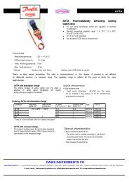
SIKA VTR Series <strong>Turbine</strong> <strong>Flow</strong> <strong>Sensor</strong><br />
Extra robust, impressively precise<br />
SIKA's VTR turbine flow sensor allows you to determine<br />
precisely, dependably and easily the flow rates of different<br />
liquids, such as water and oils, under the most severe<br />
conditions.<br />
The VTR sensor is particularly robust and, due to the<br />
wide range of nominal diameters and three different pickups,<br />
can cope with even the most severe conditions.<br />
How it works<br />
OASIS VTR for use in<br />
• Cooling circuits,<br />
• Petrochemicals,<br />
• Chemical industry,<br />
• Water conditioning,<br />
• Plastics,<br />
• Hydraulics.<br />
The VTR sensor consists of the measuring turbine and<br />
a pick-up mounted on the outside.<br />
The liquid flows into the measuring turbine and causes<br />
the rotor to move. Due to the characteristic internal diameter<br />
the speed of rotation is directly proportional to<br />
the flow rate.<br />
The moving rotor blades are detected by the pick-up<br />
and this is converted into a pulsed signal proportional<br />
to the flow rate.<br />
The characteristic variable is the K-factor (pulses per<br />
liter) which is specific to each measuring unit, is determined<br />
by calibration and specified on the name plate. A five point<br />
calibration report can be supplied on request.<br />
Technical data<br />
Linearity ± 0,5 % of measured value<br />
Repeatability ± 0,05 % of measured value<br />
Response time < 50 ms up to DN 40;<br />
> 50 ms above DN 300<br />
Process –<br />
connections<br />
Flange: DIN, ANSI,<br />
others on request<br />
thread (up to DN 50 only):<br />
pipe ISO 228 or NPT thread<br />
Pressure drop 280 mbar at 100%<br />
measurement range (density<br />
1, viscosity 1 cSt<br />
Maximum pressure<br />
Threaded connection: 250 bar<br />
Flanged connection:<br />
corresponding to flange<br />
specification<br />
All figures specified apply to viscosities up to 5 cSt.<br />
Higher viscosities on request.<br />
Materials<br />
<strong>Turbine</strong> body<br />
Flange<br />
Rotor<br />
Bearing support<br />
Rotor bearing<br />
ANSI 304 stainless steel,<br />
ANSI 316 optional<br />
ANSI 105 carbon steel, ANSI 304 or<br />
ANSI 316 stainless steel optional<br />
up to VTR 1020: ANSI 430 stainless<br />
steel,<br />
above VTR 1020 stainless steel with<br />
molybdenum<br />
ANSI 304 stainless steel,<br />
ANSI 31 6 optional<br />
Tungsten carbide plain bearing, others<br />
(e.g. ball bearings) on request
<strong>Flow</strong> range and dimensions<br />
Type Size <strong>Flow</strong> range Dimensions<br />
DN [ m 3 /h ] [ l/min ] A<br />
( ISO 228 )<br />
B<br />
[ mm ]<br />
C max<br />
[ mm ]<br />
VTR 1010 10 0,11 ... 1,1 1,8 ... 18,3 G ½ 64 150 127<br />
VTR1015-S 15 0,22.. ...2,2 3,7.... .....36,7 G¾ 64 150 127<br />
VTR 1015 15 0,4..........4 6,7.........66,7 G¾ 64 150 127<br />
VTR1020 20 0,8... .......8 13.3........133 G¾ 83 150 140<br />
VTR 1025 25 1,6.. ...... 16 26, 7.... ....267 G1 88 200 152<br />
VTR 1040 40 3,4... .....34 56,7.. ......567 G 1 1 /2 114 200 178<br />
VTR 1050 50 6,8... .....68 113... ....1133 G2 132 200 197<br />
VTR 1075 75 13,5.. ...135 225.. .....2250 — — 200 254<br />
VTR 11 00 100 27.. .....270 450.. .....4500 — — 300 356<br />
VTR 11 50 150 55.......550 917... ....9167 — — 300 360<br />
VTR 1200 200 110. ..1100 1833... 18333 — — 350 457<br />
VTR 1250 250 190.. .1900 3173.. .31730 — 350 457<br />
VTR 1300 300 270. ..2700 4509. ..45090 — 400 457<br />
D<br />
[ mm ]
Three different pick-ups available for the different measurement tasks<br />
VISPP<br />
Inductive pick-up coil<br />
• Fitted as standard<br />
• Inexpensive sensor<br />
• Supplies a sinusoidal output<br />
signal proportional to the flow rate<br />
• No supply voltage<br />
VIII-2SOO/N<br />
Inductive proximity sensor<br />
• Output signal, square-wave<br />
• DC-decoupled by optical<br />
coupler<br />
• Output signal PNP- or<br />
NPN-switching as desired<br />
VILI-2SOO/Ex pick-up with<br />
MK13-VP-ExO isolation<br />
amplifier<br />
• For use in explosion-hazard area<br />
• Intrinsically safe inductive<br />
proximity switch<br />
• Isolation amplifier with intrinsically<br />
safe input circuit to be installed<br />
outside the explosion-hazard area<br />
• <strong>Sensor</strong> and amplifier can only be<br />
used together<br />
Temperature<br />
range<br />
Supply voltage<br />
Protection class IP 54<br />
Electrical<br />
connection<br />
-20°C to +120°C<br />
not necessary<br />
Amphenol plug<br />
connection<br />
MS 10 SL 3102<br />
(supplied)<br />
Temperature<br />
range<br />
Supply<br />
voltage<br />
Protection class IP 54<br />
-20°C to +120°<br />
7 to 30 VDC<br />
Electrical connection Connector<br />
09-0430-10-04.<br />
connecting lead<br />
can be supplied in<br />
different lengths<br />
Temperature<br />
range<br />
Supply voltage<br />
Protection class<br />
Electrical<br />
connection<br />
Certificate of<br />
conformity<br />
-20°Cto+85°C<br />
from isolation<br />
amplifier<br />
lP54<br />
Connector<br />
09-0430-1 0-04,<br />
connecting lead can<br />
be supplied in<br />
different lengths<br />
EExia IIC<br />
MK 13-VP-EXO isolation<br />
amplifier technical data<br />
Input<br />
Frequency signal<br />
from VILI-2S00/EX<br />
Output<br />
Supply voltage<br />
PNP frequency<br />
signal, short circuit<br />
proof, max 100 mA<br />
10 to 30 VDC<br />
Protection class IP 20<br />
Display<br />
Enclosure for<br />
top-hat rail<br />
fitting<br />
Certificate of<br />
conformity<br />
LEDs: Green: ready<br />
Yellow: signal<br />
frequency<br />
Plastic<br />
71 x 18 x 89<br />
(h x w x d)<br />
EEx ia IIC T6 ... T4
Electronics<br />
A wide range of OASIS display and evaluation units, with<br />
and without monitoring, are available for further processing<br />
of the signal:<br />
• Programmable flow and volume measuring<br />
equipment, display of flow rate and total and choice of<br />
various units of measurement. Three programmable<br />
alarm contacts for setpoint monitoring. RS 232 C<br />
serial interface or 0/4 - 20 mA or 0 - 10 V analogue<br />
output..<br />
• Electronic transducer<br />
which converts the measurement signal into a<br />
standard signal. This allows the following outputs to<br />
be selected 0/4 mA - 20 mA and 0 - 10 V .<br />
• Electronic flow monitoring devices with two freely<br />
selectable alarm points.<br />
• Microprocessor-controlled batch controller.<br />
• Electronic frequency dividers. Conversion of a high<br />
sensor output frequency into a lower frequency for<br />
evaluation units.<br />
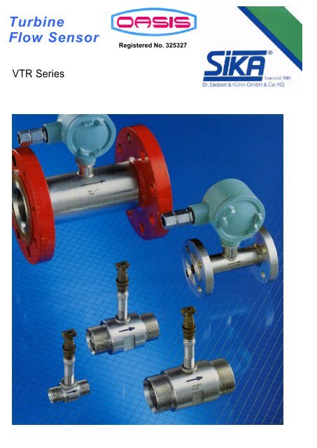
OASIS turbine flow sensor with different<br />
process connections<br />
Installation instructions VTR with male threads for nominal diameter DN 10...DN 50<br />
Often the best measurement range can only be achieved<br />
by selecting a smaller nominal diameter for the turbine<br />
flow sensor than that of the process line.<br />
VTR as flanged version for nominal diameter DN 10...DN 300<br />
OASIS INSTRUMENTS CO.<br />
2-2-103 to 108 Ranigunj<br />
Ganesh Chamber, 2nd Floor<br />
Secunderabad - 500 003<br />
Andhra Pradesh, India<br />
Telefax: +91-40-40025290<br />
E-mail : oasis_instruments@yahoo.co.in, info@oasisinstruments.<strong>com</strong><br />
Url: www.oasisinstruments.<strong>com</strong>