x86-64 Instructions and ABI 1 Introduction 2 Registers 3 Calling ...
x86-64 Instructions and ABI 1 Introduction 2 Registers 3 Calling ...
x86-64 Instructions and ABI 1 Introduction 2 Registers 3 Calling ...

Create successful ePaper yourself
Turn your PDF publications into a flip-book with our unique Google optimized e-Paper software.
CMSC 22620<br />
Spring 2009<br />
Implementation<br />
of<br />
Computer Languages<br />
<strong>x86</strong>-<strong>64</strong> <strong>Instructions</strong> <strong>and</strong> <strong>ABI</strong><br />
H<strong>and</strong>out 3<br />
April 14, 2009<br />
1 <strong>Introduction</strong><br />
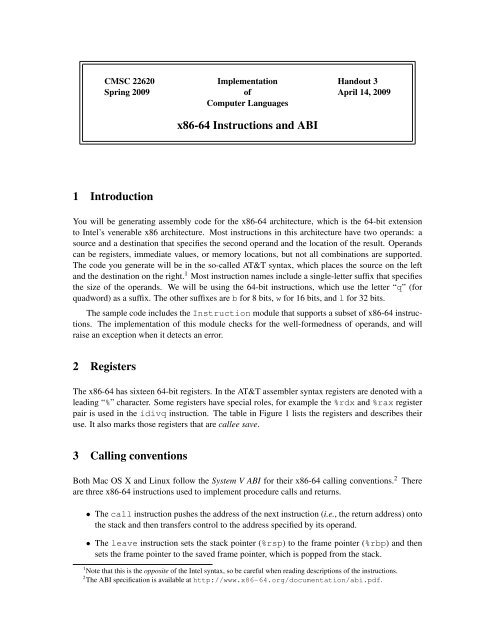
You will be generating assembly code for the <strong>x86</strong>-<strong>64</strong> architecture, which is the <strong>64</strong>-bit extension<br />
to Intel’s venerable <strong>x86</strong> architecture. Most instructions in this architecture have two oper<strong>and</strong>s: a<br />
source <strong>and</strong> a destination that specifies the second oper<strong>and</strong> <strong>and</strong> the location of the result. Oper<strong>and</strong>s<br />
can be registers, immediate values, or memory locations, but not all combinations are supported.<br />
The code you generate will be in the so-called AT&T syntax, which places the source on the left<br />
<strong>and</strong> the destination on the right. 1 Most instruction names include a single-letter suffix that specifies<br />
the size of the oper<strong>and</strong>s. We will be using the <strong>64</strong>-bit instructions, which use the letter “q” (for<br />
quadword) as a suffix. The other suffixes are b for 8 bits, w for 16 bits, <strong>and</strong> l for 32 bits.<br />
The sample code includes the Instruction module that supports a subset of <strong>x86</strong>-<strong>64</strong> instructions.<br />
The implementation of this module checks for the well-formedness of oper<strong>and</strong>s, <strong>and</strong> will<br />
raise an exception when it detects an error.<br />
2 <strong>Registers</strong><br />
The <strong>x86</strong>-<strong>64</strong> has sixteen <strong>64</strong>-bit registers. In the AT&T assembler syntax registers are denoted with a<br />
leading “%” character. Some registers have special roles, for example the %rdx <strong>and</strong> %rax register<br />
pair is used in the idivq instruction. The table in Figure 1 lists the registers <strong>and</strong> describes their<br />
use. It also marks those registers that are callee save.<br />
3 <strong>Calling</strong> conventions<br />
Both Mac OS X <strong>and</strong> Linux follow the System V <strong>ABI</strong> for their <strong>x86</strong>-<strong>64</strong> calling conventions. 2 There<br />
are three <strong>x86</strong>-<strong>64</strong> instructions used to implement procedure calls <strong>and</strong> returns.<br />
• The call instruction pushes the address of the next instruction (i.e., the return address) onto<br />
the stack <strong>and</strong> then transfers control to the address specified by its oper<strong>and</strong>.<br />
• The leave instruction sets the stack pointer (%rsp) to the frame pointer (%rbp) <strong>and</strong> then<br />
sets the frame pointer to the saved frame pointer, which is popped from the stack.<br />
1 Note that this is the opposite of the Intel syntax, so be careful when reading descriptions of the instructions.<br />
2 The <strong>ABI</strong> specification is available at http://www.<strong>x86</strong>-<strong>64</strong>.org/documentation/abi.pdf.
Register Callee Save Description<br />
%rax<br />
result register; also used in idiv <strong>and</strong><br />
imul instructions.<br />
%rbx yes miscellaneous register<br />
%rcx<br />
fourth argument register<br />
%rdx third argument register; also used in<br />
idiv <strong>and</strong> imul instructions.<br />
%rsp<br />
stack pointer<br />
%rbp yes frame pointer<br />
%rsi<br />
second argument register<br />
%rdi<br />
first argument register<br />
%r8 fifth argument register<br />
%r9 sixth argument register<br />
%r10 miscellaneous register<br />
%r11 miscellaneous register<br />
%r12-%r15 yes miscellaneous registers<br />
Figure 1: The <strong>x86</strong>-<strong>64</strong> general-purpose registers<br />
• The ret instruction pops the return address off the stack <strong>and</strong> jumps to it.<br />
The registers %rbp, %rbx, <strong>and</strong> %r12-%r15 are callee save.<br />
3.1 Arguments<br />
The first six arguments to a function are passed in registers. Any additional arguments are passed<br />
on the stack in the memory-argument area (see Figure 2). The %rax register is used to return the<br />
first result <strong>and</strong> the %rdx register is used to return a second result.<br />
3.2 Stack frames<br />
The stack grows from higher addresses to lower addresses. The <strong>ABI</strong> uses two registers to access<br />
the stack: the frame pointer (%rbp), which points to the base of the frame, <strong>and</strong> the stack pointer<br />
(%rsp), which points to the top of the frame. Figure 2 shows the layout of the frame. Normally,<br />
the frame pointer is used to address data in the frame, such as the incoming parameters <strong>and</strong> local<br />
variables.<br />
The <strong>ABI</strong> requires that stack frames be aligned on 16-byte boundaries. Specifically, the end of<br />
the argument area (%rbp+16) must be a multiple of 16. This requirement means that the frame<br />
size should be padded out to a multiple of 16 bytes.<br />
3.3 Procedure-calling protocol<br />
The protocol for procedure calls can be broken into four pieces; two each for the caller <strong>and</strong> callee.<br />
We describe these in the order that the happen.<br />
2
8n+16(%rbp)<br />
16(%rbp)<br />
8(%rbp)<br />
(%rbp)<br />
-8(%rbp)<br />
memory argument n<br />
...<br />
memory argument 0<br />
saved return address<br />
saved %rbp register<br />
locals etc.<br />
Previous frame<br />
Current frame<br />
(%rsp)<br />
outgoing arguments<br />
Figure 2: Stack-frame layout<br />
3.3.1 Procedure call<br />
The caller-side of a procedure call involves saving any caller-save registers that are live across the<br />
call, loading the arguments into the appropriate registers <strong>and</strong> stack locations, <strong>and</strong> then executing<br />
the call instruction. In the Figure 2, the stack frame includes an area for outgoing arguments.<br />
It is also possible to allocate this memory for each call, in which case the caller is responsible for<br />
deallocating it upon return.<br />
3.3.2 Procedure entry<br />
Upon entry, a callee needs to initialize its linkage <strong>and</strong> stack frame. This initialization is accomplished<br />
by the following sequence:<br />
pushq<br />
movq<br />
subq<br />
%rbp<br />
%rsp,%rbp<br />
$N,%rsp<br />
where N is the size of the callee’s stack frame. Once the linkage is established, the callee may<br />
choose to save any callee-save registers that it uses.<br />
3.3.3 Procedure exit<br />
Once the procedure has finished execution, the callee performs the procedure-exit protocol. This<br />
protocol involves putting the result in %rax, deallocating the stack frame, <strong>and</strong> returning control to<br />
the caller. The following code sequence h<strong>and</strong>les the latter two steps:<br />
3
leave<br />
ret<br />
3.3.4 Procedure return<br />
If the caller is allocating stack space for arguments on a per-call basis, then it is responsible for<br />
deallocating the space upon return.<br />
4 <strong>Instructions</strong><br />
For the project, you use a small subset of the <strong>x86</strong>-<strong>64</strong> instructions (mostly the <strong>64</strong>-bit integer operations<br />
plus control-flow operations).<br />
4.1 Oper<strong>and</strong>s<br />
There are three basic kinds of oper<strong>and</strong>s: registers, immediates (which are numbers preceded by the<br />
“$” character in assembly code), <strong>and</strong> memory addresses. We use reg to denote registers, imm32<br />
<strong>and</strong> imm<strong>64</strong> to denote immediates, <strong>and</strong> mem to denote memory addresses in the discussion below.<br />
Since we are computing with <strong>64</strong>-bit values, 32-bit immediates (imm32 ) are sign-extended to <strong>64</strong><br />
bits.<br />
The <strong>x86</strong>-<strong>64</strong> supports a number of different modes for addressing memory. The following table<br />
describes the syntax of these modes <strong>and</strong> the effective addresses that they define:<br />
Syntax Address Description<br />
(reg) reg Base addressing<br />
d(reg) reg + d Base plus displacement addressing<br />
d(reg, s) (s × reg) + d Scaled index plus displacement; s ∈<br />
{2, 4, 8}<br />
d(reg 1 , reg 2 , s) reg 1 + (s × reg 2 ) + d Base plus scaled index <strong>and</strong> displacement;<br />
s ∈ {2, 4, 8}<br />
In this syntax, d <strong>and</strong> s are numbers (without the leading “$”).<br />
4.2 Opcodes<br />
The following table lists the <strong>x86</strong>-<strong>64</strong> instructions that you will need for the project. For each instruction,<br />
we have included the various formats that are supported. <strong>and</strong> a description of the operation.<br />
addq reg 1 , reg 2 reg 2 ← reg 2 + reg 1<br />
addq reg, mem M[mem] ← M[mem] + reg<br />
addq imm32 , reg reg ← reg + imm32<br />
addq imm32 , mem M[mem] ← M[mem] + imm32<br />
addq mem, reg reg ← reg + M[mem]<br />
4
<strong>and</strong>q reg 1 , reg 2 reg 2 ← reg 2 AND reg 1<br />
<strong>and</strong>q reg, mem M[mem] ← M[mem] AND reg<br />
<strong>and</strong>q imm32 , reg reg ← reg AND imm32<br />
<strong>and</strong>q imm32 , mem M[mem] ← M[mem] AND imm32<br />
<strong>and</strong>q mem, reg reg ← reg AND M[mem]<br />
call lab procedure call<br />
call ∗reg procedure call (register indirect)<br />
call ∗(reg) procedure call (memory indirect)<br />
cmpq reg 1 , reg 2 ccode ← TEST(reg 2 − reg 1 )<br />
cmpq reg, mem ccode ← TEST(M[mem] − reg)<br />
cmpq mem, reg ccode ← TEST(reg − M[mem])<br />
cmpq imm32 , reg ccode ← TEST(reg − imm32 )<br />
cmpq imm32 , mem ccode ← TEST(M[mem] − imm32 )<br />
idivq reg %rax ← %rdx : %rax DIV reg<br />
%rdx ← %rdx : %rax MOD reg<br />
idivq mem %rax ← %rdx : %rax DIV M[mem]<br />
%rdx ← %rdx : %rax MOD M[mem]<br />
imulq reg 1 , reg 2 reg 2 ← reg 2 × reg 1<br />
imulq mem, reg reg ← reg × M[mem]<br />
imulq imm32 , reg reg ← reg × imm32<br />
ja lab jump to lab if above (CF = 0 ∧ ZF = 0)<br />
jae lab jump to lab if above or equal (CF = 0)<br />
jb lab jump to lab if below (CF = 1)<br />
jbe lab jump to lab if below or equal (CF = 1 ∧ ZF = 1)<br />
je lab jump to lab if equal (ZF = 1)<br />
jg lab jump to lab if greater (ZF = 0 ∧ SF = OF)<br />
jge lab jump to lab if greater or equal (SF = OF)<br />
jl lab jump to lab if less (SF ≠ OF)<br />
jle lab jump to lab if less or equal (ZF = 1 ∧ SF ≠ OF)<br />
jne lab jump to lab if not equal (ZF = 0)<br />
jns lab jump to lab if not sign flag (SF = 0)<br />
js lab jump to lab if if sign flag (SF = 1)<br />
jmp lab jump to lab<br />
jmp ∗reg jump to the address in reg<br />
jmp ∗(reg) jump to the address in M[reg]<br />
leaq mem, reg reg ← mem (load effective address)<br />
leave<br />
%rsp ← %rbp; %rbp ← M[%rsp];<br />
%rsp ← %rsp + 8.<br />
movabsq lab, reg reg ← lab<br />
movq reg 1 , reg 2 reg 2 ← reg 1<br />
movq reg, mem M[mem] ← reg<br />
movq mem, reg reg ← M[mem]<br />
movq imm32 , reg reg ← imm32<br />
movq imm<strong>64</strong> , reg reg ← imm<strong>64</strong><br />
orq reg 1 , reg 2 reg 2 ← reg 2 OR reg 1<br />
orq reg, mem M[mem] ← M[mem] OR reg<br />
5
orq imm32 , reg reg ← reg OR imm32<br />
orq imm32 , mem M[mem] ← M[mem] OR imm32<br />
orq mem, reg reg ← reg OR M[mem]<br />
pushq reg %rsp ← %rsp − 8; M[%rsp] ← reg<br />
pushq mem %rsp ← %rsp − 8; M[%rsp] ← M[mem]<br />
pushq imm32 %rsp ← %rsp − 8; M[%rsp] ← imm32<br />
ret<br />
return from procedure call<br />
salq imm32 , reg reg ← reg imm32 (arithmetic shift)<br />
sarq imm32 , mem mem ← mem >> imm32<br />
shrq imm32 , reg reg ← reg >> imm32 (logical shift)<br />
shrq imm32 , mem mem ← mem >> imm32<br />
subq reg 1 , reg 2 reg 2 ← reg 2 − reg 1<br />
subq reg, mem M[mem] ← M[mem] − reg<br />
subq imm32 , reg reg ← reg − imm32<br />
subq imm32 , mem M[mem] ← M[mem] − imm32<br />
subq mem, reg reg ← reg − M[mem]<br />
xorq reg 1 , reg 2 reg 2 ← reg 2 XOR reg 1<br />
xorq reg, mem M[mem] ← M[mem] XOR reg<br />
xorq imm32 , reg reg ← reg XOR imm32<br />
xorq imm32 , mem M[mem] ← M[mem] XOR imm32<br />
xorq mem, reg reg ← reg XOR M[mem]<br />
Revision history<br />
April 26, 2009 Fixed description of imulq instruction to match code.<br />
April 25, 2009 Fixed stack-frame picture.<br />
April 15, 2009 The pushq instruction also supports imm32 oper<strong>and</strong>s. Also added note about sign<br />
extension of 32-bit immediates.<br />
April 14, 2009 Fixed table in Section 4.2: changed addq to <strong>and</strong>q <strong>and</strong> changed popq to pushq.<br />
6