Watts TK-9A Backflow Preventer Test Kit - Clean My Water
Watts TK-9A Backflow Preventer Test Kit - Clean My Water
Watts TK-9A Backflow Preventer Test Kit - Clean My Water

You also want an ePaper? Increase the reach of your titles
YUMPU automatically turns print PDFs into web optimized ePapers that Google loves.
IS-<strong>TK</strong>-<strong>9A</strong><br />
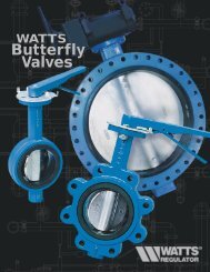
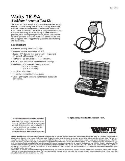
<strong>Watts</strong> <strong>TK</strong>-<strong>9A</strong><br />
<strong>Backflow</strong> <strong>Preventer</strong> <strong>Test</strong> <strong>Kit</strong><br />
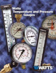
The <strong>Watts</strong> No. <strong>TK</strong>-9 Model “A” <strong>Backflow</strong> <strong>Preventer</strong> <strong>Test</strong> <strong>Kit</strong> is a<br />
compact portable testing device made for testing all Reduced<br />
Pressure Zone <strong>Backflow</strong> Prevention Assemblies and Double<br />
Check Valve Assemblies. The <strong>TK</strong>-<strong>9A</strong> is easily connected to any<br />
RPZ device enabling accurate testing of zone differential<br />
pressure, relief valve opening differential, fouled check valves<br />
or similar problems that visual inspections cannot locate. The<br />
unit is supplied with a rugged carrying case for easy handling<br />
and accessibility.<br />
Specifications<br />
• Maximum working pressure – 175 psi.<br />
• Maximum working temperature – 210°F.<br />
• Gauge - 4 1 ⁄2" diameter face dual scale 0 – 15 psid and<br />
0-1 kg/cm2, ±2% accuracy full scale.<br />
•<strong>Test</strong> Valves – (2) ball valves and (1) needle valve.<br />
• Hoses – (3) 3’ with female threaded swivel couplings.<br />
• Adaptors – (3) 1 ⁄4" threaded coupling adaptors<br />
(3) 1 ⁄2" x 1 ⁄4" bushings<br />
(3) 3 ⁄4" x 1 ⁄4" bushings<br />
•1– 16" securing strap.<br />
•1– Moisture resistant instruction guide.<br />
• Case – light weight, shock resistant molded plastic with<br />
foam inserts.<br />
For digital printout model test kit, request F-<strong>TK</strong>-DL.<br />
Limited Warranty: <strong>Watts</strong> Regulator Company warrants each product to be free from defects in material and workmanship under normal usage for a period of one year from the<br />
date of original shipment. In the event of such defects within the warranty period, the Company will, at its option, replace or recondition the product without charge. This shall constitute<br />
the sole and exclusive remedy for breach of warranty, and the Company shall not be responsible for any incidental, special or consequential damages, including without limitation,<br />
lost profits or the cost of repairing or replacing other property which is damaged if this product does not work properly, other costs resulting from labor charges, delays, vandalism,<br />
negligence, fouling caused by foreign material, damage from adverse water conditions, chemical, or any other circumstances over which the Company has no control. This<br />
warranty shall be invalidated by any abuse, misuse, misapplication or improper installation of the product. THIS WARRANTY IS IN LIEU OF ALL OTHER WARRANTIES, EXPRESS<br />
OR IMPLIED, INCLUDING ANY IMPLIED WARRANTIES OF MERCHANTABILITY OR FITNESS FOR A PARTICULAR PURPOSE. Any implied warranties that are imposed by law<br />
are limited in duration to one year.<br />
Some States do not allow limitations on how long an implied warranty lasts, and some States do not allow the exclusion or limitation of incidental or consequential damages.<br />
Therefore the above limitations may not apply to you. This Limited Warranty gives you specific legal rights, and you may have other rights that vary from State to State.You should<br />
consult applicable state laws to determine your rights.
No. <strong>TK</strong>-9 Model “A” <strong>Test</strong> <strong>Kit</strong><br />
Reduced Pressure Zone <strong>Backflow</strong> <strong>Preventer</strong>s must be<br />
inspected and tested periodically,<br />
in accordance with local codes, to ensure proper operation of<br />
check valves within the unit. A differential pressure gauge is<br />
recommended for <strong>Test</strong> No. 1 rather than a manometer for the<br />
following reasons: It utilizes minimum time to perform the test. It<br />
eliminates the necessity of closing the inlet ball valve which<br />
could release pipe scale and foreign matter into the backflow<br />
preventer. Only a slight amount of water is ‘spilled’ in test. A<br />
mercury manometer could cause a pollution hazard.<br />
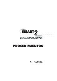
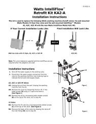
<strong>Test</strong> Set Up<br />
Reduced Pressure Zone Assembly<br />
Close Valves A, B and C on <strong>Test</strong> <strong>Kit</strong>.<br />
Connect high side hose to test cock #2<br />
Connect low side hose to test cock #3. Close shutoff #2.<br />
Open test cocks #2 and #3.<br />
Open vent valve C.<br />
Open ‘high’ valve A and bleed to atmosphere until all the air<br />
is expelled.<br />
Close valve A. Open ‘low’ valve B and bleed to atmosphere<br />
until all air is expelled. Close ‘low’ valve B. Close ‘vent’ valve C.<br />
Connect vent hose to test cock #4.<br />
<strong>Test</strong> Procedure<br />
Reduced Pressure Zone Assembly<br />
Field <strong>Test</strong> Equipment Required<br />
Reduced Pressure Zone <strong>Backflow</strong> <strong>Preventer</strong> <strong>Test</strong> <strong>Kit</strong><br />
<strong>Test</strong> No. 1<br />
Purpose: To test check valve No. 2 for tightness against<br />
reverse flow.<br />
Requirements: Valve must be tight against reverse flow under<br />
all pressure differentials. Slowly open the high valve A and the<br />
vent valve C, and keep the low valve B closed. Open test cock<br />
#4. Indicated pressure differential will decrease slightly. If pressure<br />
differential continues to decrease (until the vent opens)<br />
check valve #2 is reported as leaking.<br />
<strong>Test</strong> No. 4<br />
Purpose: To test operation of pressure differential relief valve.<br />
Requirements: The pressure differential relief valve must<br />
operate to maintain the “zone” between the two check valves<br />
at least 2 psi less than the supply pressure. Close vent valve C.<br />
Open high valve A. Open the low valve B very slowly until the<br />
differential gauge needle starts to drop. Hold the valve at this<br />
position and observe the gauge reading at the moment the first<br />
discharge is noted from the relief valve. Record this as the<br />
opening differential pressure of the relief valve.<br />
Note: It is important that the differential gauge needle drops slowly.<br />
Close test cocks #2 and #3. Use vent hose to relieve pressure<br />
from test kit by opening valves A, B and C. Remove all test<br />
equipment and open shutoff #2.<br />
Auxiliary<br />
<strong>Test</strong> Cock<br />
(A)<br />
High Hose<br />
(Color - Yellow)<br />
Ball Type<br />
<strong>Test</strong> Valves<br />
(C)<br />
(B)<br />
Needle<br />
Valve<br />
Low Hose<br />
(Color - White or Red)<br />
Vent Hose<br />
(Color - Blue)<br />
<strong>Test</strong> No. 2<br />
Purpose: To test shutoff #2 for tightness.<br />
Requirements: After passing <strong>Test</strong> No. 1, continue to <strong>Test</strong> No.<br />
2 by closing test cock #2. The indicated pressure differential will<br />
decrease slightly. If pressure differential continues to decrease<br />
(approaching “zero”), shutoff #2 is reported to be “leaking”.<br />
<strong>Test</strong> Cock<br />
No. 1<br />
<strong>Test</strong> Cock<br />
No. 2<br />
<strong>Test</strong> Cock<br />
No. 3<br />
<strong>Test</strong> Cock<br />
No. 4<br />
<strong>Test</strong> No. 3<br />
Purpose: To test Check Valve No. 1 for tightness.<br />
Check Valve<br />
No. 1<br />
Requirements: Valve must be tight against reverse flow under<br />
all pressure differentials. Close high valve A and open test cock<br />
#2. Close test cock #4. Disconnect vent hose at test cock #4.<br />
Open valves B and C, bleeding to atmosphere. Then closing<br />
valve B restores the system to a normal static condition.<br />
Observe the pressure differential gauge. If there is a decrease in<br />
the indicated value, Check Valve No. 1 is reported as “leaking”.<br />
909QT shown<br />
Shutoff<br />
No. 1<br />
Check Valve<br />
No. 2<br />
Shutoff<br />
No. 2<br />
2<br />
Caution: To prevent freezing, hold <strong>Test</strong> <strong>Kit</strong> vertically to drain<br />
differential gauge and hoses prior to placing in case.
Series 909<br />
Reduced Pressure Zone <strong>Backflow</strong> <strong>Preventer</strong><br />
1 1 ⁄4" to 2"<br />
<strong>Test</strong> Cock<br />
No. 1<br />
<strong>Test</strong> Cock<br />
No. 2<br />
<strong>Test</strong> Cock<br />
No. 3<br />
Check Valve<br />
No. 1<br />
<strong>Test</strong> Cock<br />
No. 4<br />
Shutoff<br />
No. 1<br />
Check Valve<br />
No. 2<br />
Shutoff<br />
No. 2<br />
909QT shown<br />
Pressure Differential<br />
Relief Valve<br />
Series 909<br />
Reduced Pressure Zone <strong>Backflow</strong> <strong>Preventer</strong><br />
2 1 ⁄2" to 10"<br />
Gate Valve<br />
Shutoff<br />
No. 1<br />
<strong>Test</strong> cock<br />
No. 3<br />
<strong>Test</strong> cock<br />
No. 4<br />
Gate Valve<br />
Shutoff<br />
No. 2<br />
Air Vent<br />
<strong>Test</strong> cock<br />
No. 1<br />
909NRS shown<br />
<strong>Test</strong> cock<br />
No. 2<br />
Pressure Differential<br />
Relief Valve<br />
Series 009<br />
Reduced Pressure Zone <strong>Backflow</strong> <strong>Preventer</strong><br />
1<br />
⁄4" to 2"<br />
<strong>Test</strong> cock<br />
No. 1<br />
<strong>Test</strong> cock<br />
No. 3<br />
<strong>Test</strong> cock<br />
No. 4<br />
<strong>Test</strong> cock<br />
No. 2<br />
Shutoff<br />
No. 1<br />
Shutoff<br />
No.2<br />
009QT shown<br />
Pressure Differential<br />
Relief Valve<br />
3
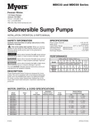
<strong>Test</strong> Procedure<br />
Double Check Valve Assembly<br />
(A)<br />
Ball Type<br />
<strong>Test</strong> Valves<br />
(C)<br />
<strong>Test</strong> Check Valve No. 1<br />
Step 1: Insure shutoff #1 is open, shutoff #2 is closed.<br />
Step 2: Connect high side hose to test cock #3, low side to<br />
test cock #2 and open both test cock #2 and test<br />
cock #3.<br />
Step 3: Open valve C, then open A to bleed air from the high<br />
side. Close valve A, then open B to bleed low side.<br />
Close valve B.<br />
Step 4: Connect vent hose loosely to test cock #1. Open valve<br />
A to vent air from vent hose. Tighten vent hose at test<br />
cock #1, open test cock #1.<br />
Step 5: Close shutoff #1. Slowly loosen hose at test cock #2<br />
until differential gauge rises to 2 psi and retighten<br />
hose. If the differential reading does not decrease,<br />
record check valves as “tight”.<br />
High Hose<br />
(Color - Yellow)<br />
(B)<br />
Needle<br />
Valve<br />
Vent Hose<br />
(Color - Blue)<br />
<strong>Test</strong> Check Valve No. 2<br />
Low Hose<br />
(Color White or Red)<br />
Step 1:<br />
Step 2:<br />
Step 3:<br />
Step 4:<br />
Move the high side hose to test cock #4, low side to<br />
test cock #3 and open both test cock #3 and test<br />
cock #4. Remove vent hose from test cock #1, open<br />
shutoff #1.<br />
Open valve C, then open valve A to bleed air from the<br />
high side. Close valve A, then open valve B to bleed<br />
low side. Close valve B.<br />
Connect vent hose loosely to test cock #1. Open valve<br />
A to vent air from the vent hose. Tighten vent hose at<br />
test cock #1, open test cock #1.<br />
Close shutoff #1, then slowly loosen hose at test cock<br />
#3 until differential gauge rises to 2 psi and retighten<br />
hose. If the differential reading does not decrease,<br />
record check as tight. Remove all hoses and restore<br />
valve to original working condition.<br />
Note: The assembly will fail both the first and second<br />
check valve tests above, if shutoff #2 leaks excessively.<br />
To test for a leaky #2 shutoff, use the following procedure.<br />
1" 007 shown<br />
<strong>Test</strong> Cock<br />
No. 1<br />
<strong>Test</strong> Cock<br />
No. 2<br />
<strong>Test</strong> Cock<br />
No. 3<br />
<strong>Test</strong> Cock<br />
No. 3<br />
<strong>Test</strong> Cock<br />
No. 4<br />
<strong>Test</strong> Cock<br />
No. 4<br />
<strong>Test</strong> for Leaky No. 2 Shutoff<br />
Step 1: Connect the high side to test cock #1, low side to test<br />
cock #4. Open test cock #1 and test cock #4. Close<br />
shutoffs #1 and #2.<br />
Step 2: Close valve C. Open valve A, then open valve B<br />
1<br />
⁄2 turn, loosen hose at test cock #4 to remove air.<br />
Retighten hose.<br />
Step 3: If the differential gauge rises above 0, there is excessive<br />
leakage at shutoff #2 and it must be replaced to<br />
test the assembly.<br />
<strong>Test</strong> Cock<br />
No. 1<br />
709NRS Shown<br />
<strong>Test</strong> Cock<br />
No. 2<br />
USA: 815 Chestnut St., No. Andover, MA 01845-6098; www.wattsreg.com<br />
Canada: 5435 North Service Rd., Burlington, ONT. L7L 5H7; www.wattscda.com<br />
IS-<strong>TK</strong>-<strong>9A</strong> 0223 EDP# 0834222 © <strong>Watts</strong> Regulator Co., 1996 Printed in U.S.A.