Water Specialist 2H Control Valve Manual - Clean My Water
Water Specialist 2H Control Valve Manual - Clean My Water
Water Specialist 2H Control Valve Manual - Clean My Water

Create successful ePaper yourself
Turn your PDF publications into a flip-book with our unique Google optimized e-Paper software.
<strong>Water</strong> <strong>Specialist</strong> <strong>2H</strong><br />
<strong>Control</strong> <strong>Valve</strong> <strong>Manual</strong>
Page 2<br />
WS<strong>2H</strong> <strong>Control</strong> <strong>Valve</strong> <strong>Manual</strong><br />
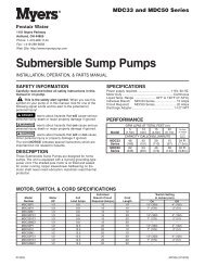
AC Adapter for European Use<br />
1. 220-240 VAC 50Hz input, 24.0 VAC 750mA output.<br />
2. Cable should be one unshielded pair of 22AWG, UV resistant<br />
UL2464 compliant wire.<br />
3. Connector details:<br />
a. Terminate end with one Molex white housing,<br />
P/N 09-50-8043 and four Molex pins, P/N 08-50-0108.<br />
b. Pin 1 = 24.0 VAC White<br />
Pin 2 = Jumper to Pin 3<br />
Pin 3 = Jumper to Pin 2<br />
Pin 4 = 24.0 VAC Black<br />
Molex<br />
Housing<br />
Pin 1<br />
Custom Meter Wiring:<br />
1) Terminate end with a Molex series 2695 housing, part<br />
number 22-01-3037 and (3) Molex series 41572 (or<br />
40445) pins, part number 08-65-0805 (or 97-00-44).<br />
2) Auxilliary meter must be able to operate on 5VDC<br />
Pin 1 = +5VDC,<br />
Pin 2 (Center) = Signal<br />
Pin 3 = Ground<br />
3) Acceptable pulse input is .1 – 999 pulses/gallon, or<br />
.4 –519 pulses / liter.
WS<strong>2H</strong> <strong>Control</strong> <strong>Valve</strong> <strong>Manual</strong> Page 3<br />
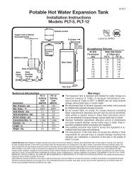
Relay 2 Output<br />
Dry Contacts<br />
Separate<br />
Source Inlet<br />
Motor Drive<br />
Non<br />
Functional<br />
Relay 1 Output<br />
Dry Contacts<br />
Optional System Board, Required For<br />
Relay Output And Separate Source Inlet<br />
1) Relay outputs 1 & 2 are N.O. SPST dry contacts.<br />
2) Maximum power through relays to be:<br />
a. 3A, 30 VDC<br />
b. 3A, 30 VAC<br />
3) Separate source inlet drives require connection to a<br />
V3063 or V3063BSPT motorized alternating valve<br />
(MAV).<br />
Motorized Drive Operation<br />
Viewing the piston rod through the clear dome is a visual indicator of the<br />
drives current positon. On the WS2 motorized bypass drive viewing the<br />
rod indicates that the unit is in service. Viewing the rod as shown on the<br />
MAV indicates that the common port is currently connected to the “B”<br />
port. If the rod is not visible the unit is offline in the case of a bypass, or<br />
connected to the “A” port of a MAV. This drive logic is reversible to meet<br />
specific plumbing applications by reversing the polarity of the drive<br />
motor wiring harness as shown below.<br />
Piston Rod<br />
Is Visible<br />
"Com" Port<br />
"A" Port<br />
Flow Path<br />
"B" Port<br />
Hold Locking Tab<br />
While Pulling On Wire<br />
Factory Wired<br />
As White Wire<br />
Reversing Motorized Drive Direction<br />
WS2 motorized bypass and MAV drives are factory wired with the white<br />
wire on the right when viewing the wiring harness as shown, reversing<br />
the wires reverses the logic of the drive. The wires can be removed<br />
from the housing by holding down the locking tab in the small window<br />
while applying light pressure to the wire, being careful not to disengage<br />
the wire from its crimped on connector. The wires can then be reinserted,<br />
being sure the locking tab re-engages in the window.
Page 4<br />
WS<strong>2H</strong> <strong>Control</strong> <strong>Valve</strong> <strong>Manual</strong><br />
Wiring Diagram Examples, 2 Unit Systems<br />
Motor Driven Bypass <strong>Manual</strong> Over Ride<br />
Place in center for normal operation.<br />
Up forces online, down forces offline<br />
Display Pod<br />
Two units, no system boards.<br />
Meter<br />
Motor Driven<br />
Bypass<br />
Auxilliray (DP)<br />
Switch Input<br />
All Wiring Connections<br />
Apply To Both Units<br />
Transformer Power<br />
(24 VAC)<br />
Unit 1 Main Drive<br />
Unit 2<br />
Motor<br />
Communication Cable<br />
Simple Alternator<br />
One Alternating <strong>Valve</strong> Replaces<br />
Both Units Motorized Bypass<br />
Meter; No Connection<br />
If Both Units Are<br />
Sharing A Single Meter<br />
No<br />
Connection<br />
Display Pod<br />
Auxilliray (DP)<br />
Switch Input<br />
All Wiring Connections Apply To<br />
Both Units. Connections For<br />
Shared Meter And A MAV<br />
Are Made On Unit 2 Only<br />
Meter<br />
Motorized Alternating <strong>Valve</strong> <strong>Manual</strong> Over Ride<br />
Place in center for normal operation.<br />
Up forces unit 2 online, down forces unit 1 online<br />
Motorized<br />
Alternating <strong>Valve</strong><br />
Transformer Power<br />
(24 VAC)<br />
Unit 1, Plumbed To<br />
"A" Port On MAV<br />
Main Drive<br />
Motor<br />
Communication Cable<br />
Unit 2, Plumbed To<br />
"B" Port On MAV<br />
Motor Driven Bypass <strong>Manual</strong> Over Ride<br />
Place in center for normal operation.<br />
Up forces online, down forces offline<br />
Display Pod<br />
Two unit system, with optional system boards<br />
for relay outputs and separate source inlet<br />
Meter<br />
Motor Driven<br />
Bypass<br />
Auxilliray (DP)<br />
Switch Input<br />
Relay 2 Output<br />
Dry Contacts<br />
Separate<br />
Source Inlet<br />
Motor Drive<br />
Non<br />
Functional<br />
Relay 1 Output<br />
Dry Contacts<br />
Transformer Power<br />
(24 VAC)<br />
Unit 1<br />
Main Drive<br />
Motor<br />
Communication Cable<br />
All Wiring Connections<br />
Apply To Both Units<br />
Unit 2<br />
Input On Slaves Must<br />
Use Master / Slave Port
WS<strong>2H</strong> <strong>Control</strong> <strong>Valve</strong> <strong>Manual</strong> Page 5<br />
Wiring Diagrams<br />
3 & 4 unit systems with no optional system boards<br />
(4 unit shown)<br />
Motor Driven Bypass <strong>Manual</strong> Over Ride<br />
Place in center for normal operation.<br />
Up forces online, down forces offline<br />
Display Pod<br />
Meter<br />
Motor Driven<br />
Bypass<br />
Auxilliray (DP)<br />
Switch Input<br />
Transformer Power<br />
(24 VAC)<br />
Unit 1<br />
Main Drive<br />
Motor<br />
Communication<br />
Cables<br />
All Wiring Connections<br />
Apply To All Units<br />
Unit 2<br />
Unit 3<br />
Unit 4
Page 6<br />
Wiring Diagrams<br />
WS<strong>2H</strong> <strong>Control</strong> <strong>Valve</strong> <strong>Manual</strong><br />
3 & 4 unit systems with optional system boards<br />
for relay outputs and separate source inlet<br />
(4 unit shown)<br />
Motor Driven Bypass <strong>Manual</strong> Over Ride<br />
Place in center for normal operation.<br />
Up forces online, down forces offline<br />
Display Pod<br />
Meter<br />
Motor Driven<br />
Bypass<br />
Auxilliray (DP)<br />
Switch Input<br />
Relay 2 Output<br />
Dry Contacts<br />
Separate<br />
Source Inlet<br />
Motor Drive<br />
Non<br />
Functional<br />
Relay 1 Output<br />
Dry Contacts<br />
Transformer Power<br />
(24 VAC)<br />
Unit 1<br />
Main Drive<br />
Motor<br />
All Wiring Connections<br />
Apply To All Units<br />
Communication<br />
Cables<br />
Unit 2<br />
Input On Slaves Must<br />
Use Master / Slave Port<br />
Unit 3<br />
Unit 4
WS<strong>2H</strong> <strong>Control</strong> <strong>Valve</strong> <strong>Manual</strong> Page 7
Page 8<br />
WS<strong>2H</strong> <strong>Control</strong> <strong>Valve</strong> <strong>Manual</strong>
WS<strong>2H</strong> <strong>Control</strong> <strong>Valve</strong> <strong>Manual</strong> Page 9
Page 10<br />
WS<strong>2H</strong> <strong>Control</strong> <strong>Valve</strong> <strong>Manual</strong>
WS<strong>2H</strong> <strong>Control</strong> <strong>Valve</strong> <strong>Manual</strong> Page 11<br />
Typical User Screens<br />
“REGEN TODAY” will<br />
display when a regeneration<br />
is scheduled, or flash for a<br />
manually set regeneration.<br />
USER 1<br />
USER 1<br />
Displays capacity remaining Does not<br />
display if volumetric capacity is set to OFF.<br />
Capacity remaining can be adjusted in 10 gallon<br />
increments by holding the DOWN arrow for >3 seconds.<br />
USER 2<br />
USER 2<br />
Displays days remaining Does not display if days<br />
override is set to OFF.<br />
Days remaining can be decremented one day at a<br />
time by holding the DOWN arrow >3 seconds.<br />
USER 3<br />
USER 3<br />
Displays time of day.<br />
“HOLD” or “START” REGEN<br />
will flash in all user screens while<br />
the auxiliary input is actuated.<br />
USER 4<br />
USER 4<br />
Displays the unit’s current flow rate.<br />
USER 5<br />
USER 5<br />
Displays total unit volume since<br />
install/reset Individually re-settable<br />
using history reset sequence.<br />
USER 6<br />
USER 6<br />
Displays the current system flow rate<br />
Does not display on single tank units.<br />
USER 7<br />
USER 7<br />
Displays total system volume since install/reset<br />
Individually re-settable using history reset sequence<br />
Does not display on single tank units.<br />
User 1
Page 12<br />
WS<strong>2H</strong> <strong>Control</strong> <strong>Valve</strong> <strong>Manual</strong><br />
Setting Time of Day<br />
SET TIME<br />
Accessed by pressing Set Clock while in the<br />
User Screens. Use UP and DOWN arrows to<br />
scroll hours. AM/PM alternates at midnight.<br />
Return to<br />
Normal Operation<br />
UNIT COUNT ERROR<br />
Error and the slave’s unit number will flash when it is<br />
not detected. Pressing any button will return the user<br />
to the #units set up screen to correct the value.<br />
ERROR SCREEN<br />
Error and its code alternate. The unit returns to home<br />
and flashes its 3 LEDs. The unit continues to try and<br />
function, but must be reset to correct the error screen.<br />
Automatically toggles.
WS<strong>2H</strong> <strong>Control</strong> <strong>Valve</strong> <strong>Manual</strong> Page 13<br />
Installer Setup Screens<br />
Accessed by pressing NEXT and<br />
UP simultaneously for >3 seconds.<br />
Returns to normal operation after 5 minutes.<br />
Set current day and regen days<br />
when set as a 7 day time clock<br />
or hybrid in System Setup 1.<br />
INSTALLER 1<br />
INSTALLER 2<br />
INSTALLER 1<br />
Set volumetric capacity or OFF. OFF will not be an<br />
option if the day control is set to OFF.<br />
X1000 Indicator Illuminates At 10,000 Gallons<br />
Units Range Increments<br />
US<br />
(GAL)<br />
SI<br />
(L)<br />
10-10,000<br />
10,000-100.00 x 1000<br />
100.00-999.00 x 1000<br />
38-38,000<br />
38,000-380.00 x 1000<br />
380.00-3796.2 x 1000<br />
10<br />
100<br />
1000<br />
38<br />
38<br />
3800<br />
INSTALLER 2<br />
Set day override. 1-28 days between regenerations, or if set to<br />
7 day time clock, see 7 day setup below. OFF will display if<br />
selected in Day <strong>Control</strong> screen.<br />
INSTALLER 3<br />
INSTALLER 3<br />
Select time of regen. Use up and down arrows to scroll<br />
hours. AM/PM alternates at midnight. “on0” will be<br />
displayed on units with no time dependent regen control.<br />
(“1” only shows if set for multiple regens.)<br />
INSTALLER 4<br />
INSTALLER 4<br />
Select time of regen. Use up and<br />
down arrows to scroll minutes.<br />
Return To<br />
Normal Operation.<br />
7 Day Option<br />
INSTALLER 5<br />
INSTALLER 5<br />
Select time of 2nd regen<br />
(if configured as a multiple<br />
regenerating unit.)<br />
INSTALLER 2<br />
INSTALLER 2B<br />
INSTALLER 2<br />
7 day time clock option.<br />
Set current day of the week:<br />
1 = Sunday<br />
2 = Monday<br />
3 = Tuesday<br />
4 = Wednesday<br />
5 = Thursday<br />
6 = Friday<br />
7 = Saturday<br />
INSTALLER 2B<br />
Scroll through days 1-7 using the UP and DOWN arrows.<br />
Pressing the Set Clock will toggle regen ON or OFF for<br />
that day. (i.e., regen on Monday.)<br />
INSTALLER 2C<br />
INSTALLER 2C<br />
(i.e., no regeneration on Saturday.)<br />
Installer 3
Page 14<br />
WS<strong>2H</strong> <strong>Control</strong> <strong>Valve</strong> <strong>Manual</strong><br />
System Setup Screens<br />
Returns to normal operation after 5 minutes<br />
Accessed by pressing NEXT and DOWN<br />
simultaneously for >3 seconds.<br />
SYSTEM SETUP 1<br />
SYSTEM SETUP 1<br />
Select country.<br />
US or SI.<br />
This sets the use of a 12 or 24 hour clock<br />
and the display of gallons or liters.<br />
SYSTEM SETUP 2<br />
SYSTEM SETUP 2<br />
Select the total number of units, from 1-4, in a<br />
system. This screen will only allow 1 or 2 if a<br />
system board is not installed.<br />
SYSTEM SETUP 3<br />
SYSTEM SETUP 4<br />
SYSTEM SETUP 3<br />
Select unit flow rate unit add point.<br />
1. If set to 0, all units are online unless one is regenerating.<br />
2. If greater than 0, the system acts as a stage by flow adding units as flow<br />
capacity increases.<br />
3. If set to ALT the system acts as an alternator<br />
system, keeping one unit off line at all times.<br />
The screen will not display if set to 1 unit.<br />
Units Range Increments<br />
US<br />
(GAL) 0-500 1<br />
SI<br />
(L) 0-1896 4<br />
SYSTEM SETUP 4<br />
Single units have a selection of hard water bypass, no hard water bypass or relay operation.<br />
When the units starts a regen, HbP will allow hard water bypass, noHbp and RELAY<br />
will not allow hard water bypass. Systems will allow setting noHbP or RELAY & 2 unit<br />
alternators have an additional selection of ALT-A. Setting noHbP requires a motor driven<br />
bypass, ALT-A requires a motor driven alternator valve on the controlling unit and RELAY<br />
relys on external valving for noHbP control.<br />
SYSTEM SETUP 5<br />
SYSTEM SETUP 5<br />
Select day control type.<br />
Time clock 1-28 day; Time clock 7 day; or OFF.<br />
When volumetric capacity is set, volume regeneration can<br />
be combined with time clock control. OFF will not be an<br />
option if volumetric capacity is OFF.<br />
continued on Page 15
WS<strong>2H</strong> <strong>Control</strong> <strong>Valve</strong> <strong>Manual</strong> Page 15<br />
System Setup Screens (continued)<br />
SYSTEM SETUP 6<br />
SYSTEM SETUP 6<br />
Select regeneration type.<br />
Delayed (dEL-1)<br />
Delayed, 2 regenerations per day (dEL-2)<br />
Delayed, 3 regenerations per day (dEL-3)<br />
Delayed, 4 regenerations per day (dEL-4)<br />
On 0<br />
Delayed with multiple regenerations allowed per day would be<br />
used either to reduce the reserve volume, or to accommodate a<br />
small system relative to the treatment demand.<br />
SYSTEM SETUP 7<br />
SYSTEM SETUP 7<br />
Select reserve calculation ON or OFF.<br />
OFF will schedule a regen when the volumetric<br />
capacity reaches 0. This screen will not display<br />
for “on0” units or systems.<br />
SYSTEM SETUP 8<br />
SYSTEM SETUP 8<br />
Set auxiliary initiated regen.<br />
START TIME REGEN: regeneration will start immediately after 2 cumulative<br />
minutes of switch closure.<br />
START TIME REGEN dEL: regeneration will start at the delayed time after 2<br />
cumulative minutes of switch closure.<br />
START REGEN: regeneration will start immediately upon switch closure.<br />
START REGEN dEL: regeneration will start at the delayed time upon switch closure.<br />
HOLD REGEN: regeneration will not be allowed as long as there is switch closure.<br />
SYSTEM SETUP 9<br />
SYSTEM SETUP 9<br />
Select meter type or pulses.<br />
2.0 meter (type)<br />
1.5 meter (type)<br />
System Pulses<br />
SYSTEM SETUP 9B<br />
SYSTEM SETUP 10<br />
SYSTEM SETUP 9B<br />
Select meter type pulses.<br />
Screen does not show if Pulses or System Pulses is not<br />
selected in the previous screen.<br />
Pulses/ Unit Flow<br />
Units Range Increments<br />
US<br />
(Pulse/Gal)<br />
SI (Pulse/L)<br />
SYSTEM SETUP 10<br />
Separate source inlet. This screen will not<br />
display if a system board is not installed.<br />
0.1 - 30.0<br />
30.0 - 999.0<br />
0.4 - 114.0<br />
114.0 - 519.4<br />
0.1<br />
1.0<br />
0.4<br />
3.8<br />
Return To<br />
Normal Operation
Page 16<br />
WS<strong>2H</strong> <strong>Control</strong> <strong>Valve</strong> <strong>Manual</strong><br />
Timer Screens<br />
Returns to normal operation after 5 minutes.<br />
Accessed by pressing NEXT and DOWN simultaneously<br />
for >3 seconds, then by pressing NEXT and DOWN<br />
simultaneously again for >3 seconds.<br />
TIMER 1-A<br />
TIMER 1-A<br />
Select time of cycle 1.<br />
Cycle Units Range Increments<br />
Backwash<br />
Minutes<br />
1-30<br />
30-95<br />
1<br />
5<br />
A NEXT & DN reset from<br />
this screen unlocks the<br />
setup screens.<br />
Draw<br />
Slow Rinse<br />
Minutes<br />
Minutes<br />
1-30<br />
30-100<br />
100-180<br />
1-30<br />
30-95<br />
1<br />
5<br />
10<br />
1<br />
5<br />
Rinse<br />
Minutes<br />
1-30<br />
30-95<br />
1<br />
5<br />
TIMER 1-B<br />
TIMER 1-B<br />
Select time of cycle 2.<br />
Fill<br />
Minutes<br />
0.1-10.0<br />
10.0-30.0<br />
30.0-99.0<br />
0.1<br />
0.2<br />
1.0<br />
Hold<br />
Minutes<br />
1-30<br />
30-100<br />
100-480<br />
0.1<br />
2.0<br />
10.0<br />
“1” is displayed if<br />
set for more than<br />
one sequence<br />
The following screens only show if the unit is<br />
programmed for multiple regenerations in the<br />
Cycle Setup 2 screen.<br />
TIMER 1-A2<br />
TIMER 1-A2<br />
Select time of alternate regen, cycle 1.<br />
TIMER 1-B2<br />
TIMER 1-B2<br />
Select time of alternate regen, cycle 2.<br />
continued on Page 17
WS<strong>2H</strong> <strong>Control</strong> <strong>Valve</strong> <strong>Manual</strong> Page 17<br />
Timer Screens (continued)<br />
TIMER 2<br />
TIMER 2<br />
Set output 1.<br />
These settings will only be allowed with the system board installed.<br />
Time: Relay is turned on after specified time from the start of regen and is left on for a specified time.<br />
Cycle: Relay is turned on after the start of a specified cycle and is left on for a specified time.<br />
Volume: Relay is turned on, during service flow only, every specified number of volume units and is left on for a specified time.<br />
Volume & Regen: Relay is turned on every specified number of volume units, and is left on for a specified time.<br />
STbY: Relay would be used to control external valving, closing for unit regeneration, or when it would be offline in system operation.<br />
REGEN: Relay closes when the unit is in regen.<br />
Err: Relay closes when the unit is in any error mode.<br />
TIMER 3<br />
TIMER 3<br />
Set output 2.<br />
These settings will only be allowed with the system board installed.<br />
Time: Relay is turned on after specified time from the start of regen and is left on for a specified time.<br />
Cycle: Relay is turned on after the start of a specified cycle and is left on for a specified time.<br />
Volume: Relay is turned on, during service flow only, every specified number of volume units and is left on for a specified time.<br />
Volume & Regen: Relay is turned on every specified number of volume units and is left on for a specified time.<br />
STbY: Relay would be used to control external valving, closing for unit regeneration, or when it would be offline in system operation.<br />
REGEN: Relay closes when the unit is in regen.<br />
Err: Relay closes when the unit is in any error mode.<br />
TIMER 4<br />
TIMER 4<br />
Select output 1, On trigger set point, per units previously selected.<br />
This screen will not display if the unit does not have a system board, or if STbY was selected as the trigger.<br />
Time: Time after the start of a regen before switch is closed.<br />
Cycle: Select a cycle which will close output 1.<br />
Volume: Volume of water interval during service between switch closures.<br />
Timer 4 and 6 screens will not display if display if STbY, REGEN or Err are selected in TIMER 2 and TIMER 3.<br />
TIMER 5<br />
TIMER 6<br />
TIMER 5<br />
Select output 1 On duration before turning OFF. This screen will<br />
not display if the unit does not have a system board.<br />
TIMER 6<br />
Select output 2, On trigger set point, per units previously selected.<br />
This screen will not display if the unit does not have a system board, or if<br />
STby was selected as the trigger<br />
Time: Time after the start of a regen before switch is closed.<br />
Cycle: Select a cycle which will close output 2.<br />
Volume: Volume of water interval during service between switch closures.<br />
Relay Trigger Settings<br />
Trigger Units Range Increments<br />
Time Minutes :01-20:00 :01<br />
Cycle<br />
Slow Rinse<br />
Volume<br />
Volume<br />
Gallons<br />
1-200<br />
200-1000<br />
100-10000<br />
1-760<br />
Liters 760-13800<br />
13800-38000<br />
Relay Duration Settings<br />
1<br />
5<br />
10<br />
4<br />
19<br />
38<br />
Trigger Units Range Increments<br />
Time Minutes :01-20:00 :01<br />
TIMER 7<br />
TIMER 7<br />
Select output 2 On duration before turning OFF.<br />
This screen will not display if the unit does not have a<br />
system board.<br />
Return To<br />
Normal Operation.
Page 18<br />
WS<strong>2H</strong> <strong>Control</strong> <strong>Valve</strong> <strong>Manual</strong><br />
Cycle Setup Screens<br />
Returns to normal operation after 5 minutes.<br />
Accessed by pressing NEXT and DOWN simultaneously for >3 seconds,<br />
then by pressing NEXT and DOWN simultaneously again for >3 seconds,<br />
then by pressing NEXT and DOWN simultaneously for >3 seconds a third time.<br />
CYCLE SETUP 1-A<br />
CYCLE SETUP 1-A<br />
Select first cycle.<br />
Cycle #<br />
Cycle<br />
Default<br />
CYCLE SETUP 1-B<br />
CYCLE SETUP 1-B<br />
Select second cycle.<br />
1 Backwash<br />
2 Draw<br />
3 2nd Backwash<br />
4 Rinse<br />
5 Fill<br />
6 End<br />
CYCLE SETUP 1-C<br />
CYCLE SETUP 1-C<br />
After cycles are configured, an END is added.<br />
(9 cycles maximum.)<br />
continued on Page 19
WS<strong>2H</strong> <strong>Control</strong> <strong>Valve</strong> <strong>Manual</strong> Page 19<br />
Cycle Setup Screens (continued)<br />
CYCLE SETUP 2<br />
CYCLE SETUP 2<br />
Select regeneration repeats, 1-10 or OFF.<br />
Repeats regeneration cycle sequence 1 a selected number<br />
of times before regenerating a single time with sequence 2.<br />
The following screens only show if the unit is<br />
programmed for multiple regenerations in the<br />
previous screen.<br />
CYCLE SETUP 3-A<br />
CYCLE SETUP 3-A<br />
Select first cycle of “alternate”<br />
regeneration sequence.<br />
CYCLE SETUP 3-B<br />
CYCLE SETUP 3-B<br />
Select second cycle of ‘alternate’<br />
regeneration sequence.<br />
CYCLE SETUP 3-C<br />
CYCLE SETUP 3-C<br />
After cycles are configured, an END is added.<br />
(9 cycles maximum.)<br />
Return To<br />
Normal Operation
Page 20<br />
WS<strong>2H</strong> <strong>Control</strong> <strong>Valve</strong> <strong>Manual</strong><br />
Diagnostic Screens<br />
Accessed by pressing UP and DOWN<br />
simultaneously for >3 seconds.<br />
Returns to normal operation after 5 minutes.<br />
DIAGNOSTIC 1<br />
DIAGNOSTICS 1<br />
Days since the last regeneration.<br />
All Diagnostic History screens are resettable<br />
with the History Reset sequence while in the<br />
Diagnostics1 screen. Holding the Set Clock<br />
and Regen buttons for > 3 seconds initiates a<br />
totalizer or history reset.<br />
DIAGNOSTIC 2<br />
DIAGNOSTICS 2<br />
Gallons or Liters x1000 since the last<br />
regeneration.<br />
DIAGNOSTIC 3<br />
DIAGNOSTICS 3<br />
Reserve history. This screen only appears if valve<br />
is set to calculate Reserve in System Setup 7.<br />
Use arrows to select a day.<br />
0 = Today<br />
1 = Yesterday<br />
6 = 6 days ago (max.)<br />
Reserve Value<br />
DIAGNOSTIC 4<br />
Automatically Toggles<br />
DIAGNOSTICS 4<br />
History of volume used.<br />
Use arrows to select a day.<br />
0 = Today<br />
1 = Yesterday<br />
63 = 63 days ago (max.)<br />
REGEN will display if a<br />
regeneration occurred that day.<br />
Gallons Used<br />
Automatically Toggles<br />
Simultaneously press<br />
UP and DOWN.<br />
DIAGNOSTIC 4-B<br />
DIAGNOSTICS 4-B<br />
Hourly history of volume use. Use<br />
the UP and DOWN arrow to select<br />
the hours of the day from screen 4.<br />
Volume used within the selected hour<br />
Automatically Toggles<br />
Diagnostic 4<br />
continuned on Page 21
WS<strong>2H</strong> <strong>Control</strong> <strong>Valve</strong> <strong>Manual</strong> Page 21<br />
Diagnostic Screens (continued)<br />
DIAGNOSTIC 5<br />
DIAGNOSTICS 5<br />
Maximum flow rate<br />
for the last 28 days.<br />
Max flow rate of the day<br />
Automatically Toggles<br />
Simultaneously press<br />
UP and DOWN.<br />
DIAGNOSTIC 5-B<br />
DIAGNOSTICS 5-B<br />
Hourly history of maximum<br />
flow rate. Use the UP and<br />
DOWN arrow to select the<br />
hours of the day from screen 5.<br />
Max flow within the selected hour<br />
Automatically Toggles<br />
Diagnostics 5<br />
DIAGNOSTIC 6<br />
DIAGNOSTICS 6<br />
Total volume through the unit.<br />
DIAGNOSTIC 7<br />
DIAGNOSTICS 7<br />
System totalizer for the last<br />
63 days. Only displays in a<br />
master unit.<br />
System use for that day<br />
Automatically Toggles<br />
Return To<br />
Normal Operation<br />
Simultaneously press<br />
UP and DOWN.<br />
DIAGNOSTIC 7-B<br />
DIAGNOSTICS 7-B<br />
Hourly system totalizer. Use<br />
the UP and DOWN arrow to<br />
select the hour of the day from<br />
screen 7.<br />
Total system flow for the selected hour<br />
Automatically Toggles<br />
Return To<br />
Normal Operation<br />
Diagnostics 7
Page 22<br />
WS<strong>2H</strong> <strong>Control</strong> <strong>Valve</strong> <strong>Manual</strong><br />
<strong>Valve</strong> History<br />
Returns to normal operation after 5 minutes.<br />
Non-Resettable<br />
Accessed by pressing UP and DOWN simultaneously<br />
for >3 seconds, then by pressing UP and DOWN<br />
simultaneously again for >3 seconds.<br />
HISTORY 1<br />
HISTORY 1<br />
Total days since startup.<br />
Time only accumulates while<br />
the unit is plugged in.<br />
HISTORY 2<br />
HISTORY 2<br />
Total regenerations since startup.<br />
HISTORY 3<br />
HISTORY 3<br />
Total volume since startup.<br />
Return To<br />
Normal Operation
WS<strong>2H</strong> <strong>Control</strong> <strong>Valve</strong> <strong>Manual</strong> Page 23<br />
Treated <strong>Water</strong><br />
Supply<br />
Raw <strong>Water</strong><br />
Inlet<br />
Service<br />
Hard <strong>Water</strong><br />
Supply<br />
To Drain<br />
Raw <strong>Water</strong><br />
Inlet<br />
Backwash
Page 24<br />
WS<strong>2H</strong> <strong>Control</strong> <strong>Valve</strong> <strong>Manual</strong><br />
Hard <strong>Water</strong><br />
Supply<br />
To Drain<br />
Raw <strong>Water</strong><br />
Inlet<br />
Solution Is<br />
Drawn In<br />
Draw<br />
Hard <strong>Water</strong><br />
Supply<br />
To Drain<br />
Raw <strong>Water</strong><br />
Inlet<br />
Slow Rinse
WS<strong>2H</strong> <strong>Control</strong> <strong>Valve</strong> <strong>Manual</strong> Page 25<br />
Hard <strong>Water</strong><br />
Supply<br />
To Drain<br />
Raw <strong>Water</strong><br />
Inlet<br />
Rinse<br />
Treated <strong>Water</strong><br />
Supply<br />
Raw <strong>Water</strong><br />
Inlet<br />
Treated <strong>Water</strong><br />
To Tank<br />
Softwater Fill
Page 26<br />
WS<strong>2H</strong> <strong>Control</strong> <strong>Valve</strong> <strong>Manual</strong><br />
Front Cover and Drive Assembly<br />
Drawing No. Order No. Description Quantity<br />
1 V3068 WS2 POD ASY 1<br />
2 V3241-01 WS2 PC BOARD DISPLAY 1<br />
3 V3248 WS2 CABLE DISPLAY POD 1<br />
4 V3242-01 WS2 PC BOARD VALVE 1<br />
5 V3224-01R WS2 COVER ASY PLATINUM 1<br />
6 V3107-01 WS1 MOTOR ASY 1<br />
7 V3226-01 WS2 DRIVE BRACKET ASY 1<br />
8 V3110 WS1 DRIVE GEAR 12X36 3<br />
9 V3109 WS1 DRIVE GEAR COVER 1<br />
Not Shown V3461 WS2 AC ADAPTER 24V<br />
Not Shown V3461EU WS2 AC ADAPTER 24V EU<br />
1<br />
Not Shown V3461UK WS2 AC ADAPTER 24V UK<br />
10 V3243-01 WS2 PC BOARD SYSTEM Optional<br />
Not Shown V3475-12 WS2 SYS CONNECT CORD 12 FT RED Optional<br />
Not Shown V3475-24 WS2 SYS CONNECT CORD 24 FT BL Optional<br />
Not Shown V3475-36 WS2 SYS CONNECT CORD 36 FT YEL Optional<br />
1<br />
5<br />
7<br />
8<br />
9<br />
2<br />
3<br />
4<br />
6<br />
10
WS<strong>2H</strong> <strong>Control</strong> <strong>Valve</strong> <strong>Manual</strong> Page 27<br />
Drive Cap Assembly, Downflow Piston, Regenerant Piston, Spacer Stack Assembly, Drive Back Plate,<br />
Main Body and Meter<br />
Drawing No. Order No. Description Quantity<br />
1 V3274 WS2 SCREW BTNSKT HD SS3/8-16X2 4<br />
2 V3291 WS2 WASHER SS 3/8 4<br />
3 V3225 WS2 BACK PLATE 1<br />
4 V3066 WS2 DRIVE ASY 1<br />
5 V3289 O-RING 344 1<br />
6 V3204-01 WS2 PISTON 1<br />
7 V3238-01 WS2 BRINE PISTON 1<br />
8 V3065 WS2 STACK ASY 1<br />
Not Shown<br />
V3468<br />
V3465<br />
WS2 PLUG 1/4 HEX NPT (included when ordering V3201-03)<br />
WS2 PLUG 1/4 HEX BSPT (included when ordering V3201BSPT-03)<br />
9<br />
V3201-03 WS2 BODY W/V3468 PLUG<br />
V3201BSPT-03 WS2 BSPT BODY W/V3465 PLUG<br />
1<br />
10 V3223 WS15/WS2 METER CLIP 1<br />
11 V3003-02 WS1.5/<strong>2H</strong> METER COMMERCIAL ASY 1<br />
12 V3118-01 WS1 TURBINE ASY 1<br />
13 V3105 O-RING 215 1<br />
14 V3279 O-RING 346 1<br />
15<br />
V3280 O-RING 332 FOR VALVE BODIES WITH NPT THREADS<br />
V3452 O-RING 230 FOR VALVE BODIES WITH BSPT THREADS<br />
1<br />
16 V3054** WS2 4 IN BASE CLAMP ASY 1<br />
17 V3276 WS2 BOLT HEX SS 5/16-18X1-3/4 1<br />
18 V3269 WS2 NUT 5/16-18 SS HEX 1<br />
Not Shown D1300-01 TOP BAFFLE DFSR CLACK 2/63MM 1<br />
**V3054 WS2 4 IN BASE CLAMP ASY includes a V3276 WS2 BOLT HEX SS 5/16-18X1-3/4 and V3269 WS2 NUT<br />
5/16-18 SS HEX.<br />
11<br />
12<br />
13<br />
N or no mark<br />
indicates<br />
B or indent<br />
indicates<br />
BSPT<br />
10 9 NPT<br />
2<br />
3<br />
4 5<br />
6 7<br />
8<br />
1<br />
2<br />
14<br />
15<br />
16<br />
18<br />
17<br />
Install D1300-01 upper diffuser (not shown) when<br />
using the 4” Quick Dissconnect (V3064)
Page 28<br />
WS<strong>2H</strong> <strong>Control</strong> <strong>Valve</strong> <strong>Manual</strong><br />
Brine <strong>Valve</strong> Body and Injector Components<br />
Drawing No. Order No. Description Quantity<br />
1 V3237-01 WS2 SOFTFILL TUBE ASY 1<br />
2 V3236-01 WS2 INJECTOR TUBE ASY 1<br />
3 V3289 O-RING 344 1<br />
4 V3067 WS2 BRINE BODY ASY 1<br />
5 V3477 WS2 INJECTOR CAP 1<br />
6 V3152 O-RING 135 1<br />
7 V3275 WS2 SCREW BSHD SS 3/8-16X2-1/4 4<br />
8 V3291 WS2 WASHER SS 3/8 4<br />
9 V3162-022* WS1 DLFC 022 FOR 3/4 1<br />
10 V3231 WS2 REFILL FLOW CNTRL RETAINER 1<br />
11 V3277 O-RING 211 1<br />
12 V3105 O-RING 215 1<br />
13 V3150 WS1 SPLIT RING 1<br />
14 V3151 WS1 NUT 1 QC 1<br />
15 V3149 WS1 FTG 1 PVC MALE NPT ELBOW 1<br />
Not Shown V3189 WS1 FTG 3/4&1 PVC SLVNT 90 Optional<br />
V3010-2A WS2 INJECTOR ASY A<br />
V3010-2B WS2 INJECTOR ASY B<br />
V3010-2C WS2 INJECTOR ASY C<br />
16 V3010-2D WS2 INJECTOR ASY D<br />
1<br />
V3010-2E WS2 INJECTOR ASY E<br />
V3010-2F WS2 INJECTOR ASY F<br />
V3010-2G WS2 INJECTOR ASY G<br />
Not Shown V3499** WS2 FITTING CAP 1 IN THREADED 1<br />
15<br />
*Any V3162-XXX flow control may be used.<br />
V3237-01 WS2 SOFTFILL TUBE ASY contains a<br />
V3155 O-RING 112, V3287 O-RING 110 and a V3288<br />
O-RING 206.<br />
14<br />
13<br />
12<br />
11<br />
10<br />
9<br />
V3236-01 WS2 INJECTOR TUBE ASY contains a<br />
V3285 O-RING 213 and a V3286 O-RING 216.<br />
V3010-2X injectors contains a V3283 O-RING 117 and<br />
a V3284 O-RING 114.<br />
** Install V3499 on V3149 if valve is to be set up as a<br />
backwash only valve<br />
8<br />
7<br />
5<br />
3<br />
1<br />
2<br />
4<br />
16<br />
6
WS<strong>2H</strong> <strong>Control</strong> <strong>Valve</strong> <strong>Manual</strong> Page 29<br />
V3064 WS<strong>2H</strong>/2L 4 INCH BASE ASY<br />
Drawing No. Order No. Description Quantity<br />
1 V3202-01 WS2 BASE 1<br />
2 V3281 O-RING 348 1<br />
1<br />
2<br />
V3055 WS<strong>2H</strong>/2L FLANGE BASE ASY<br />
Drawing No. Order No. Description Quantity<br />
1 V3444 WS2 SCREW HEXCAP 5/16-18X2.5SS 12<br />
2 V3293 WS2 WASHER SS 5/16 FLAT 24<br />
3 V3445 WS2 WASHER SPLIT LOCK 5/16 SS 12<br />
4 V3447 WS2 NUT HEX 5/16-8 FULL SS 12<br />
5 COR60FL O RING 6 FLANGE ADAPTER(PARK) 1<br />
6 V3261-01 WS2 FLANGE BASE 1<br />
1<br />
2<br />
6<br />
3<br />
5<br />
4<br />
V3260-01 WS2 SIDE MOUNT BASE
Page 30<br />
WS<strong>2H</strong> <strong>Control</strong> <strong>Valve</strong> <strong>Manual</strong><br />
V3051 WS2 DLFC ASY NPT and V3051BSPT WS2 DLFC ASY BSPT<br />
Drawing No. Order No. Description Quantity<br />
1 V3052 WS2 DLFC Retainer ASY 1<br />
2<br />
V3245<br />
V3245BSPT<br />
WS2 DLFC FLANGE INLET NPT<br />
WS2 DLFC FLANGE INLET BSPT<br />
3<br />
V3246 WS2 DLFC FLANGE OUTLET NPT<br />
V3246BSPT WS2 DLFC FLANGE OUTLET BSPT<br />
1<br />
4 V3273 BOLT HEX HD S/S HCS 3/8-16X3/4 4<br />
5 V3278 O-ring 338 1<br />
Not Shown<br />
V3162-007 WS1 DLFC 0.7 gpm for 3/4<br />
V3162-010 WS1 DLFC 1.0 gpm for 3/4<br />
V3162-013 WS1 DLFC 1.3 gpm for 3/4<br />
V3162-017 WS1 DLFC 1.7 gpm for 3/4<br />
V3162-022 WS1 DLFC 2.2 gpm for 3/4<br />
V3162-027 WS1 DLFC 2.7 gpm for ¾<br />
V3162-032 WS1 DLFC 3.2 f gpm or 3/4<br />
V3162-042 WS1 DLFC 4.2 gpm for 3/4<br />
V3162-053 WS1 DLFC 5.3 gpm for 3/4<br />
V3162-065 WS1 DLFC 6.5 gpm for 3/4<br />
V3162-075 WS1 DLFC 7.5 gpm for 3/4<br />
V3162-090 WS1 DLFC 9.0 gpm for 3/4<br />
V3162-100 WS1 DLFC 10.0 gpm for 3/4<br />
V3190-090 WS1 DLFC 9.0 gpm for 1<br />
V3190-100 WS1 DLFC 10.0 gpm for 1<br />
V3190-110 WS1 DLFC 11.0 gpm for 1<br />
V3190-130 WS1 DLFC 13.0 gpm for 1<br />
V3190-150 WS1 DLFC 15.0 gpm for 1<br />
V3190-170 WS1 DLFC 17.0 gpm for 1<br />
V3190-200 WS1 DLFC 20.0 gpm for 1<br />
V3190-250 WS1 DLFC 25.0 gpm for 1<br />
1<br />
Install One or<br />
More DLFC’s.<br />
Up to 5 of<br />
the V3162-<br />
XXX may be<br />
installed in the<br />
small holes.<br />
Up to 4 of<br />
the V3190-<br />
XXX may be<br />
installed in the<br />
large holes.<br />
Assemblies are shipped without drain line flow control (DLFC). Assembly instructions:<br />
1. Determine the desired flowrate. Select a combination of V3162-XXX’s and V3190-XXX’s to arrive at the desired flow rate. Up to five of the<br />
smaller V3162-XXX’s may be used. Up to four of the larger V3190-XXX’s may be used.<br />
2. Using a drill or punch remove the desired knockout(s) in V3052.<br />
3. Smooth hole(s).<br />
4. Install appropriate size(s) of drain line flow control washers. Pay close attention to proper DLFC orientation.<br />
5. Assemble. Properly orientate the V3052 in the direction of flow.<br />
4<br />
6. Inlet and outlet threads are 2” NPT. Couplings for iron pipe may also be used.<br />
B indictates BSPT<br />
N indicates NPT<br />
Washer<br />
Radius<br />
Direction<br />
Of Flow<br />
et 1<br />
w 4<br />
1<br />
2 1<br />
5<br />
3<br />
Direction<br />
Of Flow
WS<strong>2H</strong> <strong>Control</strong> <strong>Valve</strong> <strong>Manual</strong> Page 31<br />
V3060 WS2 BYPASS AUTO NPT, V3060BSPT WS2 BYPASS AUTO BSPT,<br />
V3061BSPT WS2 BYPASS MANUAL BSPT and V3061 WS2 BYPASS MANUAL NPT<br />
Drawing No. Order No. Description<br />
Quantity<br />
V3060 V3061<br />
1 V3056 WS1.5&2ALT/2BYPASS AUTO CVRASY 1 N/A<br />
2 V3476 WS MOTOR ASY 8 FT 1 N/A<br />
3 V3272 WS2 SCREW 8X1 SS HEX SELF TAP 3 N/A<br />
4 V3262-01 WS1.5&2ALT/2BY REDUCGEARCVRASY 1 N/A<br />
5 V3110 WS1 DRIVE GEAR 12X36 3 N/A<br />
6 V3264 WS2 BYPASS REDUCTION GEAR AXEL 3 N/A<br />
7 V3292 WS2 SCREW BSHD SS 1/4-20X1-1/2 8 8<br />
8 V3059 WS1.5&2ALT/2BYPAS AUTODRIVEASY 1 N/A<br />
9 V3268 WS2 BYPASS COVER DOME MANUAL 1 2<br />
10 V3058 WS2 BYPASS MANUAL DRIVE ASY 1 2<br />
V3057 WS2 BYPASS BODY ASY NPT<br />
11<br />
1 1<br />
V3057BSPT WS2 BYPASS BODY ASY BSPT<br />
Not Shown V3053 WS2 2-1/2 GROOVELOCK CLAMP ASY 2 2<br />
Treated water is used for refill whether or<br />
not an auto or manual bypass is installed to<br />
either the inlet or outlet of a control valve.<br />
The Auto Drive Assembly may be connected<br />
to the inlet or outlet of the control valve to<br />
achieve no hard water bypass. If the Auto<br />
Drive Assembly is connected to the control<br />
valve:<br />
1<br />
2<br />
3<br />
• inlet then all regeneration cycles occur<br />
with treated water.<br />
• outlet then all regeneration cycles except<br />
for refill occur with untreated water.<br />
7<br />
5<br />
4<br />
9<br />
7<br />
8<br />
6<br />
10<br />
11<br />
B indictates BSPT<br />
N indicates NPT
Page 32<br />
WS<strong>2H</strong> <strong>Control</strong> <strong>Valve</strong> <strong>Manual</strong><br />
V3053 WS2 2-1/2 GROOVELOCK CLAMP ASY<br />
Drawing No. Order No. Description Quantity<br />
1 V3053 WS2 2-1/2 GROOVELOCK CLAMP ASY 1<br />
2 V3290 WS2 GROOVE LOCK SEAL 2.5 1<br />
3 V3269 WS2 NUT 5/16-18 SS HEX 1<br />
4 V3293 WS2 WASHER SS 5/16 FLAT 1<br />
5 V3276 WS2 BOLT HEX SS 5/16-18X1-3/4 1<br />
Not Shown S3086 SILICONE LUBRICANT 1<br />
3<br />
1<br />
4<br />
2<br />
5
WS<strong>2H</strong> <strong>Control</strong> <strong>Valve</strong> <strong>Manual</strong> Page 33<br />
Error Description Possible Cause<br />
1001<br />
1002<br />
17002<br />
Unexpected stall<br />
1003 Run time to long<br />
15003<br />
15010<br />
15011<br />
17000<br />
# Units<br />
Encoder on main board is<br />
not registering pulses<br />
Bypass motor runtime to<br />
long<br />
Bypassruntimetoshort<br />
while trying to drive offline<br />
Bypassruntimetoshort<br />
while trying to drive online<br />
Separate source inlet drive<br />
runtime to long<br />
Separate source inlet drive<br />
error<br />
Master has lost<br />
communication with another<br />
unit<br />
Error Codes<br />
Drive motor is not engaged with mating gear<br />
Faulty drive motor or wiring<br />
Reflectors on reduction gear are dirty or damaged<br />
Circuit board is not properly engaged with drive bracket<br />
Faulty encoder / main board<br />
Debris jamming piston<br />
Faulty drive motor<br />
Faulty drive component creating drag<br />
Main drive gear not properly engaged<br />
Motor pinion slipping on shaft<br />
Faulty motor or wiring<br />
Missing engagement between bypass drive motor and main gear<br />
Bypass drive motor not connected to main board<br />
Faulty bypass drive motor or wiring<br />
Debris jamming drive<br />
Faulty drive component creating drag<br />
Debris jamming drive<br />
Faulty drive component creating drag<br />
Missing engagement between separate source drive motor and main gear<br />
Separate source drive motor not connected to system board<br />
Faulty separate source drive motor or wiring<br />
Debris in separate source valve<br />
Faulty drive component creating drag<br />
Faulty communication cable<br />
Other unit has lost power or is in error mode<br />
More than one unit is programmed as master
Page 34<br />
WS<strong>2H</strong> <strong>Control</strong> <strong>Valve</strong> <strong>Manual</strong><br />
4<br />
Order No. V3010-2A<br />
US Units<br />
6<br />
Order No. V3010-2B<br />
US Units<br />
Total<br />
5<br />
Flow Rate (gpm)<br />
3<br />
2<br />
Slow Rinse<br />
Draw<br />
Flow Rate (gpm)<br />
4<br />
3<br />
2<br />
Slow Rinse<br />
Total<br />
Draw<br />
1<br />
1<br />
0<br />
20 40 60 80 100 120<br />
Pressure (psi)<br />
0<br />
20 40 60 80 100 120<br />
Pressure (psi)<br />
Order No. V3010-2C<br />
US Units<br />
Order No. V3010-2D<br />
US Units<br />
7<br />
12<br />
Flow Rate (gpm)<br />
6<br />
5<br />
4<br />
3<br />
2<br />
Total<br />
Slow Rinse<br />
Draw<br />
Flow Rate (gpm)<br />
10<br />
8<br />
6<br />
4<br />
Total<br />
Slow Rinse<br />
Draw<br />
1<br />
0<br />
20 40 60 80 100 120<br />
Pressure (psi)<br />
2<br />
0<br />
20 40 60 80 100 120<br />
Pressure (psi)<br />
16<br />
Order No. V3010-2E<br />
US Units<br />
Order No. V3010-2F<br />
US Units<br />
14<br />
18<br />
Flow Rate (gpm)<br />
12<br />
10<br />
8<br />
6<br />
4<br />
Total<br />
Slow Rinse<br />
Draw<br />
Flow Rate (gpm)<br />
16<br />
14<br />
12<br />
10<br />
8<br />
6<br />
Total<br />
Slow Rinse<br />
Draw<br />
2<br />
4<br />
0<br />
20 40 60 80 100 120<br />
Pressure (psi)<br />
Order No. V3010-2G<br />
US Units<br />
2<br />
0<br />
20 40 60 80 100 120<br />
Pressure (psi)<br />
24<br />
22<br />
Flow Rate (gpm)<br />
20<br />
18<br />
16<br />
14<br />
12<br />
10<br />
8<br />
6<br />
4<br />
2<br />
Total<br />
Slow Rinse<br />
Draw<br />
0<br />
20 40 60 80 100 120<br />
Pressure (psi)
WS<strong>2H</strong> <strong>Control</strong> <strong>Valve</strong> <strong>Manual</strong> Page 35<br />
16<br />
Order No. V3010-2A<br />
Metric Units<br />
21<br />
Order No. V3010-2B<br />
Metric Units<br />
14<br />
18<br />
Total<br />
Total<br />
12<br />
15<br />
Flow Rate (lpm)<br />
10<br />
8<br />
6<br />
Draw<br />
Slow Rinse<br />
Flow Rate (lpm)<br />
12<br />
9<br />
Slow Rinse<br />
Draw<br />
4<br />
6<br />
2<br />
3<br />
0<br />
100 200 300 400 500 600 700 800 900<br />
Pressure (kPa)<br />
0<br />
100 200 300 400 500 600 700 800 900<br />
Pressure (kPa)<br />
27<br />
Order No. V3010-2C<br />
Metric Units<br />
40<br />
Order No. V3010-2D<br />
Metric Units<br />
24<br />
35<br />
21<br />
Total<br />
Flow Rate (lpm)<br />
18<br />
15<br />
12<br />
9<br />
Total<br />
Slow Rinse<br />
Draw<br />
Flow Rate (lpm)<br />
30<br />
25<br />
20<br />
15<br />
Slow Rinse<br />
Draw<br />
6<br />
10<br />
3<br />
5<br />
60<br />
0<br />
100 200 300 400 500 600 700 800 900<br />
Pressure (kPa)<br />
Order No. V3010-2E<br />
Metric Units<br />
70<br />
0<br />
100 200 300 400 500 600 700 800 900<br />
Pressure (kPa)<br />
Order No. V3010-2F<br />
Metric Units<br />
50<br />
60<br />
Flow Rate (lpm)<br />
40<br />
30<br />
20<br />
Total<br />
Slow Rinse<br />
Draw<br />
Flow Rate (lpm)<br />
50<br />
40<br />
30<br />
20<br />
Total<br />
Slow Rinse<br />
Draw<br />
10<br />
10<br />
0<br />
100 200 300 400 500 600 700 800 900<br />
Pressure (kPa)<br />
0<br />
100 200 300 400 500 600 700 800 900<br />
Pressure (kPa)<br />
Order No. V3010-2G<br />
Metric Units<br />
90<br />
80<br />
Total<br />
70<br />
Flow Rate (lpm)<br />
60<br />
50<br />
40<br />
30<br />
Slow Rinse<br />
Draw<br />
20<br />
10<br />
0<br />
100 200 300 400 500 600 700 800 900<br />
Pressure (kPa)
Page 36<br />
WS<strong>2H</strong> <strong>Control</strong> <strong>Valve</strong> <strong>Manual</strong><br />
Form No. V3215 – 2/1/07<br />
U.S. Patents: 6,402,944; 6,444,127; and 6,776,901