SSI Series - Clean My Water
SSI Series - Clean My Water
SSI Series - Clean My Water

You also want an ePaper? Increase the reach of your titles
YUMPU automatically turns print PDFs into web optimized ePapers that Google loves.
Installation Manual & Operating Instructions<br />
Indirect Fired <strong>Water</strong> Heaters<br />
<strong>SSI</strong> <strong>Series</strong><br />
<strong>SSI</strong> 803<br />
Congratulations on your purchase of an H2Pro <strong>SSI</strong> <strong>Series</strong> indirect fired water heater. Please read and understand<br />
these instructions completely before attempting installation or service of the product. Retain this booklet for future<br />
reference. Please pay particular attention to the warnings on the product and in this booklet.<br />
Notice to Homeowners:<br />
The H2Pro <strong>SSI</strong> <strong>Series</strong> indirect fired water heater has been engineered to give abundant hot water when properly<br />
sized and installed. It should be installed and serviced by a qualified professional. If you experience problems,<br />
please notify the installing contractor.<br />
This is the safety alert symbol. It is used throughout this booklet to notify you of personal<br />
injury hazards. Obey all safety instructions to reduce the risk of personal injury or death<br />
as well as to avoid the potential for property damage.<br />
300 Pond St<br />
Randolph, MA 02368<br />
www.flexconind.com<br />
620.0030
H2Pro Indirect Fired <strong>Water</strong> Heater<br />
Specifications<br />
<strong>SSI</strong> <strong>Series</strong><br />
Cutaway View<br />
Floor to<br />
Recommended<br />
Capacity Boiler Boiler Domestic Domestic Flow Rate 180 o Boiler 200 o Boiler<br />
Model Gallons Height Diameter Supply Return Out Connections (GPM) BTUH BTUH<br />
<strong>SSI</strong> 300 30 39.5” 19.25” 9” 4.5” 34” 3/4” MNPT 8 102,000 117,000<br />
<strong>SSI</strong> 450 45 52.5” 19.25” 9” 4.5” 46” 3/4” MNPT 10 141,000 161,000<br />
<strong>SSI</strong> 600 60 52.5” 23.25” 9” 4.5” 46” 1” MNPT 10 174,000 198,000<br />
<strong>SSI</strong> 800 80 72” 23.25” 9” 6” 69.25” 1 1/2”MNPT 12 212,000 241,000<br />
<strong>SSI</strong> 1200 119 73.5” 27” 10.25” 7.25” 66” 1 1/2”MNPT 14 269,000 301,000<br />
Maximum Working Pressure: 150 PSI Test Pressure: 300 PSI<br />
First Draw Ratings<br />
First draw in minutes at 140 o F. For performance at 115 o F, multiply by 1.56 for minutes of water draw.<br />
A. Less than 90 seconds for boiler to heat up to temperature.<br />
B. More than 90 seconds for boiler to heat up to temperature.<br />
Based on boiler size conforming to recommended output as noted in the chart above.<br />
Model 2 GPM 2.5 GPM 3 GPM 4 GPM 5 GPM<br />
A 16 minutes 13 minutes 10 minutes 6 minutes 5 minutes<br />
<strong>SSI</strong> 300 B 14 minutes 12 minutes 9 minutes 5.5 minutes 4.5 minutes<br />
A 23 minutes 18 minutes 14 minutes 8.5 minutes 7 minutes<br />
<strong>SSI</strong> 450 B 18 minutes 15 minutes 13 minutes 7.5 minutes 6.5 minutes<br />
A 36 minutes 22 minutes<br />
<strong>SSI</strong> 600 B 29 minutes 12 minutes<br />
Note: First draw ratings on <strong>SSI</strong> 800 & 1200 are unlimited at above flow rates.<br />
H2Pro Indirect Fired <strong>Water</strong> Heater<br />
Site Preparation<br />
THIS PRODUCT MUST BE INSTALLED ACCORDING TO ALL NATIONAL AND LOCAL<br />
PLUMBING AND ELECTRICAL CODES. IT MUST BE INSTALLED BY A LICENSED<br />
PLUMBER AND ELECTRICIAN.<br />
This product is certified as an indoor appliance and must not be installed outdoors. Choose a location that is close to the piping system,<br />
and not exposed to freezing temperatures. This water heater must be kept vertical and on a level surface. The controls, drain and inlet &<br />
outlet piping should be easily accessible. Do not install this product in an area where leakage from the relief valve, related piping or the<br />
tank itself could cause property damage. A water heater should always be installed in an area with a floor drain or installed in a water<br />
heater drip pan. Flexcon Industries is not liable for any water damage that may occor in connection with this product or the associated<br />
piping.<br />
THIS WATER HEATER MUST NOT BE LOCATED NEAR FLAMMABLE LIQUIDS SUCH AS<br />
GASOLINE, ADHESIVES, SOLVENTS, PAINT THINNERS, BUTANE, LIQUEFIED<br />
PROPANE, ETC, AS THE CONTROLS OF THIS APPLIANCE COULD IGNITE THOSE<br />
VAPORS CAUSING AN EXPLOSION.
H2Pro Indirect Fired <strong>Water</strong> Heater<br />
System Operation<br />
A temperature setting of 119 o F, or in accordance with local and state codes, is recommended for normal system operation. You may prefer<br />
a setting that is higher or lower depending on your system requirements. If the setting is to be higher than 119 o F, use a mixing valve<br />
to regulate the water temperature to the fixtures.<br />
The boiler high limit control should be set at least 20 o F higher than the water heater control setting. The boiler low limit should be set to<br />
the lowest setting to maximize system efficiency. This will call the burner on only to satisfy the tank control The boiler control<br />
differential should be in the 10 o to 15 o range.<br />
RISK OF SCALD INJURY INCREASES AS YOU INCREASE WATER TEMPERATURE! IF<br />
DRAINING OF THE WATER HEATER IS REQUIRED, OPEN THE T&P VALVE OR A HOT<br />
WATER TAP TO PREVENT VACUUM BUILDUP IN THE TANK AND PIPING.<br />
WATER TEMPERATURE OVER 125 o F CAN CAUSE SEVERE BURNS INSTANTLY, OR EVEN<br />
DEATH FROM SCALDS. CHILDREN, DISABLED, AND ELDERLY ARE AT THE HIGHEST<br />
RISK OF BEING SCALDED. REFER TO INSTRUCTION MANUAL FOR PROPER TEMPER-<br />
ATURE SETTINGS. FEEL WATER BEFORE BATHING OR SHOWERING.<br />
TEMPERATURE LIMITING VALVES ARE AVAILABLE.<br />
H2Pro Indirect Fired <strong>Water</strong> Heater<br />
Boiler Piping<br />
THIS PRODUCT MUST BE INSTALLED ACCORDING TO ALL NATIONAL AND LOCAL<br />
PLUMBING AND ELECTRICAL CODES. IT MUST BE INSTALLED BY A LICENSED<br />
PLUMBER AND ELECTRICIAN.<br />
Boiler Connections<br />
Use a 1” nominal or larger tube size when connecting tbe boiler piping to the water heater. When using zone valves, a 1” or larger zone<br />
valve is required.<br />
Connect the boiler supply on the tank to the outlet piping of the system circulator or zone valve. When using a circulator, it must be<br />
connected to the HOT Outlet side of the boiler. Make sure that the flow arrow on the circulator is pointing in the proper direction..<br />
(See pressure drop sizing chart for proper circulator selection).<br />
Connect the boiler return on the tank to the return side of the boiler. A flow check or swing check should be installed in this return line<br />
to the boiler.<br />
If connected to a steam boiler, the tank supply and return must be well below the minimum water level of the boiler. A strainer and<br />
drain valve should be installed for periodic cleaning of scale and sludge. The system will not function properly if the the boiler water<br />
supplied has steam or is slightly above the low water cut-out.<br />
Do not use live steam in this water heater!<br />
DO NOT USE DIELECTRIC UNIONS OR GALVANIZED STEEL FITTINGS ON ANY<br />
DOMESTIC WATER CONNECTIONS. USE ONLY BRASS OR COPPER FITTINGS.<br />
TEFLON THREAD SEALANT OR PIPE DOPE MUST BE USED ON ALL CONNECTIONS<br />
<strong>SSI</strong> Indirect with Circulators<br />
Installation Diagram
H2Pro Indirect Fired <strong>Water</strong> Heater<br />
Note: All piping, fittings and connections must conform to national and local<br />
codes. Make sure that these connections are leak free. This system should be<br />
installed in an area where a water leak will not cause property damage.<br />
Cold <strong>Water</strong> Inlet<br />
Install a brass NPT tee on the incoming cold water line. On the run, install a brass drain valve. In the branch, install an NPT male x<br />
3/4” (minimum) tube adapter and connect it to the tank’s cold water inlet.<br />
Refer to the piping diagram for further information. A shut-off valve between the main water supply and the water heater is recommended<br />
for ease of service at a later date.<br />
If the tank is replacing a tankless coil in the boiler, disconnect the coil plumbing and use the cold inlet pipe and hot water pipe for the<br />
new water heater. DO NOT PLUG THE TUBE OUTLET IN THE TANKLESS COIL.<br />
If a mixing valve is required, refer to the piping diagram below for proper installation.<br />
A backflow preventer or no return valve may be required. Check your local plumbing code. If such a valve is installed, a<br />
thermal expansion tank must be installed in the cold water supply piping between the water heater and the backflow or no<br />
return valve. Refer to piping diagram for further information.<br />
H2Pro Indirect Fired <strong>Water</strong> Heater<br />
Cold <strong>Water</strong> Piping<br />
Hot <strong>Water</strong> Piping<br />
Domestic Hot <strong>Water</strong> Outlet<br />
Install a brass NPT tee. On the run, install a brass NPT Temperature and Pressure (T&P) relief valve, long element for hot water storage<br />
tanks. Refer to local codes., and make sure that the relief valve is sized to the BTU/hour capacity and storage capacity of the water<br />
heater. The T&P valve must be plumbed down so the discharge can exit only 6” above, or at any distance below the structural floor, and<br />
can not contact any live electrical parts.<br />
Refer to piping diagram for further information.<br />
The T&P valve is designed to relief pressure build-up in the water heater and may discharge water.<br />
Make sure the water heater is installed in, and the T&P valve is piped to, an area where water discharge<br />
or leaking will not cause property damage.<br />
WHEN FILLING THE WATER HEATER, BE CERTAIN TO OPEN A HOT<br />
WATER TAP TO RELEASE AIR IN THE TANK AND PIPING.<br />
H2Pro Indirect Fired <strong>Water</strong> Heater<br />
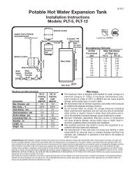
Expansion Tank<br />
When a backflow preventer or no return valve is utilized, a properly sized thermal expansion tank must be installed. This tank is<br />
designed to accept the thermal expansion of stored water as the temperature increases. It maintains safe and proper pressure in the piping<br />
system and prevents unneccessary and nuisance cycling of the T&P valve. Refer to sizing chart for proper selection.<br />
Mixing<br />
Valve<br />
Installation<br />
Thermal Expansion Tank Installation
H2Pro Indirect Fired <strong>Water</strong> Heater<br />
Controls<br />
Install the control element into the well on the tank and tighten in place with the screws on the control body. Thermal paste is recommended,<br />
but is not required or provided.<br />
H2Pro Indirect Fired <strong>Water</strong> Heater<br />
Wiring<br />
All wiring is to be done in accordance with all applicable local, state and national electrical codes.<br />
This work must be done by a licenced professional.<br />
Turn off all power to the boiler before beginning wiring procedures. Refer to wiring diagrams for proper wiring. It is recommended<br />
that a disconnect switch be installed between the boiler control and the water heater.<br />
H2Pro Indirect Fired <strong>Water</strong> Heater<br />
Circulator Sizing<br />
In order to achieve published capacity ratings, the tank circulator must be capable of delivering the required<br />
flow rate AND overcome the resistance in the system piping and tank coil. The pressure drop chart below<br />
includes the piping run and indirect water heater only. The pressure drop from flow checks and zone valves<br />
must be added to the values listed to determine final circulator sizing.<br />
Piping Run Length<br />
GPM 20’ 30’ 40’ 50’ 60’<br />
6 8.6’ 8.9’ 9.2’ 9.5’ 9.8’<br />
8 11.3’ 11.8’ 12.3’ 12.7’ 13.1’<br />
10 10.3’ 11.1’ 12.0’ 12.8’ 13.7’<br />
12 11.3’ 13.2’ 14.1’ 15.0’ 16.0’<br />
14 15.3’ 16.4’ 17.5’ 18.6’ 19.8’<br />
Chart at left represents<br />
the pressure drop<br />
through the specified<br />
length of 1” copper<br />
tubing PLUS (6) 90<br />
degree elbows and (1)<br />
tee on the run.<br />
H2Pro Indirect Fired <strong>Water</strong> Heater<br />
Wiring Diagrams<br />
Zone Valves<br />
Circulator<br />
Please consult the factory for additional wiring diagrams.
H2Pro Indirect Fired <strong>Water</strong> Heater<br />
Troubleshooting<br />
Make sure the power supply is turned off when servicing the <strong>SSI</strong> <strong>Series</strong> Indirect Fired <strong>Water</strong> Heater.<br />
If draining the tank of water, be sure to open a hot water tap in the system to prevent vacuum build<br />
up in the tank.<br />
PROBLEM PO<strong>SSI</strong>BLE CAUSES PO<strong>SSI</strong>BLE SOLUTIONS<br />
NO HOT WATER<br />
Zone Valve not opening<br />
Open manually to check, replace if<br />
neccessary<br />
Circulator not operating<br />
Check operation and replace if neccessary<br />
Tank Control too low<br />
Raise tank temperature (**see note below)<br />
Boiler control too low<br />
Refer to page 2 for proper setting of boiler<br />
control<br />
Wiring incorrect<br />
Refer to wiring diagram<br />
Tank control failure<br />
Replace control<br />
Air trapped in piping<br />
Purge air to remove<br />
NOT ENOUGH HOT WATER<br />
Supply piping undersized<br />
Circulator arrow reversed<br />
Tank temperature too low<br />
Boiler temperature too low<br />
Boiler too small<br />
Demand flow rate too high<br />
Circulator too small<br />
T&P VALVE DISCHARGES<br />
Tank temperature too high<br />
Thermal expansion<br />
<strong>Water</strong> pressure too high<br />
Boiler feed and return should be a minimum<br />
` of 1`”<br />
Reverse flow<br />
Raise setting (**see note below)<br />
Refer to page 2 for proper setting of boiler<br />
control<br />
Refer to page 2 for minimum sizing<br />
requirements<br />
Refer to page 2 for flow rates.<br />
Install mixing valve and raise tank temperature (**see<br />
note below)<br />
Install flow regulator<br />
Add storage capacity<br />
Replace<br />
Lower temperature on tank control<br />
Install thermal expansion tank<br />
Install pressure reducing valve<br />
WATER TEMPERATURE OVER 125 o F CAN CAUSE SEVERE BURNS INSTANTLY, OR EVEN<br />
DEATH FROM SCALDS. CHILDREN, DISABLED, AND ELDERLY ARE AT THE HIGHEST<br />
RISK OF BEING SCALDED. REFER TO INSTRUCTION MANUAL FOR PROPER TEMPER-<br />
ATURE SETTINGS FEEL WATER BEFORE BATHING OR SHOWERING. TEMPERATURE<br />
LIMITING VALVES ARE AVAILABLE.<br />
H2Pro Indirect Fired <strong>Water</strong> Heater<br />
The <strong>SSI</strong> <strong>Series</strong> Indirect should be inspected annually by a qualified professional. Check controls, piping, wiring and operation of the<br />
T&P valve. Tank may be drained to remove any accumulated debris. Refer to these instructions for proper procedures.<br />
Service Record<br />
Date Serviced by Maintenance performed<br />
Maintenance<br />
300 Pond St<br />
Randolph, MA 02368<br />
www.flexconind.com