
Create successful ePaper yourself
Turn your PDF publications into a flip-book with our unique Google optimized e-Paper software.
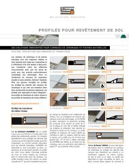
<strong>FLOOR</strong> <strong>DRAINS</strong><br />
INNOVATIVE SOLUTIONS FOR CERAMIC AND STONE TILE<br />
<strong>FLOOR</strong> <strong>DRAINS</strong> FOR BONDED WATERPROOF MEMBRANES<br />
<strong>Schluter</strong> ® -KERDI-DRAIN and<br />
<strong>Schluter</strong> ® -KERDI-LINE floor drains<br />
provide a simple and secure connection<br />
to bonded waterproof membranes at the<br />
top of the assembly via an integrated<br />
bonding flange. Thus, the membrane is<br />
applied entirely at the surface, with all<br />
water directed into the top of the drain.<br />
Application and Function<br />
<strong>Schluter</strong> ® -KERDI-DRAIN and<br />
<strong>Schluter</strong> ® -KERDI-LINE are specifically<br />
designed for use in bonded waterproofing<br />
assemblies, such as showers, steam rooms,<br />
wet rooms, bathroom floors, commercial<br />
kitchen floors and other applications that<br />
require waterproofing and drainage.<br />
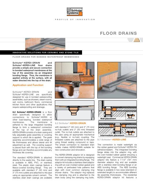
8.2 <strong>Schluter</strong> ® -KERDI-DRAIN is a floor<br />
drain specifically designed to allow<br />
connections to <strong>Schluter</strong> ® -KERDI or<br />
other load-bearing, bonded waterproof<br />
membranes. The membrane is<br />
adhered to the large integrated bonding<br />
flange to form a waterproof connection<br />
at the top of the drain assembly.<br />
KERDI-DRAIN consists of a drain casing and<br />
fully adjustable grate assembly or covering<br />
support to which tile is applied. The grate<br />
assembly accommodates a wide range of<br />
tile thicknesses and allows lateral and tilt<br />
adjustment as well. The covering support<br />
is placed flush with the top of the bonding<br />
flange and can therefore accommodate any<br />
thickness tile covering.<br />
The standard KERDI-DRAIN is attached<br />
directly to the waste line. The drain casing<br />
is available in ABS, PVC, or stainless<br />
steel. The plastic drain casings feature a<br />
fleece-covered bonding flange. They are<br />
available with standard 2" (50 mm) and<br />
3" (75 mm) outlets and attached to the pipe<br />
using an appropriate solvent cement. The<br />
stainless steel drain casings are available<br />
8.2 <strong>Schluter</strong> ® -KERDI-DRAIN<br />
with standard 2" (50 mm) and 3" (75 mm)<br />
no-hub outlets and 2" (50 mm) threaded<br />
outlet. The no-hub outlets are attached to<br />
the pipe using an appropriate mechanical<br />
(e.g., flexible or no-hub) coupling. The<br />
threaded outlets are attached to the pipe<br />
using thread sealing compound or tape.<br />
The simple connection to standard drain<br />
outlets makes KERDI-DRAIN suitable for<br />
new construction and renovation.<br />
The KERDI-DRAIN adaptor kit is designed<br />
to convert clamping ring drains by equipping<br />
them with an integrated bonding flange. The<br />
adaptor kit includes a stainless steel adaptor<br />
ring with an over-molded rubber gasket and<br />
a variety of perforated hole patterns that<br />
align with most common clamping ring<br />
shower drains. The adaptor ring replaces<br />
the clamping ring and is attached to the<br />
drain body using the clamping ring bolts.<br />
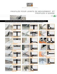
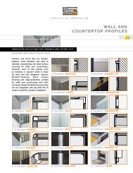
Wall placement<br />
Intermediate placement<br />
8.7 <strong>Schluter</strong> ® -KERDI-LINE<br />
7/8" - 2-1/4" -<br />
22 mm 57 mm<br />
7/8" -<br />
22 mm<br />
4-23/32" - 120 mm<br />
7/8" - 2-1/4" -<br />
22 mm 57 mm<br />
7/8" -<br />
22 mm<br />
5-15/32" - 137 mm<br />
This connection is made watertight via<br />
the rubber gasket and <strong>Schluter</strong> ® -KERDI-FIX<br />
adhesive/sealant. The integrated bonding<br />
flange slides into the adaptor ring, with<br />
the over-molded rubber gasket ensuring a<br />
watertight seal. Commercial KERDI-DRAIN<br />
adaptor kits feature a 7-1/2" (191 mm)<br />
diameter adaptor ring and are available<br />
with a stainless steel bonding flange or an<br />
ABS bonding flange. The ABS bonding<br />
flange is available in two sizes (standard or<br />
extended length) to accommodate different<br />
tile assembly thicknesses. The residential<br />
KERDI-DRAIN adaptor kit features a<br />
15/16" - 24 mm<br />
15/16" - 24 mm
<strong>FLOOR</strong> <strong>DRAINS</strong><br />
5-1/4" (133 mm) diameter adaptor ring<br />
and an ABS bonding flange. The KERDI-<br />
DRAIN adaptor kit is particularly useful in<br />
renovations where the clamping ring drains<br />
are difficult to replace with the standard<br />
KERDI-DRAIN (e.g., when they are set in<br />
concrete slabs).<br />
The grate assembly consists of a height<br />
adjustment collar, lateral adjustment ring,<br />
and drain grate or covering support. The<br />
grates are installed in conjunction with<br />
a height adjustment collar and lateral<br />
adjustment ring, which are made of ABS<br />
or stainless steel, to allow for simple and<br />
convenient adjustment when setting the tile.<br />
Drain grates are available in stainless steel<br />
with a polished or oil-rubbed bronze finish<br />
and in anodized aluminum with a brushed<br />
copper bronze, brushed brass, or brushed<br />
nickel finish. The polished stainless steel<br />
grates are available in 4" (100 mm) -square,<br />
6" (150 mm) -square and -round versions.<br />
All other grates are available in the<br />
4" (100 mm) -square version only. Please<br />
note that grate assemblies included<br />
with the plastic KERDI-DRAIN featuring<br />
3" (75 mm) outlets and the residential<br />
adaptor kits only allow vertical and tilt<br />
adjustment (no lateral adjustment). The<br />
covering support is a 4" (100 mm) -square<br />
stainless steel plate with KERDI laminated<br />
on the surface to allow for bonding of<br />
ceramic or stone tile, which creates a<br />
virtually invisible drainage line.<br />
8.7 <strong>Schluter</strong> ® -KERDI-LINE is a low profile<br />
linear floor drain specifically designed for<br />
bonded waterproofing assemblies. KERDI-<br />
LINE can be installed adjacent to walls or<br />
at intermediate locations. The floor can<br />
be sloped on a single plane to KERDI-<br />
LINE, which enables the use of largeformat<br />
tiles and creates interesting design<br />
opportunities.<br />
KERDI-LINE consists of a formed stainless<br />
steel channel body and grate assembly or<br />
covering support to which tile is applied.<br />
The channel body features a standard<br />
2" (50 mm) no-hub outlet and is attached<br />
to the pipe using an appropriate mechanical<br />
no-hub coupling. The simple connection<br />
to standard drain outlets makes KERDI-<br />
LINE suitable for new construction and<br />
renovation. KERDI-LINE is available with<br />
both center and off-set outlets. The offset<br />
outlet is located 8" (20.3 cm) from the<br />
edge of the channel body and provides<br />
flexibility when obstacles (e.g., floor joists)<br />
are encountered during installation. The<br />
grate assembly can be seamlessly adjusted<br />
2<br />
to the thickness of the ceramic tile or stone<br />
covering from 1/8" to 1" (3 to 25 mm). The<br />
covering support is placed flush with the<br />
top of the channel body and can therefore<br />
accommodate any thickness tile covering.<br />
KERDI-LINE includes a corresponding<br />
polystyrene foam channel support. The<br />
perimeter of the channel body consists of a<br />
bonding flange laminated with a collar made<br />
of KERDI. It ensures a simple and secure<br />
connection to the bonded waterproofing<br />
assembly, both in the floor area and on<br />
adjacent walls.<br />
The grate assembly consists of a brushed<br />
stainless steel frame and two design grate<br />
options. Option A is a closed-design,<br />
brushed stainless steel grate. Option B<br />
is a brushed stainless grate with square<br />
perforations. Option B is also available<br />
with a locking mechanism (3/4" - 19 mm<br />
frame only) for applications where tamper<br />
resistance is desired or required (e.g.,<br />
healthcare and education facilities, etc.).<br />
The covering support D is a stainless steel<br />
plate with KERDI laminated on the surface<br />
to allow for bonding of ceramic or stone tile,<br />
which creates a virtually invisible drainage<br />
line. KERDI-LINE is available in channel<br />
lengths from 20" to 72" (50 to 180 cm) in<br />
4" (10 cm) increments. Please note that<br />
the bonding flange extends approximately<br />
1" (2.5 cm) beyond the channel on all sides.<br />
<strong>Schluter</strong> ® -KERDI-LINE-FC is a stainless<br />
steel cover plate for use with KERDI-LINE<br />
to create a seamless look in applications<br />
where multiple drains are installed end-toend.<br />
KERDI-LINE-FC features a brushed<br />
finish, and is designed for use with either<br />
the solid or perforated grates with brushed<br />
stainless steel frame.<br />
Material Properties and<br />
Areas of Application<br />
KERDI-DRAIN drain casings are formed<br />
using ABS, PVC, or stainless steel 304<br />
(1.4301 = V2A). Plastic drain casings<br />
feature a polypropylene fleece webbing. The<br />
KERDI-DRAIN adaptor kits feature adaptor<br />
rings made of stainless steel 304 (1.4301<br />
= V2A) with thermoplastic rubber gaskets<br />
and adaptor flanges made of stainless<br />
steel 304 (1.4301 = V2A) or ABS. Drain<br />
grates are available in stainless steel 304<br />
(1.4301 = V2A) and anodized aluminum.<br />
The covering support is stainless steel 304<br />
(1.4301 = V2A) with KERDI laminated on<br />
the surface.<br />
The KERDI-LINE channel body is formed<br />
using stainless steel 316 L (1.4404 = V4A)<br />
and features a bonding flange with a KERDI<br />
collar laminated on the surface. KERDI is<br />
a bonded waterproof membrane made<br />
of soft polyethylene, which is covered on<br />
both sides with a special fleece webbing<br />
to anchor the membrane in the thin-set<br />
mortar. The frame and grates are made<br />
of stainless steel 316 L (1.4404 = V4A).<br />
The channel support is made of pressureresistant,<br />
expanded polystyrene (EPS).<br />
KERDI-DRAIN and KERDI-LINE are suitable<br />
for use in residential and commercial<br />
applications, including areas subject to foot<br />
and wheelchair traffic, such as showers<br />
and wet rooms in homes, hotels, schools,<br />
healthcare facilities, etc.<br />
The KERDI-LINE-FC is roll-formed using<br />
stainless steel 316 L (1.4404 = V4A).<br />
Stainless steel can sustain high mechanical<br />
stresses and is particularly suitable for<br />
applications requiring resistance against<br />
chemicals and acids. However, even<br />
stainless steel is not resistant to all<br />
chemical stresses, and may be affected by<br />
hydrochloric and hydrofluoric acid or certain<br />
chloride and brine concentrations, which<br />
may be present in detergents or swimming<br />
pools. In special cases, the suitability of<br />
the selected floor drainage system must be<br />
verified based on the anticipated chemical,<br />
mechanical, and/or other stresses.<br />
Anodized aluminum retains a uniform<br />
appearance during normal use. The surface,<br />
however, is susceptible to scratching and<br />
wear and may be damaged by grout or<br />
setting material. Therefore, these materials<br />
must be removed immediately.<br />
Various configurations of KERDI-DRAIN<br />
and KERDI-LINE are listed by UPC®, CSA,<br />
NSF and ICC-ES PMG.<br />
Note: Product listings and certifications can<br />
be referenced on page 14.
<strong>FLOOR</strong> <strong>DRAINS</strong><br />
Installation<br />
The installation instructions below represent<br />
the use of KERDI-DRAIN and KERDI-LINE<br />
in floor applications. Installation instructions<br />
for the use of KERDI-DRAIN and KERDI-<br />
LINE in shower applications can be found<br />
in the <strong>Schluter</strong> ® -Shower System Installation<br />
Handbook.<br />
KERDI-DRAIN<br />
Preparation<br />
After locating the correct position, cut a<br />
hole in the substrate for the drain outlet<br />
and coupling to the waste line using the<br />
template provided. Note: Fill in box-outs<br />
in concrete floors with dry-pack mortar.<br />
A pipe coupling or similar can be used<br />
as a form around the waste line. Select<br />
form to accommodate the drain outlet<br />
and mechanical no-hub coupling (when<br />
applicable). Limit the diameter of the hole<br />
to 5" (125 mm) maximum to ensure proper<br />
support of the tile assembly. A larger hole<br />
can lead to lack of support and damage the<br />
tile assembly (e.g., cracked grout around<br />
drain).<br />
Drain installation<br />
Access to plumbing from below<br />
If there is access to the plumbing from<br />
below and the waste line can be connected<br />
after installing KERDI-DRAIN, the drain can<br />
be installed in conjunction with the mortar<br />
bed.<br />
1. Place a ring of loose mortar up to the<br />
inlet hole in the floor and firmly press<br />
the drain into the mortar. The bonding<br />
flange must be fully supported to prevent<br />
damage to the tile assembly (e.g.,<br />
cracked grout around drain). When<br />
installing KERDI-DRAIN over wood<br />
substrates, the minimum thickness of<br />
mortar required at the perimeter of the<br />
bonding flange is 1" (25 mm).<br />
2. The screed is then placed flush with the<br />
top of the bonding flange of the KERDI-<br />
DRAIN. Slope the mortar bed using the<br />
bonding flange and mortar screeds as<br />
guides.<br />
No access to plumbing from below<br />
When there is no access to the plumbing<br />
from below, install the KERDI-DRAIN to the<br />
appropriate height prior to the installation of<br />
the shower base.<br />
1. Begin the drain installation by dry fitting<br />
the components. Measure and cut a<br />
section of pipe to connect the KERDI-<br />
DRAIN to the odor trap below the floor,<br />
using the foam spacers included with<br />
the drain as a spacer. When installing<br />
KERDI-DRAIN over wood substrates, the<br />
minimum thickness of mortar required<br />
at the perimeter of the bonding flange is<br />
1" (25 mm).<br />
2. Prepare the odor trap, cut section of<br />
pipe, and KERDI-DRAIN with cleaner,<br />
primer and ABS or PVC cement per<br />
the solvent cement manufacturer’s<br />
instructions and connect.<br />
3. Pack loose mortar under the drain up<br />
to the inlet hole to ensure solid and<br />
uniform support of the bonding flange.<br />
The screed is then placed flush with the<br />
top of the bonding flange of the KERDI-<br />
DRAIN. Slope the mortar bed using the<br />
bonding flange and mortar screeds as<br />
guides.<br />
Clamping ring drain already installed<br />
If a clamping ring drain is already installed,<br />
the drain must be replaced with KERDI-<br />
DRAIN or converted using the KERDI-<br />
DRAIN adaptor kit.<br />
1. If using the KERDI-DRAIN adaptor kit,<br />
remove the clamping ring from the<br />
installed drain and save the bolts for<br />
installation of the adaptor ring. Align<br />
the bolt pattern of the clamping ring<br />
with the matching punch-outs in the<br />
adaptor ring. Punch the matching<br />
inserts out through the stainless steel<br />
adaptor ring.<br />
2. Apply a continuous 1/4" - 3/8" (6 -<br />
10 mm) bead of KERDI-FIX to the<br />
underside of the adaptor ring. Align<br />
the holes in the adaptor ring with the<br />
bolt holes in the installed drain and<br />
place the adaptor ring on the installed<br />
drain flange. Re-insert and tighten<br />
the bolts using a star pattern. Bolts<br />
are to be finger-tight plus 1/4 turn; do<br />
not overtighten, as this may warp the<br />
adaptor ring and result in leaks.<br />
3. Slide the adaptor flange into the adaptor<br />
ring and ensure full support under the<br />
adaptor flange with mortar. The screed<br />
is then placed flush with the top of the<br />
bonding flange of the KERDI-DRAIN.<br />
Slope the mortar bed using the bonding<br />
flange and mortar screeds as guides.<br />
Note: <strong>Schluter</strong> ® -<strong>Systems</strong> recommends a<br />
leak test be performed on the connection<br />
between the drain and the waste line prior<br />
to continuing with the remainder of the<br />
installation whenever possible.<br />
Connection to waterproofing<br />
membranes<br />
The KERDI or DITRA waterproofing<br />
membranes can be installed over the mortar<br />
bed as soon as it can be walked upon.<br />
KERDI<br />
1. Apply unmodified thin-set mortar to<br />
the bonding flange and surrounding<br />
mortar bed with a 1/4" x 3/16" (6 x<br />
5 mm) V-notched trowel or the<br />
KERDI-TROWEL, which features a<br />
1/8" x 1/8" (3 x 3 mm) square-notched<br />
design. The thin-set mortar must be<br />
mixed to a fairly fluid consistency, but<br />
still able to hold a notch.<br />
Note: When using the stainless steel<br />
bonding flange, the membrane is<br />
bonded to the integrated bonding<br />
flange with KERDI-FIX adhesive/<br />
sealant. The stainless steel bonding<br />
flange must be clean and free of grease<br />
or other contaminants prior to KERDI-<br />
FIX application.<br />
2. Embed KERDI in the bond coat and<br />
work the membrane onto the KERDI-<br />
DRAIN bonding flange and mortar bed<br />
with the flat side of the trowel to ensure<br />
full coverage and remove air pockets.<br />
The membrane is carried to the step in<br />
the bonding flange (template provided).<br />
DITRA or DITRA-XL<br />
1. DITRA or DITRA-XL is installed up to<br />
the outer edge of the KERDI-DRAIN<br />
bonding flange. Apply unmodified<br />
thin-set mortar to the mortar bed<br />
surrounding KERDI-DRAIN with a<br />
1/4" x 3/16" (6 x 5 mm) V-notched<br />
trowel or the DITRA-TROWEL, which<br />
features an 11/64" x 11/64" (4.5 x<br />
4.5 mm) square-notched design. The<br />
thin-set mortar must be mixed to a<br />
fairly fluid consistency, but still able to<br />
hold a notch. Solidly embed the matting<br />
into the bond coat using a float, screed<br />
trowel, or DITRA-ROLLER.<br />
2. DITRA or DITRA-XL is sealed to the<br />
KERDI-DRAIN bonding flange using a<br />
cut section of the KERDI membrane.<br />
Apply unmodified thin-set mortar to<br />
the bonding flange and surrounding<br />
membrane with a 1/4" x 3/16"<br />
(6 x 5 mm) V-notched trowel or the KERDI-<br />
TROWEL, which features a 1/8" x 1/8"<br />
(3 x 3 mm) square-notched design.<br />
3
<strong>FLOOR</strong> <strong>DRAINS</strong><br />
Note: When using the stainless steel<br />
bonding flange, the KERDI is bonded<br />
to the integrated bonding flange with<br />
KERDI-FIX adhesive/sealant. The<br />
stainless steel bonding flange must<br />
be clean and free of grease or other<br />
contaminants prior to KERDI-FIX<br />
application.<br />
3. Embed a 20" x 20" (50 x 50 cm) cut<br />
section of KERDI in the bond coat and<br />
work the membrane onto the KERDI-<br />
DRAIN bonding flange and surrounding<br />
membrane to ensure full coverage<br />
and remove air pockets. The KERDI is<br />
carried to the step in the bonding flange<br />
(template provided) and must overlap<br />
the DITRA or DITRA-XL membrane by<br />
a minimum of 2" (50 mm).<br />
Grate assembly<br />
Grate<br />
1. The grate assembly is installed in<br />
conjunction with the tile. Place the<br />
height adjustment collar inside the<br />
lateral adjustment ring and snap the<br />
grate into place.<br />
Note: For drains with 6" (150 mm)<br />
grates, the height adjustment collar<br />
is integrated with the grate. For the<br />
residential adaptor kit, there is no lateral<br />
adjustment ring.<br />
2. Fill the step in the bonding flange<br />
with unmodified thin-set mortar and<br />
back-butter the underside of the<br />
grate to ensure full support. Press the<br />
assembly into the mortar and install<br />
the surrounding tiles, ensuring full<br />
coverage.<br />
3. Position the grate to match the joint<br />
pattern of the tile covering and press<br />
flush with the tile surface. Remove all<br />
excess setting material.<br />
Note: Protect the visible surface of the<br />
grate from contact with setting and grouting<br />
materials. In particular, anodized aluminum<br />
is sensitive to alkaline materials.<br />
Tileable Covering Support<br />
1. The covering support is installed in<br />
conjunction with the tile. Place the tile<br />
spacer inside the lateral adjustment<br />
ring.<br />
2. Fill the step in the bonding flange with<br />
thin-set mortar and press the assembly<br />
into the mortar. Install the surrounding<br />
tiles up to the tile spacer using<br />
unmodified thin-set mortar, ensuring full<br />
coverage. Set the tile to the integrated<br />
tabs on the lateral adjustment ring,<br />
4<br />
which provide for a flush transition<br />
to the covering support. Remove all<br />
excess setting material. Position the tile<br />
spacer to match the joint pattern of the<br />
tile covering.<br />
3. Apply tile to the top of the covering<br />
support using unmodified thin-set<br />
mortar. The tile is installed flush with all<br />
sides of the covering support to provide<br />
the drainage openings.<br />
4. Once the assembly has been set<br />
and grouted, remove the tile spacer<br />
and insert the tiled covering support<br />
in the lateral adjustment ring.<br />
Note: For acid-resistant coverings,<br />
use an epoxy adhesive to set and grout<br />
the tile.<br />
KERDI-LINE<br />
Preparation<br />
1. Any leveling of the floor must be done<br />
prior to the installation of the channel<br />
body. For installation adjacent to the<br />
wall, the channel body must be aligned<br />
in accordance with the thickness of<br />
the wall covering. For intermediate<br />
installation, use the supplied filling strip<br />
with peel-and-stick adhesive layer to<br />
make the channel support symmetrical.<br />
2. KERDI-LINE can be installed in<br />
conjunction with the provided<br />
channel support as described below<br />
or set in loose mortar. KERDI-LINE<br />
is connected to the waste line with<br />
the appropriate mechanical no-hub<br />
coupling in accordance with the<br />
coupling manufacturer’s instructions.<br />
Channel body installation<br />
Access to plumbing from below<br />
When there is access to the plumbing<br />
from below and the waste line can be<br />
connected after installing KERDI-LINE, the<br />
channel body may be set without making a<br />
connection to the waste line simultaneously.<br />
1. Apply unmodified thin-set mortar to<br />
the substrate where the drain is to<br />
be placed with a notched trowel and<br />
solidly embed the channel support in<br />
the mortar.<br />
2. Apply unmodified thin-set mortar to<br />
the top of the channel support with a<br />
notched trowel and press the channel<br />
body firmly into the mortar, ensuring full<br />
support of the bonding flange. Check<br />
to make sure the KERDI-LINE is level.<br />
No access to plumbing from below<br />
When there is no access to the plumbing<br />
from below, the channel body must be<br />
set and connected to the waste line<br />
simultaneously.<br />
1. Begin the drain installation by dry fitting<br />
the components. Measure and cut a<br />
section of pipe to connect the coupling<br />
to the odor trap below the floor, using<br />
the channel support as a spacer.<br />
2. Apply unmodified thin-set mortar to<br />
the top of the channel support with a<br />
notched trowel and press the channel<br />
support firmly onto the underside of the<br />
channel body. Attach the mechanical<br />
coupling to the drain outlet and the cut<br />
section of the pipe per the coupling<br />
manufacturer’s instructions.<br />
3. Apply unmodified thin-set mortar to<br />
the substrate where the drain is to<br />
be placed with a notched trowel.<br />
Prepare the cut section of pipe and<br />
odor trap with cleaner, primer and ABS<br />
or PVC cement per the solvent cement<br />
manufacturer’s instructions.<br />
4. Solidly embed the channel support and<br />
KERDI-LINE into the mortar on the floor<br />
and connect the cut section of pipe to<br />
the odor trap. Check to make sure the<br />
KERDI-LINE is level.<br />
5. The screed is then placed flush with the<br />
top of the bonding flange of the KERDI-<br />
LINE. Slope the mortar bed using the<br />
bonding flange and mortar screeds as<br />
guides.<br />
Note: KERDI-FIX or other adhesives that<br />
are compatible with EPS foam can be used<br />
to install the channel support and channel<br />
body as an alternative to thin-set mortar.<br />
Apply a generous bead of KERDI-FIX to<br />
the top and bottom of the channel support.<br />
The use of KERDI-FIX limits the ability to<br />
level KERDI-LINE.<br />
Note: <strong>Schluter</strong> ® -<strong>Systems</strong> recommends a<br />
leak test be performed on the connection<br />
between the drain and the waste line prior<br />
to continuing with the remainder of the<br />
installation whenever possible.<br />
Connection to waterproofing<br />
membranes<br />
The KERDI or DITRA waterproofing<br />
membranes can be installed as soon as the<br />
mortar bed can be walked upon.<br />
1. KERDI, DITRA or DITRA-XL is installed<br />
up to the outer edge of the KERDI-LINE<br />
bonding flange using unmodified thinset<br />
mortar. The thin-set mortar must be<br />
mixed to a fairly fluid consistency, but
<strong>FLOOR</strong> <strong>DRAINS</strong><br />
still able to hold a notch.<br />
a. KERDI: Apply unmodified thin-set<br />
mortar to the mortar bed surrounding<br />
KERDI-LINE with a 1/4" x 3/16" (6 x<br />
5 mm) V-notched trowel or the KERDI-<br />
TROWEL, which features a 1/8" x 1/8"<br />
(3 x 3 mm) square-notched design.<br />
Embed KERDI in the bond coat with<br />
the flat side of the trowel to ensure<br />
full coverage and remove air pockets.<br />
b. DITRA: Apply unmodified thin-set<br />
mortar to the mortar bed surrounding<br />
KERDI-LINE with a 1/4" x 3/16" (6 x<br />
5 mm) V-notched trowel or the DITRA-<br />
TROWEL, which features an 11/64" x<br />
11/64" (4.5 x 4.5 mm) square-notched<br />
design. Solidly embed the matting into<br />
the bond coat using a float, screed<br />
trowel, or DITRA-ROLLER.<br />
2. Apply unmodified thin-set mortar to<br />
the membrane surrounding KERDI-<br />
LINE with a 1/4" x 3/16" (6 x<br />
5 mm) V-notched trowel or the KERDI-<br />
TROWEL, which features a 1/8" x 1/8"<br />
(3 x 3 mm) square-notched design.<br />
Embed the KERDI collar in the bond<br />
coat to ensure full coverage and remove<br />
air pockets.<br />
Grate assembly<br />
Grate A and B<br />
1. Apply unmodified thin-set mortar to<br />
the underside of the grate frame and<br />
place it in the channel body ensuring<br />
full coverage and support of the<br />
frame. Insert the foam spacers in the<br />
grate frame to reinforce it during the<br />
remainder of the installation.<br />
Note: The tape on the grate frame does<br />
not need to be removed. It is intended<br />
to help keep setting material out of the<br />
channel body during installation.<br />
2. Insert the plastic height adjustment<br />
spacers with threaded bolts under the<br />
tabs along the inside of the grate frame<br />
to adjust the elevation of the frame<br />
such that the surface of the frame will<br />
be flush with the surface of the tile<br />
covering. The spacers may be adjusted<br />
simply by turning the bolts by hand.<br />
3. Apply unmodified thin-set mortar to the<br />
substrate and install the tiles, ensuring<br />
full coverage. Once the tile covering is<br />
set and grouted, remove the spacers<br />
from the grate frame and insert the<br />
grate.<br />
Note: Protect the visible surfaces of the<br />
grate frame and grate from contact with<br />
setting and grouting materials. Setting<br />
and grouting materials must be removed<br />
immediately.<br />
KERDI-LINE-FC<br />
1. Install KERDI-LINE channel bodies endto-end<br />
and overlap the KERDI collars<br />
using unmodified thin-set mortar to<br />
ensure a waterproof connection.<br />
KERDI-LINE-FC is subsequently<br />
installed in conjunction with the KERDI-<br />
LINE grate assembly and adjacent tiles.<br />
Note: KERDI-LINE-FC may be used<br />
with tiles that are 1/4" (6 mm) thick or<br />
greater.<br />
2. Apply a sufficient amount of thin-set<br />
mortar to the substrate and/or the<br />
back of KERDI-LINE-FC and press the<br />
profile into the mortar until its surface<br />
is flush with the adjacent tile and grate<br />
assembly.<br />
3. Leave a space of approximately 1/16" –<br />
1/8" (1.5 – 3 mm).<br />
4. Fill the joints completely with grout or<br />
setting material.<br />
Grate D<br />
Wall Installation<br />
1. Peel protective foil off the cover strip<br />
and adhere the strip to the bonding<br />
flange adjacent to the wall(s). Position<br />
the strip along the edge of the channel.<br />
The cover strip hides and protects the<br />
KERDI surface under the tile.<br />
2. Insert the tile spacers into the channel<br />
body. Install the surrounding tile on<br />
the adjoining walls and mortar bed<br />
up to the spacers using unmodified<br />
thin-set mortar, ensuring full coverage.<br />
Remove all excess setting material.<br />
3. Apply tile to the top of the covering<br />
support using unmodified thin-set<br />
mortar. The tile is installed flush with<br />
the front side of the covering support<br />
to provide the drainage opening and<br />
overhanging the back side of the<br />
covering support to cover the bonding<br />
flange along the wall. Measure and cut<br />
the tile such that an approximate 1/16"<br />
(1 mm) gap is left at the wall. When the<br />
ends of the channel body are located<br />
adjacent to walls, the tile is installed<br />
overhanging the end of the plate to<br />
cover the bonding flange along the<br />
walls. Measure and cut the tile such<br />
that an approximate 1/16" (1 mm) gap<br />
is left at the walls.<br />
Note: When the mortar bed is tiled beyond<br />
the ends of the channel, the tile on the ends<br />
of the covering support can be cut to either<br />
match the grout joints of the surrounding<br />
floor covering or to provide a perimeter<br />
drainage opening.<br />
Intermediate Installation<br />
1. When the ends of the channel body<br />
are located adjacent to walls, peel<br />
protective foil off the cover strip and<br />
adhere the strip to the bonding flange<br />
adjacent to the walls. Position the<br />
strip along the edge of the channel.<br />
The cover strip hides and protects the<br />
KERDI surface under the tile. When<br />
the mortar bed will be tiled beyond the<br />
ends of the channel, the cover strip is<br />
not required.<br />
2. Insert the tile spacers into the channel<br />
body. Install the surrounding tile on the<br />
adjoining walls (if applicable) and mortar<br />
bed up to the spacers using unmodified<br />
thin-set mortar, ensuring full coverage.<br />
Remove all excess setting material.<br />
3. Apply tile to the top of the covering<br />
support using thin-set mortar. The tile<br />
is installed flush with the front and<br />
back of the covering support to provide<br />
the drainage openings. When the<br />
ends of the channel body are located<br />
adjacent to walls, the tile is installed<br />
overhanging the end of the plate to<br />
cover the bonding flange along the wall.<br />
Measure and cut the tile such that an<br />
approximate 1/16" (1 mm) gap is left at<br />
the wall.<br />
Note: When the mortar bed is tiled beyond<br />
the ends of the channel, the tile on the<br />
ends of the covering support can be cut<br />
to either match the grout joints of the<br />
surrounding floor covering or to provide<br />
perimeter drainage openings.<br />
Note: For acid-resistant coverings, use an<br />
epoxy adhesive to set and grout the tile.<br />
Maintenance<br />
KERDI-DRAIN and KERDI-LINE require no<br />
special maintenance and are resistant to<br />
mold and fungi. The grate may be removed<br />
to clean the drain housing and the drain<br />
pipes.<br />
Clean the grates and profiles using common<br />
household cleaning agents. Stainless steel<br />
exposed to the environment or aggressive<br />
substances should be cleaned periodically<br />
using a mild household cleaner. Regular<br />
cleaning maintains the neat appearance<br />
of stainless steel and reduces the risk of<br />
corrosion. All cleaning agents must be<br />
free of hydrochloric and hydrofluoric acid.<br />
Stainless steel surfaces develop a sheen<br />
when treated with a chrome-polishing<br />
agent. Do not use abrasive or alkaline<br />
cleaning agents.<br />
5
<strong>FLOOR</strong> <strong>DRAINS</strong><br />
Product Item Numbers<br />
8.2 <strong>Schluter</strong> ® -KERDI-DRAIN<br />
4" Grate Options<br />
Tileable Covering Support Anodized Aluminum Stainless Steel<br />
(ECS)<br />
Patent pending<br />
Brushed<br />
nickel<br />
(ATGB)<br />
Brushed<br />
copper/<br />
bronze<br />
(AKGB)<br />
Brushed<br />
brass<br />
(AMGB)<br />
Oil-rubbed<br />
bronze<br />
(EOB)<br />
Stainless<br />
steel (E)<br />
6" Grate Options<br />
Stainless Steel<br />
Stainless Steel Cover for Cleanout Applications<br />
(6E) (6RE) (6CE) (6RCE)<br />
Flange Options<br />
ABS - 2" or 3" Outlet PVC - 2" or 3" Outlet Stainless Steel - 2" or 3"<br />
No-hub Outlet<br />
Stainless Steel - 2"<br />
Threaded Outlet<br />
Note: Product listings and certifications can be referenced on page 14.<br />
6
<strong>FLOOR</strong> <strong>DRAINS</strong><br />
DRAIN KITS - ABS or PVC FLANGE - 2" OR 3" OUTLET<br />
<strong>Schluter</strong> ® -KERDI-DRAIN - Components - ABS or PVC Flange<br />
1<br />
Includes Description Quantity<br />
1<br />
KERDI-DRAIN<br />
Drain with integrated bonding flange and grate<br />
assembly<br />
1<br />
2<br />
KERDI-KERECK-F<br />
Preformed waterproofing corners<br />
4 inside and<br />
2 outside<br />
2<br />
3<br />
4<br />
3<br />
KERDI-SEAL-PS Pipe seal (3/4" - 20 mm) 1<br />
4<br />
KERDI-SEAL-MV Mixing valve seal 1<br />
2" Drain Outlet<br />
3" Drain Outlet<br />
Round grate<br />
stainless steel (6RE)<br />
KD2/ABS/6RE 1 KD2/PVC/6RE 1<br />
ABS flange PVC flange<br />
ABS flange PVC flange<br />
4" (100 mm) Square Grate<br />
6" (150 mm) Square or Round Grate<br />
Tileable covering<br />
support (ECS)*<br />
KD2/ABS/ECS 1 KD2/PVC/ECS 1<br />
Square grate<br />
stainless steel (6E)<br />
KD3/ABS/6E 1 KD3/PVC/6E 1<br />
Stainless steel<br />
(E)<br />
KD2/ABS/E 1 KD2/PVC/E 1<br />
Round grate<br />
stainless steel (6RE)<br />
KD3/ABS/6RE 1 KD3/PVC/6RE 1<br />
Oil-rubbed bronze<br />
stainless steel (EOB)<br />
KD2/ABS/EOB KD2/PVC/EOB<br />
Brushed brass<br />
anod. alu. (AMGB)<br />
KD2/ABS/AMGB 1 KD2/PVC/AMGB 1<br />
Brushed copper/ bronze<br />
anod. alu. (AKGB)<br />
KD2/ABS/AKGB 1 KD2/PVC/AKGB 1<br />
Brushed nickel<br />
anod. alu. (ATGB)<br />
KD2/ABS/ATGB 1 KD2/PVC/ATGB 1<br />
6" (150 mm) Square or Round Grate<br />
Square grate<br />
stainless steel (6E)<br />
KD2/ABS/6E 1 KD2/PVC/6E 1<br />
1<br />
Listed by UPC®, CSA, ICC-ES PMG, and NSF<br />
* Patent pending<br />
Flange Measurements<br />
ABS or PVC<br />
2" (50 mm) drain outlet 3" (75 mm) drain outlet<br />
A 11-13/16" - 300 mm 11-13/16" - 300 mm<br />
B 4-17/32" - 115.2 mm 4-17/32" - 115.2 mm<br />
C 2-45/64" - 68.6 mm 3-15/16" - 100 mm<br />
D 2-3/8" - 60.5 mm 3-1/2" - 88.8 mm<br />
E 3-15/16" - 100 mm 3-15/16" - 100 mm<br />
F 1-39/64" - 40.6 mm 2" - 50.8 mm<br />
G 7/8" - 22.5 mm 1-1/2" - 38.1 mm<br />
7
<strong>FLOOR</strong> <strong>DRAINS</strong><br />
DRAIN KITS - STAINLESS STEEL FLANGE - 2" OR 3" NO-HUB OUTLET<br />
<strong>Schluter</strong> ® -KERDI-DRAIN - Components - Stainless Steel Flange<br />
1<br />
Includes Description Quantity<br />
1<br />
KERDI-DRAIN<br />
Drain with integrated bonding flange and<br />
grate assembly<br />
1<br />
2<br />
KERDI-KERECK-F Preformed waterproofing corners 4 inside and 2 outside<br />
2<br />
3<br />
4<br />
5<br />
3<br />
4<br />
5<br />
KERDI-SEAL-PS Pipe seal (3/4" - 20 mm) 1<br />
KERDI-SEAL-MV Mixing valve seal 1<br />
KERDI-FIX Sealing and bonding compound (66 ml) 1<br />
2" No-hub Outlet<br />
3" No-hub Outlet<br />
Stainless steel<br />
flange<br />
Stainless steel<br />
flange<br />
4" (100 mm) Square Grate<br />
Tileable covering support (ECS)* KD2/E/ECS 1<br />
Stainless steel (E) KD2/E/E 1<br />
6" (150 mm) Square or Round Grate<br />
Square grate stainless steel (6E) KD3/E/6E 1<br />
Round grate stainless steel (6RE) KD3/E/6RE 1<br />
Oil-rubbed bronze stainless steel (EOB)<br />
KD2/E/EOB<br />
Brushed brass anod. alu. (AMGB) KD2/E/AMGB 1<br />
Brushed copper/ bronze anod. alu. (AKGB) KD2/E/AKGB 1<br />
Brushed nickel anod. alu. (ATGB) KD2/E/ATGB 1<br />
6" (150 mm) Square or Round Grate<br />
Square grate stainless steel (6E) KD2/E/6E 1<br />
Round grate stainless steel (6RE) KD2/E/6RE 1<br />
1<br />
Listed by UPC®, CSA, ICC-ES PMG, and NSF<br />
* Patent pending<br />
Flange Measurements<br />
Stainless steel<br />
2" (50 mm) no-hub outlet 3" (75 mm) no-hub outlet<br />
A 9-27/32" - 250 mm 9-27/32" - 250 mm<br />
B 4-1/2" - 115.4 mm 4-1/2" - 114 mm<br />
C 2-13/32" - 61.3 mm 3-7/16" - 87.4 mm<br />
D 2-13/32" - 60.6 mm 3-5/16" - 84.2 mm<br />
E 3-11/32" - 85 mm 3-7/16" - 87.4 mm<br />
F 53/64" - 21 mm 1-5/32" - 29.4 mm<br />
8
<strong>FLOOR</strong> <strong>DRAINS</strong><br />
GRATE & FLANGE KITS (sold separately)<br />
Grate Kit - Components<br />
Flange Kit - Components<br />
1a<br />
1b<br />
Patent pending<br />
2<br />
3<br />
4<br />
Includes<br />
Quantity<br />
Drain with integrated bonding flange 1<br />
Includes Description Quantity<br />
1a 1b Grate Assembly<br />
2 KERDI-KERECK-F<br />
a) For stainless steel and aluminum grates<br />
b) For tileable covering support<br />
Preformed waterproofing corners<br />
1<br />
4 inside and<br />
2 outside<br />
3 KERDI-SEAL-PS Pipe seal (3/4" - 20 mm) 1<br />
4 KERDI-SEAL-MV Mixing valve seal 1<br />
Flange Kits<br />
Material<br />
2" (50 mm) Drain Outlet<br />
ABS<br />
Item No.<br />
KD2/ABS/FL<br />
Grate Kits<br />
Finish<br />
4" (100 mm) Square Grate<br />
Tileable covering support (ECS)*<br />
Stainless steel (E)<br />
Oil-rubbed bronze stainless steel (EOB)<br />
Brushed brass anod. alu. (AMGB)<br />
Brushed copper/ bronze anod. alu. (AKGB)<br />
Brushed nickel anod. alu. (ATGB)<br />
6" (150 mm) Square or Round Grate<br />
Square grate stainless steel (6E)<br />
Round grate stainless steel (6RE)<br />
6" (150 mm) Square or Round Cover<br />
Square cover stainless steel (6CE)<br />
Round cover stainless steel (6RCE)<br />
Item No.<br />
KD2/ECS/GR<br />
KD2/E/GR<br />
KD2/EOB/GR<br />
KD2/AMGB/GR<br />
KD2/AKGB/GR<br />
KD2/ATGB/GR<br />
KD2/6E/GR<br />
KD2/6RE/GR<br />
KD-GR6C-E<br />
KD-GR6RC-E<br />
PVC<br />
Stainless Steel<br />
with no-hub outlet<br />
Stainless Steel<br />
with threaded outlet<br />
3" (75 mm) Drain Outlet<br />
ABS<br />
PVC<br />
Stainless Steel<br />
with no-hub outlet<br />
i<br />
KD2/PVC/FL<br />
KD2/E/FL<br />
KD2/ETH/FL<br />
KD3/ABS/FL<br />
KD3/PVC/FL<br />
KD3/E/FL<br />
Please note that flanges with 3" outlets are intended for<br />
use with 6" grates as these combinations have listings and<br />
certifications while flanges with 3" outlet combined with 4"<br />
grates do not. Please refer to the Listings and Certifications<br />
table on page 14.<br />
Note: 6" square and round covers do not include the seals and corners.<br />
* Patent pending<br />
9
<strong>FLOOR</strong> <strong>DRAINS</strong><br />
DRAIN ADAPTOR KIT FOR USE WITH RESIDENTIAL CLAMPING RING <strong>DRAINS</strong> - ABS<br />
<strong>Schluter</strong> ® -KERDI-DRAIN with residential adaptor ring and ABS flange<br />
1<br />
Includes Description Quantity<br />
2<br />
1<br />
2<br />
3<br />
KERDI-DRAIN<br />
Drain with integrated bonding flange and<br />
grate assembly<br />
Adaptor ring* For residential clamping ring drains 1<br />
KERDI-KERECK-F Preformed waterproofing corners 4 inside and 2 outside<br />
1<br />
3<br />
4<br />
5<br />
4<br />
KERDI-SEAL-PS Pipe seal (3/4" - 20 mm) 1<br />
5<br />
KERDI-SEAL-MV Mixing valve seal 1<br />
6 KERDI-FIX Sealing and bonding compound (66 ml) 1<br />
* D <strong>Schluter</strong>-<strong>Systems</strong> L.P., U.S. patent No. D593,641, other patents pending<br />
Residential Adaptor Kits - ABS Flange<br />
ABS bonding flange<br />
4" (100 mm) Square Grate<br />
Stainless steel (E)<br />
Oil-rubbed bronze stainless steel (EOB)<br />
Brushed brass anod. alu. (AMGB)<br />
Brushed copper/ bronze anod. alu. (AKGB)<br />
Brushed nickel anod. alu. (ATGB)<br />
KDAR/ABS/E<br />
KDAR/ABS/EOB<br />
KDAR/ABS/AMGB<br />
KDAR/ABS/AKGB<br />
KDAR/ABS/ATGB<br />
Flange and adaptor ring measurements - Residential<br />
ABS<br />
Standard<br />
A<br />
11-13/16" - 300 mm<br />
B 2-13/32" - 60.7 mm<br />
C 2.73" - 69.3 mm<br />
D 5-1/4" - 133.4 mm<br />
E 2-29/32" - 74 mm<br />
F 1-1/64" - 25.9 mm<br />
G 2-1/16" - 52.6 mm<br />
10
<strong>FLOOR</strong> <strong>DRAINS</strong><br />
DRAIN ADAPTOR KIT FOR USE WITH COMMERCIAL CLAMPING RING <strong>DRAINS</strong> - ABS<br />
<strong>Schluter</strong> ® -KERDI-DRAIN with commercial adaptor ring and ABS flange<br />
1<br />
Includes Description Quantity<br />
2<br />
1<br />
KERDI-DRAIN<br />
Drain with integrated bonding flange and grate<br />
assembly<br />
2<br />
Adaptor ring*<br />
For commercial clamping ring drains<br />
1<br />
3<br />
3<br />
KERDI-FIX<br />
Sealing and bonding compound (66 ml)<br />
* D <strong>Schluter</strong>-<strong>Systems</strong> L.P., U.S. patent No. D593,641, other patents pending<br />
Commercial Adaptor Kits - ABS Flange<br />
4" (100 mm) Square Grate<br />
Standard ABS<br />
bonding flange<br />
Extended ABS<br />
bonding flange<br />
Tileable covering support (ECS)* KDA/ABS/ECS KDA/ABSL/ECS<br />
Stainless steel (E) KDA/ABS/E KDA/ABSL/E<br />
Oil-rubbed bronze stainless steel (EOB) KDA/ABS/EOB KDA/ABSL/EOB<br />
Brushed brass anod. alu. (AMGB) KDA/ABS/AMGB KDA/ABSL/AMGB<br />
Brushed copper/ bronze anod. alu. (AKGB) KDA/ABS/AKGB KDA/ABSL/AKGB<br />
Brushed nickel anod. alu. (ATGB) KDA/ABS/ATGB KDA/ABSL/ATGB<br />
6" (150 mm) Square or Round Grate<br />
* Patent pending<br />
Square grate stainless steel (6E) KDA/ABS/6E KDA/ABSL/6E<br />
Round grate stainless steel (6RE) KDA/ABS/6RE KDA/ABSL/6RE<br />
Flange and adaptor ring measurements - Commercial<br />
ABS<br />
Standard<br />
Extended<br />
A 11-13/16" - 300 mm 11-13/16" - 300 mm<br />
B 4-13/32" - 111.8 mm 4-13/32" - 111.8 mm<br />
C 4-11/16" - 118.9 mm 4-11/16" - 118.9 mm<br />
D 7-1/2" - 191 mm 7-1/2" - 191 mm<br />
E 5-7/64" - 130 mm 5-7/64" - 130 mm<br />
F 1-9/16" - 39.7 mm 3-1/16" - 77.8 mm<br />
G 2-9/64" - 54.3 mm 3-41/64" - 92.4 mm<br />
11
<strong>FLOOR</strong> <strong>DRAINS</strong><br />
DRAIN ADAPTOR KIT FOR USE WITH COMMERCIAL CLAMPING RING <strong>DRAINS</strong> - STAINLESS STEEL<br />
<strong>Schluter</strong> ® -KERDI-DRAIN with commercial adaptor ring and stainless steel flange<br />
1<br />
Includes Description Quantity<br />
2<br />
1<br />
KERDI-DRAIN<br />
Drain with integrated bonding flange and<br />
grate assembly<br />
2<br />
Adaptor ring*<br />
For commercial clamping ring drains<br />
1<br />
3<br />
3<br />
KERDI-FIX<br />
Sealing and bonding compound (66 ml)<br />
* D <strong>Schluter</strong>-<strong>Systems</strong> L.P., U.S. patent No. D593,641, other patents pending<br />
Commercial Adaptor Kits - Stainless Steel Flange<br />
4" (100 mm) Square Grate<br />
Stainless steel<br />
bonding flange<br />
Tileable covering support (ECS)*<br />
Stainless steel (E)<br />
Oil-rubbed bronze stainless steel (EOB)<br />
Brushed brass anod. alu. (AMGB)<br />
Brushed copper/ bronze anod. alu. (AKGB)<br />
Brushed nickel anod. alu. (ATGB)<br />
KDA/E/ECS<br />
KDA/E/E<br />
KDA/E/EOB<br />
KDA/E/AMGB<br />
KDA/E/AKGB<br />
KDA/E/ATGB<br />
6" (150 mm) Square or Round Grate<br />
Square grate stainless steel (6E)<br />
Round grate stainless steel (6RE)<br />
KDA/E/6E<br />
KDA/E/6RE<br />
* Patent pending<br />
Flange and adaptor ring measurements - Commercial<br />
Stainless steel<br />
Standard<br />
A 9-27/32" - 250 mm<br />
B 4-9/16" - 115.7 mm<br />
C 4-11/16" - 118.7 mm<br />
D 7-1/2" - 191 mm<br />
E 5-7/64" - 130 mm<br />
F 1-9/16" - 39.7 mm<br />
G 2-3/16" - 56.5 mm<br />
Product Listings and Certifications Table<br />
<strong>Schluter</strong> ® -KERDI-DRAIN - Listings and Certifications<br />
12<br />
Bonding Flange 2" (50 mm) Outlet<br />
Grate - 4" (100 mm)<br />
Grate - 6" (150 mm)<br />
E EOB AMGB AKGB ATGB ECS* 6E 6RE 6CE 6RCE<br />
ABS / PVC 1 - 1 1 1 1 1 1 2 2<br />
Stainless steel 1 - 1 1 1 1 1 1 2 2<br />
Bonding Flange 3" (75 mm) Outlet<br />
Grate - 6" (150 mm)<br />
6E 6RE 6CE 6RCE<br />
ABS / PVC 1 1 2 2<br />
Stainless steel 1 1 2 2<br />
Various configurations of KERDI-DRAIN are listed by ICC-ES (Report No. PMG-1204), UPC®, CSA, and NSF<br />
1 - Listed by ICC-ES (Report No. PMG-1204), UPC®, CSA, and NSF<br />
2 - Listed by CSA<br />
* Patent pending
<strong>FLOOR</strong> <strong>DRAINS</strong><br />
Note: There are multiple selections to be made for this product. Start by selecting the appropriate flange length then<br />
proceed to grate selection accordingly, keeping in mind there are two frame heights with two grate options (A or B),<br />
and a frameless option (D).<br />
8" - 20.3 cm<br />
= L<br />
= L1<br />
= L<br />
= L1<br />
8.7 <strong>Schluter</strong> ® -KERDI-LINE Bonding flange - stainless steel - center outlet<br />
L =<br />
in. - cm<br />
L 1 =<br />
in. - cm<br />
Item No.<br />
20 - 50 22 - 55 KLV 60 E 50<br />
24 - 60 26 - 65 KLV 60 E 60<br />
28 - 70 30 - 75 KLV 60 E 70<br />
32 - 80 34 - 85 KLV 60 E 80<br />
36 - 90 38 - 95 KLV 60 E 90<br />
40 - 100 42 - 105 KLV 60 E 100<br />
44 - 110 46 - 115 KLV 60 E 110<br />
48 - 120 50 - 125 KLV 60 E 120<br />
52 - 130 54 - 135 KLV 60 E 130<br />
56 - 140 58 - 145 KLV 60 E 140<br />
60 - 150 62 - 155 KLV 60 E 150<br />
64 - 160 66 - 165 KLV 60 E 160<br />
68 - 170 70 - 175 KLV 60 E 170<br />
72 - 180 74 - 185 KLV 60 E 180<br />
8.7 <strong>Schluter</strong> ® -KERDI-LINE Bonding flange - stainless steel - off-center outlet<br />
L =<br />
in. - cm<br />
L 1 =<br />
in. - cm<br />
Item No.<br />
28 - 70 30 - 75 KLVO 60 E 70<br />
32 - 80 34 - 85 KLVO 60 E 80<br />
36 - 90 38 - 95 KLVO 60 E 90<br />
40 - 100 42 - 105 KLVO 60 E 100<br />
44 - 110 46 - 115 KLVO 60 E 110<br />
48 - 120 50 - 125 KLVO 60 E 120<br />
Note : Please see page 14 for listings and certifications.<br />
14.1 <strong>Schluter</strong> ® -KERDI-LINE-FC Cover plate<br />
Item No.<br />
Width<br />
V / KLEB 35<br />
1-3/8" - 35 mm<br />
35 mm - 1-3/8''<br />
13
<strong>FLOOR</strong> <strong>DRAINS</strong><br />
3/8" -<br />
10 mm<br />
1-27/32" -<br />
47 mm<br />
8.7 <strong>Schluter</strong> ® -KERDI-LINE Grate assemblies<br />
Length =<br />
in. - cm<br />
Item No.<br />
Item No.<br />
Closed (A) Perforated (B) Frameless Tileable (D) - Patent pending<br />
Closed (A)<br />
Perforated (B)<br />
2-29/32" - 74 mm<br />
2-1/8" - 54 mm<br />
3/8" -<br />
10 mm<br />
2-29/32" - 74 mm<br />
2" - 50 mm<br />
= H<br />
= H<br />
3/4" - 19 mm frame height for 1/8" to 9/16" -<br />
3 mm to 15 mm -thick coverings<br />
Center outlet<br />
Off-set outlet<br />
20 - 50 KLAR 19 EB 50 KLB 19 EB 50 KLDRE 50 -<br />
24 - 60 KLAR 19 EB 60 KLB 19 EB 60 KLDRE 60 -<br />
28 - 70 KLAR 19 EB 70 KLB 19 EB 70 KLDRE 70 KLDRO E 70<br />
32 - 80 KLAR 19 EB 80 KLB 19 EB 80 KLDRE 80 KLDRO E 80<br />
36 - 90 KLAR 19 EB 90 KLB 19 EB 90 KLDRE 90 KLDRO E 90<br />
40 - 100 KLAR 19 EB 100 KLB 19 EB 100 KLDRE 100 KLDRO E 100<br />
44 - 110 KLAR 19 EB 110 KLB 19 EB 110 KLDRE 110 KLDRO E 110<br />
48 - 120 KLAR 19 EB 120 KLB 19 EB 120 KLDRE 120 KLDRO E 120<br />
52 - 130 KLAR 19 EB 130 KLB 19 EB 130 KLDRE 130 -<br />
56 - 140 KLAR 19 EB 140 KLB 19 EB 140 KLDRE 140 -<br />
60 - 150 KLAR 19 EB 150 KLB 19 EB 150 KLDRE 150 -<br />
64 - 160 KLAR 19 EB 160 KLB 19 EB 160 KLDRE 160 -<br />
68 - 170 KLAR 19 EB 170 KLB 19 EB 170 KLDRE 170 -<br />
72 - 180 KLAR 19 EB 180 KLB 19 EB 180 KLDRE 180 -<br />
Frameless Tileable (D)<br />
Patent pending<br />
1-1/8" - 30 mm frame height for 1/2" to 1" -<br />
13 mm to 25 mm -thick coverings<br />
20 - 50 KLAR 30 EB 50 KLB 30 EB 50<br />
24 - 60 KLAR 30 EB 60 KLB 30 EB 60<br />
28 - 70 KLAR 30 EB 70 KLB 30 EB 70<br />
32 - 80 KLAR 30 EB 80 KLB 30 EB 80<br />
36 - 90 KLAR 30 EB 90 KLB 30 EB 90<br />
40 - 100 KLAR 30 EB 100 KLB 30 EB 100<br />
44 - 110 KLAR 30 EB 110 KLB 30 EB 110<br />
48 - 120 KLAR 30 EB 120 KLB 30 EB 120<br />
Note: The perforated grate (B) is also available with a locking mechanism to prevent removal of the grate.<br />
For more information contact customer service at 1-800-472-4588 (US) or 1-800-667-8746 (CANADA).<br />
Product Listings and Certifications Table<br />
<strong>Schluter</strong> ® -KERDI-DRAIN<br />
Bonding Flange 2" (50 mm) Outlet<br />
Grate - 4" (100 mm)<br />
Grate - 6" (150 mm)<br />
E EOB AMGB AKGB ATGB ECS* 6E 6RE 6CE 6RCE<br />
ABS / PVC 1 - 1 1 1 1 1 1 2 2<br />
Stainless steel 1 - 1 1 1 1 1 1 2 2<br />
Bonding Flange 3" (75 mm) Outlet<br />
<strong>Schluter</strong> ® -KERDI-LINE<br />
Grate - 6" (150 mm)<br />
6E 6RE 6CE 6RCE<br />
ABS / PVC 1 1 2 2<br />
Stainless steel 1 1 2 2<br />
Bonding Flange<br />
Grate<br />
A B D*<br />
Center outlet - 20" - 48" (50 cm - 120 cm) 1 1 1<br />
Center outlet - 52" - 72" (130 cm - 180 cm) 1 1 1<br />
Off-set outlet - 28" - 48" (70 cm - 120 cm) 1 1 1<br />
Various configurations of KERDI-DRAIN and KERDI-LINE are listed by UPC®, CSA, ICC-ES PMG, and NSF as shown in the table above.<br />
1 - Listed by UPC®, CSA, NSF, and ICC-ES PMG<br />
2 - Listed by CSA<br />
* Patent pending<br />
For copies of these documents, please contact <strong>Schluter</strong> ® -<strong>Systems</strong> at 800-472-4588 (USA) or 800-667-8746 (Canada) or by email at info@schluter.com. Links to the documents can also be accessed at www.schluter.com.<br />
14
<strong>FLOOR</strong> <strong>DRAINS</strong><br />
<strong>Schluter</strong> ® -<strong>Systems</strong> Floor Drains 10-Year Limited Warranty<br />
COVERAGE AND CONDITIONS: Subject to the conditions and limitations as stated hereinafter, <strong>Schluter</strong> <strong>Systems</strong>* warrants that<br />
<strong>Schluter</strong> ® -KERDI-DRAIN or <strong>Schluter</strong> ® -KERDI-LINE (the “Product”) will be free from manufacturing defects, and will not rot, deteriorate or break down<br />
under normal use for a period of ten (10) years from the date of purchase only when the Product is used and installed in accordance with the terms and<br />
conditions of the <strong>Schluter</strong> ® -<strong>Systems</strong> Floor Drains Technical Data Sheet and industry standard guidelines that are not in conflict with the Data Sheet in effect at<br />
the time of installation. It is the responsibility of the owner/ builder/ installer to ensure the suitability of all building materials and all associated building materials<br />
for the owner’s intended use. It is recommended that the owner consult with an experienced and professional installer.<br />
RESOLUTION: If the Product fails to meet this warranty, then the owner’s exclusive remedy and the sole obligation of <strong>Schluter</strong>-<strong>Systems</strong>, at its election,<br />
shall be to a) replace the failed Product or b) pay an amount not to exceed the original cost of the Product verified to be defective. When <strong>Schluter</strong> ® -KERDI-<br />
DRAIN or <strong>Schluter</strong> ® -KERDI-LINE is installed in conjunction with <strong>Schluter</strong> ® -DITRA or <strong>Schluter</strong> ® -KERDI, the assembly qualifies for the <strong>Schluter</strong> ® -DITRA &<br />
<strong>Schluter</strong> ® -DITRA-XL 10-Year Limited Warranty, <strong>Schluter</strong> ® -KERDI & <strong>Schluter</strong> ® -KERDI-DS 10-Year Limited Warranty, or <strong>Schluter</strong> ® -Shower System 10-Year<br />
Limited Warranty. The warranties referenced above cover the entire covering assembly. Refer to the <strong>Schluter</strong> ® -DITRA Installation Handbook, <strong>Schluter</strong> ® -<br />
Waterproofing Membranes Technical Data Sheet, and <strong>Schluter</strong> ® -Shower System Installation Handbook for details and applicable warranty information.<br />
DISCLAIMER: THERE ARE NO WARRANTIES BEYOND THIS EXPRESSED WARRANTY AS STATED ABOVE. ALL OTHER WARRANTIES,<br />
REPRESENTATIONS OR CONDITIONS, EXPRESSED OR IMPLIED, ARE DISCLAIMED AND EXCLUDED, INCLUDING WARRANTIES, REPRESENTATIONS<br />
OR CONDITIONS OF MERCHANTABILITY OR FITNESS FOR A PARTICULAR PURPOSE ARISING BY STATUTE OR OTHERWISE BY LAW OR FROM A<br />
COURSE OF DEALING OR USAGE OF TRADE. SCHLUTER-SYSTEMS EXCLUDES AND IN NO EVENT SHALL HAVE ANY LIABILITY FOR LOST PROFITS<br />
OR ANY OTHER INDIRECT, SPECIAL, INCIDENTAL, PUNITIVE, EXEMPLARY, OR CONSEQUENTIAL DAMAGES, ARISING OUT OF OR OTHERWISE<br />
CONNECTED TO FAILURE OF THE PRODUCT OR TILE ASSEMBLY OF WHICH IT IS PART, NOR MISUSE OF THE PRODUCT OR TILE ASSEMBLY,<br />
REGARDLESS OF ANY STRICT LIABILITY, ACTIVE OR PASSIVE NEGLIGENCE OF SCHLUTER-SYSTEMS, AND REGARDLESS OF THE LEGAL THEORY<br />
(CONTRACT OR TORT OR EXTRA-CONTRACTUAL OR OTHER), NOR FROM ACTS OF WAR, TERRORISM, FAULTY AND NEGLIGENT PENETRATION<br />
OF THE SYSTEM, FIRES, EXPLOSIONS, ACTS OF GOD, INTENTIONAL ACTS OF DESTRUCTION OR ANY LOSSES DUE TO STRUCTURAL FAILURE OR<br />
OTHER CAUSES UNRELATED TO THE PRODUCT OR DELAYS, OR ANY OTHER INCIDENTAL OR CONSEQUENTIAL DAMAGES. THIS WARRANTY IS<br />
GIVEN IN LIEU OF ANY OTHER WARRANTY EXPRESSED OR IMPLIED. THE REMEDIES CONTAINED HEREIN ARE THE ONLY REMEDIES AVAILABLE<br />
FOR BREACH OF THIS WARRANTY. THIS LIMITED WARRANTY GIVES YOU SPECIFIC LEGAL RIGHTS; SOME STATES AND PROVINCES DO NOT<br />
ALLOW DISCLAIMERS OR OTHER RESTRICTIONS OF IMPLIED WARRANTIES, SO SOME OF THE ABOVE DISCLAIMERS MAY NOT APPLY TO YOU.<br />
TRANSFERABILITY: This Limited Warranty extends ONLY to the original end user (defined as original intended owner and user of the property/unit in<br />
which the installation is incorporated - herein referred to as “Owner”) and is not transferable or assignable, unless approved in writing by the Technical<br />
Director or an Officer of <strong>Schluter</strong>-<strong>Systems</strong> or otherwise prohibited by specific state or provincial law.<br />
MODIFICATIONS TO WARRANTY: No changes or modification of any terms or conditions of this warranty are allowed unless authorized by written<br />
agreement and signed by the Technical Director or an Officer of <strong>Schluter</strong>-<strong>Systems</strong>.<br />
EFFECTIVE DATE: This warranty shall supersede and replace any and all prior oral or written warranties, agreements, or other such representations<br />
made by or on behalf of <strong>Schluter</strong>-<strong>Systems</strong> relative to the Product or the application of the Product and shall apply to any installation occurring on or after<br />
January 1, 2013.<br />
CLAIMS ON THIS LIMITED WARRANTY: To make a claim under this Limited Warranty, the Owner must provide <strong>Schluter</strong>-<strong>Systems</strong> with written notice<br />
within 30 days of any alleged defect in the Product covered by this Limited Warranty, together with date and proof of purchase of the Product, proof of<br />
the costs of the original installation and name and address of all installers, failing which this Limited Warranty shall be of no legal effect. <strong>Schluter</strong>-<strong>Systems</strong><br />
reserves the right at its election and as a condition of this Limited Warranty to inspect the alleged failed and defective condition.<br />
All U.S. Claims shall be sent to:<br />
All Canadian Claims shall be sent to:<br />
<strong>Schluter</strong> <strong>Systems</strong> L.P.<br />
<strong>Schluter</strong> <strong>Systems</strong> (Canada), Inc.<br />
Attn: Warranty Claims Dept.<br />
Attn: Warranty Claims Dept.<br />
194 Pleasant Ridge Road 21100 chemin Ste-Marie<br />
Plattsburgh, NY 12901-5841<br />
Ste-Anne-de-Bellevue, QC H9X 3Y8<br />
*For the purpose of this warranty <strong>Schluter</strong> <strong>Systems</strong>, L.P. shall provide the warranty for all products for end users located in the United States, and<br />
<strong>Schluter</strong> <strong>Systems</strong> (Canada) Inc. shall provide the warranty for all products for end users located in Canada. This warranty is limited to sales of the<br />
Product made in and intended for use in the United States and Canada.<br />
15
<strong>Schluter</strong> <strong>Systems</strong> L.P. • 194 Pleasant Ridge Road, Plattsburgh, NY 12901-5841 • Tel.: 800-472-4588 • Fax: 800-477-9783<br />
<strong>Schluter</strong> <strong>Systems</strong> (Canada) Inc. • 21100 chemin Ste-Marie, Ste-Anne-de-Bellevue, QC H9X 3Y8 • Tel.: 800-667-8746 • Fax: 877-667-2410<br />
info@schluter.com<br />
www.schluter.com<br />
553873 06/2014 © 2014 <strong>Schluter</strong> <strong>Systems</strong> L.P.