Set Pots Adjustment Procedure A. B. - Express Imaging Systems
Set Pots Adjustment Procedure A. B. - Express Imaging Systems
Set Pots Adjustment Procedure A. B. - Express Imaging Systems

You also want an ePaper? Increase the reach of your titles
YUMPU automatically turns print PDFs into web optimized ePapers that Google loves.
<strong>Set</strong> <strong>Pots</strong> <strong>Adjustment</strong> <strong>Procedure</strong><br />
Follow this procedure to set pots on the EEScan16B Upgrade for the <strong>Express</strong> Scan Film Scanner.<br />
The set pots procedure is required when<br />
• the prescanner sensor and light source area are cleaned<br />
• the Embedded PC Assembly (PN 77184746) is replaced<br />
• the PCB Assembly, Matrix Pre-Scan Digitizer (PN 18689827) is replaced.<br />
If the EEScan16B is set up for APS, ensure that the APS Perforation Sensor (PN 20646319 Mount<br />
Assy, Prescan, Film Guide, APS) is installed.<br />
A. B.<br />
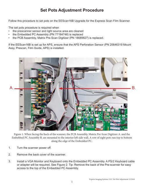
Figure 1. When facing the back of the scanner, the PCB Assembly, Matrix Pre-Scan Digitizer A. and the<br />
Embebbed PC Assembly B. are mounted to the interior left side wall. A row of eight pots run top to bottom<br />
along the edge of the Embedded PC.<br />
1. Turn the scanner power off.<br />
2. Remove the back cover of the scanner.<br />
3. Install a VGA Monitor and Keyboard onto the Embedded PC Assembly. A PS/2 Keyboard cable<br />
or adapter will be required. See Figure 2. Tip: Remove the back of the Pre-scanner for easy<br />
access to the top of the Embedded PC Assembly.<br />
1<br />
<strong>Express</strong> <strong>Imaging</strong> <strong>Systems</strong>, LLC. <strong>Set</strong> <strong>Pots</strong> <strong>Adjustment</strong> 12/2010
C. D.<br />
C. D.<br />
Figure 2. VGA Monitor D. and PS/2 Keyboard C. ports are located at the top of the Embedded PC Assembly.<br />
4. Turn the scanner power on and wait for the PC to boot up. Once the PC has booted, the screen in<br />
Figure 3. will appear.<br />
Figure 3. Boot screen for EEScan16B PC.<br />
5. Press the S key on the keyboard. The <strong>Set</strong> <strong>Pots</strong> screen, Figure 4. will appear.<br />
<strong>Express</strong> <strong>Imaging</strong> <strong>Systems</strong>, LLC. <strong>Set</strong> <strong>Pots</strong> <strong>Adjustment</strong> 12/2010<br />
2
Figure 4. The <strong>Set</strong> <strong>Pots</strong> screen.<br />
6. On the monitor, the fi rst column on the left of the screen, R4, reads from the fi rst (topmost) pot on<br />
the PCB Assembly, Matrix Pre-Scan Digitizer. Reading left to right each column corresponds to a<br />
pot, top to bottom.<br />
7. Starting with R4, fi nd the reading for Blue. Adjust the pot to bring the highest setting in the column<br />
to read 63200. Turn the pot clockwise to lower the reading, counter-clockwise to raise it. Do this<br />
for all the pots, except R15 and R16.<br />
Note: If the scanner is set up for APS and the APS Perforation Sensor is installed, then adjust<br />
R15 and R16 to 2500. If the scanner is not set up for APS, then adjust R15 and R16 as<br />
low as they will go.<br />
8. Press the Esc key on the keyboard to stop the <strong>Express</strong> Scan program.<br />
9. Turn the scanner power off.<br />
10. Disconnect the Monitor and Keyboard from the Embedded PC.<br />
11. Replace the back cover of the scanner.<br />
12. Turn the scanner power on. This will reboot the Embedded PC. The scanner is now ready for<br />
normal operation.<br />
3<br />
<strong>Express</strong> <strong>Imaging</strong> <strong>Systems</strong>, LLC. <strong>Set</strong> <strong>Pots</strong> <strong>Adjustment</strong> 12/2010