Couplers - Narda
Couplers - Narda
Couplers - Narda

Create successful ePaper yourself
Turn your PDF publications into a flip-book with our unique Google optimized e-Paper software.
Introduction<br />
<strong>Couplers</strong><br />
Integrated Microwave<br />
Assemblies (IMAs)<br />
Passive<br />
Components<br />
RF Switching<br />
Products<br />
Power Monitors<br />
and Sensors<br />
The ability of a dual directional coupler to provide an<br />
accurate measure of incident or reflected power is<br />
enhanced by the tracking between the incident and<br />
reflected output ports. Therefore, the coupling variation<br />
of frequency sensitivity of the reflected output port<br />
should ideally be identical to that of the incident output<br />
port. RF power applied to the load is reflected to some<br />
degree depending on load characteristics, thereby<br />
resulting in a voltage standing wave ratio (VSWR) which<br />
is reflected back to the main line output port. This<br />
reflected power is coupled out of the reflected output<br />
port at a level 10 dB down from the reflected power<br />
level at the load. Since the tracking of the forward and<br />
reverse ports is held to a total of 0.3 dB, the coupling<br />
variation at the reflected output port closely follows<br />
that of the incident output port.<br />
In addition to exhibiting excellent tracking characteristics,<br />
the dual directional coupler also features as high a<br />
directivity as possible. Directivity can be expressed as<br />
the ratio of power being coupled out of the reflected<br />
port, with the main line output terminated by a precision<br />
termination, to the power being coupled out of<br />
the incident port. If a portion of the incident power is<br />
coupled out of the reflected output port it essentially<br />
adds, randomly, to the reflected power from the load,<br />
thereby introducing an error. Likewise, if a portion of the<br />
reflected power appears at the incident output port, it<br />
adds to the normal incident coupled power. Therefore,<br />
a true measure of incident and reflected power for accurate<br />
determination of reflection coefficient and VSWR<br />
depends on coupler directivity; the higher the directivity,<br />
the more accurate the measurement. As previously<br />
mentioned, the reflectometer coupler exhibits a directivity<br />
of 45 dB minimum at L-band.<br />
The single-ended coupler is a single air-line directional<br />
coupler for use in measuring transmission gain or loss<br />
characteristics in a swept measurement setup with the<br />
reflectometer coupler, or for use in RF power measurement<br />
setups. Besides exhibiting similar high directivity<br />
to the reflectometer coupler, in each of the five bands,<br />
the coupled output port (10 dB) of this device also provides<br />
tracking (0.3 dB) with respect to the incident port<br />
of the reflectometer set. As a result, simultaneous measurement<br />
of reflection coefficient and transmission gain<br />
or loss characteristics is possible in a single swept measurement<br />
system.<br />
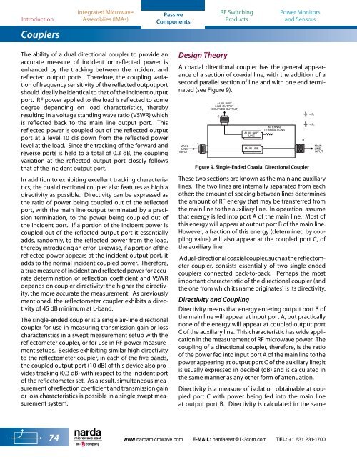
Design Theory<br />
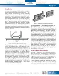
A coaxial directional coupler has the general appearance<br />
of a section of coaxial line, with the addition of a<br />
second parallel section of line and with one end terminated<br />
(see Figure 9).<br />
MAIN<br />
LINE<br />
INPUT<br />
A<br />
AUXILIARY<br />
LINE OUTPUT<br />
(COUPLED OUTPUT)<br />
C<br />
AUXILIARY<br />
LINE<br />
MAIN LINE<br />
INTERNAL<br />
TERMINATIONS<br />
Figure 9. Single-Ended Coaxial Directional Coupler<br />
A<br />
C = P 1<br />
B<br />
C = P 2<br />
MAIN<br />
LINE<br />
INPUT<br />
These two sections are known as the main and auxiliary<br />
lines. The two lines are internally separated from each<br />
other; the amount of spacing between lines determines<br />
the amount of RF energy that may be transferred from<br />
the main line to the auxiliary line. In operation, assume<br />
that energy is fed into port A of the main line. Most of<br />
this energy will appear at output port B of the main line.<br />
However, a fraction of this energy (determined by coupling<br />
value) will also appear at the coupled port C, of<br />
the auxiliary line.<br />
A dual-directional coaxial coupler, such as the reflectometer<br />
coupler, consists essentially of two single-ended<br />
couplers connected back-to-back. Perhaps the most<br />
important characteristic of the directional coupler (and<br />
the one from which its name originates) is its directivity.<br />
Directivity and Coupling<br />
Directivity means that energy entering output port B of<br />
the main line will appear at input port A, but practically<br />
none of the energy will appear at coupled output port<br />
C of the auxiliary line. This characteristic has wide application<br />
in the measurement of RF microwave power. The<br />
coupling of a directional coupler, therefore, is the ratio<br />
of the power fed into input port A of the main line to the<br />
power appearing at output port C of the auxiliary line; it<br />
is usually expressed in decibel (dB) and is calculated in<br />
the same manner as any other form of attenuation.<br />
Directivity is a measure of isolation obtainable at coupled<br />
port C with power being fed into the main line<br />
at output port B. Directivity is calculated in the same<br />
B<br />
74<br />
microwave-east<br />
an<br />
company<br />
www.nardamicrowave.com E-MAIL: nardaeast@L-3com.com TEL: +1 631 231-1700