Narda Announces Expanded Waveguide Product Line
Narda Announces Expanded Waveguide Product Line
Narda Announces Expanded Waveguide Product Line
- No tags were found...

Create successful ePaper yourself
Turn your PDF publications into a flip-book with our unique Google optimized e-Paper software.
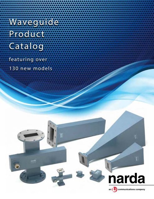
<strong>Waveguide</strong><strong>Product</strong>Catalogfeaturing over130 new models
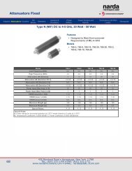
Adapters (2.92 mm, SMA, N)Introducing <strong>Narda</strong> Microwave’s expanded waveguide product line...<strong>Waveguide</strong> to Coaxial (SMA and 2.92mm) AdaptersFrequency Model <strong>Waveguide</strong> Flange Flange VSWR Power Power Max. Weight Max. Weight(GHz) Size Type Equivalent To (Max.) (CW) Watts (Peak) kW (lbs.) (kg)1.70 - 2.60 4617A WR430 CPRF UG-1711/U 1.25 50 3 1.30 0.592.60 - 3.95 4618 WR284 Cover UG-584/U 1.25 50 3 0.90 0.413.30 - 4.90 4619 WR229 CPRF UG-1727/U 1.25 50 3 0.35 0.163.95 - 5.85 4620 WR187 Cover UG-407/U 1.25 50 3 0.45 0.204.90 - 7.05 4621 WR159 CPRF UG-1731/U 1.25 50 3 0.30 0.145.85 - 8.20 4622 WR137 CPRF UG-1733/U 1.25 50 3 0.25 0.117.05 -10.0 4623 WR112 Cover UG-138/U 1.25 50 3 0.17 0.087.00 - 11.0 4624 WR102 Cover MIL-F-3922/70-014 1.25 50 3 0.15 0.078.20 - 12.4 4625 WR90 Cover UG-135/U 1.25 50 3 0.12 0.0510.0 - 15.0 4626 WR75 Cover MIL-F-3922/70-017 1.25 50 3 0.10 0.0512.4 - 18.0 4627 WR62 Cover UG-1665/U 1.25 50 3 0.08 0.0415.0 - 22.0 4628 WR51 Cover MIL-F-3922/70-023 1.25 50 3 0.05 0.0218.0 - 26.5 4629* WR42 Cover UG-597/U 1.25 50 3 0.04 0.0222.0 - 33.0 4630* WR34 Cover UG-1530/U 1.25 10 3 0.03 0.0126.5 - 40.0 4631* WR28 Cover UG-599/U 1.25 10 3 0.03 0.01* Note: Connectors are 2.92mm (female)<strong>Waveguide</strong> to Coaxial (Type N) AdaptersFrequency Model <strong>Waveguide</strong> Flange Flange VSWR Power Power Max. Weight Max. Weight(GHz) Size Type Equivalent To (Max.) (CW) Watts (Peak) kW (lbs.) (kg)1.70 - 2.60 617 WR430 CPRF UG-1711/U 1.25 200 3 1.40 0.642.60 - 3.95 618 WR284 Cover UG-584/U 1.25 200 3 0.80 0.363.30 - 4.90 619 WR229 CPRF UG-1727/U 1.25 200 3 0.45 0.203.95 - 5.85 620 WR187 Cover UG-407/U 1.25 200 3 0.38 0.174.90 - 7.05 621 WR159 CPRF UG-1731/U 1.25 200 3 0.30 0.145.85 - 8.20 622 WR137 CPRF UG-1733/U 1.25 200 3 0.25 0.117.05 - 10.0 623 WR112 Cover UG-138/U 1.25 200 3 0.21 0.107.00 - 11.0 624 WR102 Cover MIL-F-3922/70-014 1.25 200 3 0.16 0.078.20 - 12.4 625 WR90 Cover UG-135/U 1.25 150 2 0.15 0.0710.0 - 15.0 626 WR75 Cover MIL-F-3922/70-017 1.25 150 2 0.13 0.0612.4 - 18.0 627 WR62 Cover UG-1665/U 1.25 150 2 0.12 0.05<strong>Waveguide</strong> to Coaxial (SMA and 2.92mm) Adapters - End LaunchFrequency Model <strong>Waveguide</strong> Flange Flange VSWR Power Power Max. Weight Max. Weight(GHz) Size Type Equivalent To (Max.) (CW) Watts (Peak) kW (lbs.) (kg)2.60 - 3.95 4618E WR284 Cover UG-584/U 1.25 100 3 1.00 0.453.30 - 4.90 4619E WR229 CPRF UG-1727/U 1.25 100 3 0.42 0.193.95 - 5.85 4620E WR187 Cover UG-407/U 1.25 100 3 0.53 0.244.90 - 7.05 4621E WR159 CPRF UG-1731/U 1.25 100 3 0.40 0.185.85 - 8.20 4622E WR137 CPRF UG-1733/U 1.25 100 3 0.35 0.167.05 - 10.0 4623E WR112 Cover UG-138/U 1.25 100 3 0.24 0.117.00 - 11.0 4624E WR102 Cover MIL-F-3922/70-014 1.25 100 3 0.21 0.108.20 - 12.4 4625E WR90 Cover UG-135/U 1.25 100 3 0.17 0.0810.0 - 15.0 4626E WR75 Cover MIL-F-3922/70-017 1.25 100 3 0.12 0.0512.4 - 18.0 4627E WR62 Cover UG-1665/U 1.25 100 3 0.10 0.0515.0 - 22.0 4628E WR51 Cover MIL-F-3922/70-023 1.25 100 3 0.07 0.0318.0 - 26.5 4629E* WR42 Cover UG-597/U 1.25 50 3 0.06 0.0322.0 - 33.0 4630E* WR34 Cover UG-1530/U 1.25 10 1 0.04 0.0226.5 - 40.0 4631E* WR28 Cover UG-599/U 1.25 10 1 0.04 0.02* Note: Connectors are 2.92mm (female)<strong>Waveguide</strong> to Coaxial (Type N) Adapters - End LaunchFrequency Model <strong>Waveguide</strong> Flange Flange VSWR Power Power Max. Weight Max. Weight(GHz) Size Type Equivalent To (Max.) (CW) Watts (Peak) kW (lbs.) (kg)1.70 - 2.60 617E WR430 CPRF UG-1711/U 1.25 1000 20 1.70 0.772.60 - 3.95 618E WR284 Cover UG-584/U 1.25 1000 20 1.15 0.523.30 - 4.90 619E WR229 CPRF UG-1727/U 1.25 1000 20 0.51 0.233.95 - 5.85 620E WR187 Cover UG-407/U 1.25 1000 20 0.53 0.244.90 - 7.05 621E WR159 CPRF UG-1731/U 1.25 1000 15 0.42 0.195.85 - 8.20 622E WR137 CPRF UG-1733/U 1.25 750 14 0.35 0.167.05 - 10.0 623E WR112 Cover UG-138/U 1.25 500 11 0.25 0.117.00 - 11.0 624E WR102 Cover MIL-F-3922/70-014 1.25 500 11 0.23 0.108.20 - 12.4 625E WR90 Cover UG-135/U 1.25 450 11 0.22 0.1010.0 - 15.0 626E WR75 Cover MIL-F-3922/70-017 1.25 500 10 0.20 0.0912.4 - 18.0 627E WR62 Cover UG-1665/U 1.25 500 8 0.17 0.08Standard waveguide flange dimensions and mounting hole orientations are available on the website and in the catalog. Specifications subject to change without notice.
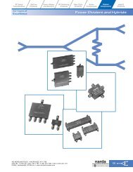
AACBCBModel Dimensions (Inches) ConnectorA B C Type4617A 1.53 4.00 2.34 SMA-F4618 1.13 2.95 1.90 SMA-F4619 1.01 2.28 1.44 SMA-F4620 0.88 2.60 1.96 SMA-F4621 0.84 1.83 1.21 SMA-F4622 0.75 1.70 1.23 SMA-F4623 0.80 1.14 0.67 SMA-F4624 0.77 1.50 1.12 SMA-F4625 0.75 1.00 0.63 SMA-F4626 0.74 1.00 0.63 SMA-F4627 0.73 1.00 0.65 SMA-F4628 0.73 1.00 0.65 SMA-F4629 0.65 1.00 0.75 2.92mm-F4630 0.66 0.56 0.36 2.92mm-F4631 0.60 0.95 0.76 2.92mm-F<strong>Waveguide</strong>-to-Coax Adapter, 2.92 & SMAModel Dimensions (Inches) ConnectorA B C Type617 1.89 4.00 2.30 N-Female618 1.49 2.50 1.51 N-Female619 1.37 2.25 1.35 N-Female620 1.24 2.60 1.90 N-Female621 1.20 2.33 1.70 N-Female622 1.11 2.00 1.47 N-Female623 1.15 1.14 0.68 N-Female624 1.18 1.64 1.14 N-Female625 1.10 1.00 0.63 N-Female626 1.09 1.00 0.63 N-Female627 1.08 1.00 0.65 N-Female<strong>Waveguide</strong>-to-Coax Adapter, Type N2.92mm, SMA orType N Connector,(Type N-Female Shown)BMAX.AModel Dimensions (Inches) ConnectorA B Type4618E 2.75 3.13 SMA-F4619E 2.25 2.63 SMA-F4620E 2.07 2.45 SMA-F4621E 2.00 2.38 SMA-F4622E 1.83 2.21 SMA-F4623E 1.56 1.94 SMA-F4624E 1.50 1.88 SMA-F4625E 1.46 1.84 SMA-F4626E 1.38 1.75 SMA-F4627E 1.25 1.63 SMA-F4628E 1.09 1.47 SMA-F4629E 0.88 1.25 2.92mm-F4630E 0.88 1.25 2.92mm-F4631E 0.86 1.23 2.92mm-F<strong>Waveguide</strong>-to-Coax Adapter, End Launch, SMA & 2.92 mmModel Dimensions (Inches) ConnectorA B Type617E 4.00 4.74 N-Female618E 2.75 3.49 N-Female619E 2.25 2.99 N-Female620E 2.07 2.81 N-Female621E 2.00 2.77 N-Female622E 1.83 2.60 N-Female623E 1.56 2.30 N-Female624E 1.50 2.24 N-Female625E 1.46 2.20 N-Female626E 1.38 2.11 N-Female627E 1.25 1.99 N-Female<strong>Waveguide</strong>-to-Coax Adapter, End Launch, Type NStandard waveguide flange dimensions and mounting hole orientations are available on the website and in the catalog. Specifications subject to change without notice.
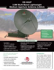
HornsBAStandard Models (Standard Gain)CFreq. (GHz) New <strong>Waveguide</strong> Flange Flange Gain VSWR Max. Weight Max. Weight Dimension A Dimension B Dimension CModel No. Size Type Equivalent (dB) (lbs.) (kg) (inches) (inches) (inches)1.70 - 2.60 651-10 WR430 CPRF UG-1711/U 10 1.25 2.30 1.04 8.00 4.00 10.502.60 - 3.95 652-10 WR284 Cover UG-584/U 10 1.25 1.00 0.45 4.33 3.46 7.50652-15 15 1.18 2.80 1.27 7.96 5.83 15.343.30 - 4.90 653-10 WR229 CPRF UG-1727/U 10 1.25 0.75 0.34 3.62 2.36 6.45653-15 15 1.18 2.80 1.27 6.00 4.41 10.403.95 - 5.85 654-10 WR187 Cover UG-407/U 10 1.25 0.45 0.20 2.89 2.12 5.50654-15 15 1.18 1.00 0.45 4.88 3.57 9.40654-20 20 1.15 2.50 1.13 8.92 6.53 14.934.90 - 7.05 655-10 WR159 CPRF UG-1731/U 10 1.25 1.20 0.54 2.68 1.58 4.28655-15 15 1.18 1.50 0.68 4.33 3.15 8.00655-20 20 1.15 2.40 1.09 9.80 7.64 11.735.85 - 8.20 656-10 WR137 Cover UG-441/U 10 1.25 0.25 0.11 2.02 1.48 3.15656-15 15 1.18 0.45 0.20 3.42 2.50 6.51656-20 20 1.15 1.50 0.68 6.26 4.57 12.197.05 - 10.0 657-10 WR112 Cover UG-138/U 10 1.25 0.15 0.07 1.63 1.18 2.55657-15 15 1.18 0.35 0.16 2.93 2.15 6.65657-20 20 1.15 0.75 0.34 4.97 3.64 10.787.00 - 11.0 658-10 WR102 Cover MIL-F-3922/70-014 10 1.25 0.14 0.06 1.58 1.14 3.00658-15 15 1.18 0.28 0.13 3.04 2.23 6.00658-20 20 1.15 0.70 0.32 5.57 3.94 11.138.20 - 12.4 659-10 WR90 Cover UG-135/U 10 1.25 0.18 0.08 1.58 1.15 2.01659-15 15 1.18 0.25 0.11 2.66 1.95 5.46659-20 20 1.15 0.75 0.34 4.87 3.62 10.0610.0 - 15.0 660-10 WR75 Cover MIL-F-3922/70-017 10 1.25 0.10 0.05 1.26 0.92 1.94660-15 15 1.18 0.19 0.09 2.25 1.33 4.69660-20 20 1.15 0.60 0.27 3.88 2.98 8.0012.4 - 18.0 661-10 WR62 Cover UG-1665/U 10 1.25 0.15 0.07 1.00 0.68 1.00661-15 15 1.18 0.25 0.11 1.69 1.30 2.46661-20 20 1.15 0.50 0.23 2.88 2.11 5.7515.0 - 22.0 662-10 WR51 Cover MIL-F-3922/70-024 10 1.25 0.06 0.03 0.77 0.56 1.43662-15 15 1.18 0.12 0.05 1.36 1.00 2.84662-20 20 1.15 0.35 0.16 2.51 1.93 4.8818.0 - 26.5 663-10 WR42 Cover UG-597/U 10 1.25 0.02 0.01 0.60 0.44 1.25663-15 15 1.18 0.04 0.02 1.14 0.85 2.37663-20 20 1.15 0.13 0.06 2.13 1.56 4.0022.0 - 33.0 664-10 WR34 Cover UG-1530/U 10 1.25 0.02 0.01 0.53 0.39 1.13664-15 15 1.18 0.03 0.01 0.95 0.70 2.12664-20 20 1.15 0.07 0.13 1.76 1.29 3.5626.5 - 40.0 665-10 WR28 Cover UG-599/U 10 1.25 0.01 0.01 0.42 0.32 1.00665-15 15 1.18 0.02 0.01 0.76 0.55 1.87665-20 20 1.15 0.04 0.02 1.38 1.01 3.12BAStandard Models (Wideband)Freq. (GHz) New Input WG Size or Flange Input Cover Flange Gain (dB) Dimension A Dimension B Dimension C Dimension DModel No. Coax Conn. Type Type Equivalent Low to High FQ (inches) (inches) (inches) (inches)Horns Only7.50 - 18.0 667 WRD750 Square Cover n/a 20.5-24 7 5 12.13 -18.0 - 40.0 668 WRD180 Square Cover n/a 14-19 1.47 1.05 2.47 -Horns with Adapter7.50 - 18.0 667A N-Female n/a n/a 20.5-24 7 5 12.13 13.5518.0 - 40.0 668A 2.92mm-F n/a n/a 14-19 1.47 1.05 2.47 3.23CDStandard waveguide flange dimensions and mounting hole orientations are available on the website and in the catalog. Specifications subject to change without notice.
TerminationsCABRectangular W/G Termination, Low PowerFrequency New <strong>Waveguide</strong> Flange Flange VSWR Average Peak Dimension A Dimension B Dimension C(GHz) Model No. Size Type Equivalent (max.) Power (W) Power (kW) (inches) (inches) (inches)1.70 - 2.60 305L WR430 CPRF UG-1711/U 1.04 15.00 15.0 11.00 4.46 2.312.60 - 3.95 306L WR284 Cover UG-584/U 1.04 10.00 10.0 10.80 3.00 1.503.30 - 4.90 307L WR229 CPRF UG-1727/U 1.04 10.00 10.0 7.50 2.42 1.273.95 - 5.85 308L WR187 Cover UG-407/U 1.04 8.00 8.0 6.30 2.00 1.004.90 - 7.05 309L WR159 CPRF UG-1731/U 1.04 7.00 7.0 6.00 1.72 0.925.85 - 8.20 310L WR137 Cover UG-1733/U 1.04 6.00 6.0 5.50 1.50 0.757.05 - 10.0 311L WR112 Cover UG-138/U 1.04 4.00 4.0 5.00 1.25 0.637.00 - 11.0 312L WR102 Cover MIL-F-3922/70-014 1.04 3.00 3.0 4.00 1.12 0.618.20 - 12.4 313L WR90 Cover UG-135/U 1.04 4.00 7.0 4.00 1.00 0.5010.0 - 15.0 314L WR75 Cover MIL-F-3922/70-017 1.04 2.00 2.0 4.00 0.85 0.4812.4 - 18.0 315L WR62 Cover UG-1665/U 1.04 1.50 1.5 4.00 0.70 0.3915.0 - 22.0 316L WR51 Cover MIL-F-3922/70-024 1.04 1.00 1.0 4.00 0.59 0.3418.0 - 26.5 317L WR42 Cover UG-597/U 1.04 0.50 0.5 2.50 0.50 0.2522.0 - 33.0 318L WR34 Cover UG-1530/U 1.04 0.50 0.5 2.50 0.42 0.2526.5 - 40.0 319L WR28 Cover UG-599/U 1.04 0.50 0.5 2.00 0.36 0.22Rectangular W/G Termination, Medium PowerFrequency New <strong>Waveguide</strong> Flange Flange VSWR Average Peak Dimension A Dimension B Dimension C(GHz) Model No. Size Type Equivalent (max.) Power (W) Power (kW) (inches) (inches) (inches)2.60 - 3.95 306M WR284 Cover UG-584/U 1.15 1200 800 11.00 3.00 1.503.30 - 4.90 307M WR229 CPRF UG-1727/U 1.15 1000 800 9.75 2.42 1.273.95 - 5.85 308M WR187 Cover UG-407/U 1.15 750 750 8.38 2.00 1.004.90 - 7.05 309M WR159 CPRF UG-1731/U 1.15 625 625 8.00 1.72 0.925.85 - 8.20 310M WR137 Cover UG-441/U 1.15 500 400 8.00 1.50 0.757.05 - 10.0 311M WR112 Cover UG-138/U 1.15 425 400 7.00 1.25 0.637.00 - 11.0 312M WR102 Cover MIL-F-3922/70-014 1.15 325 300 6.50 1.12 0.618.20 - 12.4 313M WR90 Cover UG-135/U 1.15 225 225 5.50 1.00 0.5010.0 - 15.0 314M WR75 Cover MIL-F-3922/70-017 1.15 200 200 4.50 0.85 0.4812.4 - 18.0 315M WR62 Cover UG-1665/U 1.15 100 200 3.25 0.70 0.3915.0 - 22.0 316M WR51 Cover MIL-F-3922/70-024 1.15 100 120 3.25 0.59 0.3418.0 - 26.5 317M WR42 Cover UG-597/U 1.15 100 120 3.50 0.50 0.2522.0 - 33.0 318M WR34 Cover UG-1530/U 1.15 75 80 3.25 0.42 0.2526.5 - 40.0 319M WR28 Cover UG-599/U 1.15 75 50 4.00 0.36 0.22Standard waveguide flange dimensions and mounting hole orientations are available on the website and in the catalog. Specifications subject to change without notice.
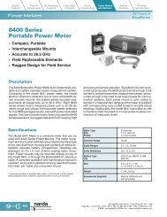
Crossguide Directional CouplersCBSMA (F)Conn.ADCrossguide Directional Couplers, SMA ConnectorsFreq. (GHz) Model <strong>Waveguide</strong> Flange Flange Coupling Max. Deviation Frequency Directivity VSWR VSWR Dim. A Dim. B Dim. C Dim. DNumber Size Type Equivalent (dB) from Nominal Sensitivity (dB min.) Primary Secondary (inches) (inches) (inches) (inches)(dB) (dB max.) (max.) (max.)7.05 - 10.0 4857 WR112 Cover UG-138/U 30 +/-0.5 +/-1.00 20 1.05 1.25 4.20 2.10 3.00 1.508.20 - 12.4 4858 WR90 Cover UG-135/U 30 +/-0.5 +/-1.00 20 1.05 1.25 4.00 2.00 2.75 1.3810.0 - 15.0 4859 WR75 Cover MIL-F-3922/70-017 30 +/-0.5 +/-1.00 20 1.05 1.25 3.75 1.87 2.50 1.2518.0 - 26.5 4862 WR42 Cover UG-597/U 30 +/-0.5 +/-1.00 20 1.05 1.25 2.20 1.10 1.50 0.7526.5 - 40.0 4864* WR28 Cover UG-599/U 30 +/-0.5 +/-1.00 20 1.05 1.25 2.00 1.00 2.50 1.25* Note: Connectors are 2.92mm (female)CBType NConn.ADCrossguide Directional Couplers, Type N ConnectorsFreq. (GHz) Model <strong>Waveguide</strong> Flange Flange Coupling Max. Deviation Frequency Directivity VSWR VSWR Dim. A Dim. B Dim. C Dim. DNumber Size Type Equivalent (dB) from Nominal Sensitivity (dB min.) Primary Secondary (inches) (inches) (inches) (inches)(dB) (dB max.) (max.) (max.)2.60 - 3.95 852 WR284 Cover UG-584/U 30 +/-0.5 +/-1.00 20 1.05 1.25 7.50 3.75 5.00 2.505.85 - 8.20 856 WR137 Cover UG-441/U 30 +/-0.5 +/-1.00 20 1.05 1.25 6.00 3.00 4.00 2.007.05 - 10.0 857 WR112 Cover UG-138/U 30 +/-0.5 +/-1.00 20 1.05 1.25 4.20 2.10 3.00 1.5010.0 - 15.0 859 WR75 Cover MIL-F-3922/70-017 30 +/-0.5 +/-1.00 20 1.05 1.25 3.75 1.87 2.50 1.25Standard waveguide flange dimensions and mounting hole orientations are available on the website and in the catalog. Specifications subject to change without notice.435 Moreland Road, Hauppauge, NY 11788 • Tel : 631.231.1700 • Fax: 631.231.1711 • e -mai l : nardaeast@L-3com.comwww.nardamicrowave.comWGCAT 2/13