pre planning submission op05 derryduff ... - Organic Power
pre planning submission op05 derryduff ... - Organic Power
pre planning submission op05 derryduff ... - Organic Power

You also want an ePaper? Increase the reach of your titles
YUMPU automatically turns print PDFs into web optimized ePapers that Google loves.
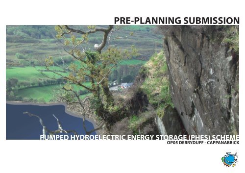
PRE-PLANNING SUBMISSION<br />
PUMPED HYDROELECTRIC ENERGY STORAGE (PHES) SCHEME<br />
OP05 DERRYDUFF - CAPPANABRICK
PRE PLANNING SUBMISSION<br />
OP05 DERRYDUFF - CAPPANABRICK<br />
Contents:<br />
Scoping Document .........................................................................................................5<br />
Project Description....................................................................................................... 11<br />
Site Plan and Photomontages ................................................................................. 17<br />
3
OP05<br />
DERRYDUFF - CAPPANABRICK<br />
SCOPING REPORT<br />
5
Scoping Report for an Environmental Impact Assessment for a Proposed 45MW electric nominally rated Pumped<br />
Hydroelectric Energy Storage (PHES) Scheme, at Derryduff-Cappanabrick, Coomhola, Bantry, Co. Cork.<br />
This scoping report has been written in accordance with the Guidance on EIA Scoping from the European<br />
Commission, June 2001, which states:<br />
A scoping report should identify the content and extent of the information to be provided by the developer<br />
to the competent authority. In particular, scoping reports and opinions will always identify the types of<br />
environmental impacts to be investigated and reported in the environmental information.<br />
Specifically the scoping report should cover:<br />
1. Types of alternative which ought to be considered<br />
2. Baseline studies which are required to characterise the existing environment<br />
3. Any special requirements for baseline studies<br />
regarding their geographical extent or timing e.g. because of seasonal changes in fauna and flora<br />
4. Level of detail of investigations required<br />
5. Methods to be used to <strong>pre</strong>dict the magnitude of environmental effects<br />
6. Criteria against which the significance of effects should be evaluated<br />
7. Types of mitigations to be considered<br />
8. Any further consultations to be carried out during the environmental studies<br />
9. Structure, content and length of environmental information EIS<br />
10. Membership and management of the EIA team<br />
11. Work plan and resourcing for the environmental studies<br />
In summary there are three key questions to be answered:<br />
• What effects could this project have on the environment?<br />
• Which of these effects are likely to be significant and therefore need particular attention in the environmental studies?<br />
• Which alternatives and mitigating measures ought to be considered in developing the proposals for the project?<br />
EIS Scoping<br />
1. Types of alternative which ought to be considered<br />
The project will be assessed for alternative technology, alternative locations, alternative turbine insertion layouts,<br />
alternative grid access options, and alternative input energy sourcing options, in the context of the constraints of<br />
the existing environment and regulatory framework at national and local levels.<br />
2. Baseline studies which are required to characterise the existing environment.<br />
Studies will be carried out to examine the impacts in the various categories listed in Schedule 2 of S.I. No. 93 of 1999.<br />
These impacts are:<br />
1. Landscape and visual impact<br />
2. Noise<br />
3. Other impacts on human beings<br />
4. Hydrology<br />
5. Air and climate<br />
6. Cultural heritage<br />
7. Ecology<br />
8. Land use<br />
9. Soils and geology<br />
10. Material assets<br />
11. Electro-magnetic effects<br />
12. Interaction of the foregoing<br />
3 Any special requirements for baseline studies regarding their geographical extent or timing<br />
3.1 Ecology<br />
Studies to assess the existing environment in the context of species <strong>pre</strong>sent will involve correct timing in respect to<br />
seasonal behaviour, and will be timed accordingly.<br />
The studies will involve the following:<br />
1. Record species of conservation concern<br />
2. Record breeding birds<br />
3. Record breeding mammals<br />
4. Assess potential impacts on aquatic species and habitat<br />
4 Level of detail of investigations required<br />
4.1 Ecology<br />
Studies should examine the flora and fauna of the proposed site location, and refer to the <strong>pre</strong>sence or absence<br />
of the below species on or near the site.<br />
Species of Conservation Concern:<br />
• Salmon<br />
• Freshwater mussel<br />
• Short-eared owl (Annex I on EU Birds Directive)<br />
• Merlin (Annex I on EU Birds Directive)<br />
• Peregrine Falcon (Annex I of EU Birds Directive)<br />
• Otter<br />
The aquatic environment of surface drainage will be assessed to quantify any risk to aquatic fauna, including<br />
freshwater mussels and salmonids, from sedimentation.<br />
4.2 Geology<br />
The geological survey will investigate soil and rock conditions and stability at the proposed development<br />
location and the access road.<br />
4.3 Hydrology<br />
The hydrological investigation will quantify the hydrological implications on wells, water sources, streams and<br />
the Coomhola River that may result from the proposed development, if any.<br />
4.4 Visual Impacts<br />
Visual photomontage will be used to assess the visual impact of the proposal, and Zone of Theoretical<br />
Visibility analysis will be carried out from the proposed development where potential visibility of the proposed<br />
development exists.<br />
4.5 Noise<br />
Noise studies will include sampling of background noise levels and correlation with <strong>pre</strong>dicted noise emissions<br />
from the proposed project as <strong>pre</strong>dicted outside occupied dwelling houses near the proposed development.<br />
5 Methods to be used to <strong>pre</strong>dict the magnitude of environmental effects<br />
Full energy chain analysis (FENCH) of carbon and nitrogen inputs and outputs of the proposal will be carried out.<br />
Zone of theoretical influence (ZTV) and photomontages of buildings in the proposal will address visual impacts.<br />
6 Criteria against which the significance of effects should be evaluated<br />
The relevant criteria as established by the local authority regarding energy development are listed below:<br />
6.1 Overall Strategy Objectives (from CDP 2003, Cork CC) (Quotes in Italics)<br />
5.4.1 The energy industry, and utilities, generally have very specific land use <strong>planning</strong> requirements. In<br />
particular, safeguards need to be put in place to ensure that strategic distribution corridors are not compromised<br />
by inappropriate siting of other developments. The renewable energy sector requires more specific treatment<br />
as it raises a number of <strong>planning</strong> issues, particularly in relation to the deployment of wind energy projects. In all<br />
cases, however, it is necessary to ensure that energy projects do not in themselves constitute negative impacts,<br />
particularly in areas of environmental or landscape sensitivity.<br />
6
5.4.2 The context for including specific renewable energy policies in a county development plan is set by<br />
a range of national and international initiatives and targets. It is a subject which is at the core of the entire<br />
sustainable development idea. The governing national policy in this regard is the National Climate Change<br />
Strategy published in October 2000.<br />
5.4.3 As a <strong>planning</strong> authority, it is important to recognise the range of new and developing technologies that<br />
can contribute to minimising greenhouse gas emissions and to securing a greater proportion of our energy<br />
needs from renewable sources.<br />
6.2 Bantry Local Area Plan objectives (from CDP 2003, Cork CC)<br />
5.5.1 The energy industry, and utilities in particular, have very specific land use <strong>planning</strong> requirements. In<br />
particular, safeguards need to be put in place to ensure that strategic distribution corridors are not compromised<br />
by inappropriate siting of other developments. The renewable energy sector requires more specific treatment<br />
as it raises a number of <strong>planning</strong> issues, particularly in relation to the deployment of wind energy projects. In all<br />
cases however, it is necessary to ensure that energy projects do not in themselves constitute negative impacts,<br />
particularly in areas of environmental or landscape sensitivity.<br />
7.9.12 Values associated with the Ridged, Peaked and forested uplands (Landscape)<br />
(The proposed development is located in this landscape zone)<br />
Within County Cork this landscape is valued for its scenic amenity, particularly its rolling countryside, narrow<br />
shallow lakes and complex topography, its expansive views and scenic routes, including the Cousane Gap. This<br />
landscape is also valued locally as a place to live and for its farmland, much of which is of marginal agricultural<br />
quality and is often used for commercial forestry.<br />
18.1.2 It should be noted that the biological quality of this section of the Coomhola river currently meets the<br />
standards set under the Local Government (Water Pollution) Act 1977 (Water Quality Standards for Phosphorous)<br />
Regulations1998. There is a requirement that this good water quality be maintained.<br />
6.3 Objectives General: Energy, Renewable Energy (from CDP 2003, Cork CC)<br />
INF 4-1 Energy Networks and Infrastructure<br />
(a) It is an objective to recognise the national importance of ensuring security of energy supplies for<br />
servicing a whole range of economic sectors.<br />
(b) It is a general objective, where strategic route corridors have been identified, to support the statutory<br />
providers of national grid infrastructure by safeguarding such strategic corridors from encroachment by<br />
other developments that might compromise the provision of energy networks.<br />
(c) It is an objective generally to protect areas of recognised landscape importance from construction of<br />
large scale visually intrusive energy transmission infrastructure. In such circumstances it is an objective<br />
to seek alternative routing or transmission methods.<br />
INF 4-2 Climate Change<br />
It is an objective to support the National Climate Change Strategy and, in general to facilitate measures which<br />
seek to reduce emissions of greenhouse gases.<br />
INF 4-3 Renewable Energy Production<br />
It is an objective to encourage the production of energy from renewable sources, including, in particular that<br />
from biomass, waste material, solar, wave and wind energy, subject to normal proper <strong>planning</strong> considerations,<br />
including in particular impact on areas of environmental or landscape sensitivity.<br />
ZON 3-19 Utilities and Infrastructures<br />
It is an objective to promote the provision of development to meet the operational requirements of utilities<br />
and infrastructure operators.<br />
7 Types of mitigations to be considered<br />
• Siting and Design alternatives<br />
• Water usage rates<br />
• Routing of infrastructure<br />
• Bank protection<br />
• Habitat creation<br />
8 Consultations to be carried out during the environmental studies<br />
• Coomhola Residents Association<br />
• CCC Roads Department regarding proposed alterations to the Rangaroe-Derryduff road<br />
• Planning Department <strong>pre</strong>-<strong>planning</strong> discussion regarding: Scope of Visual Analysis, Grid Connection, <strong>submission</strong> format.<br />
• CCC Environment section<br />
• South-western fisheries Board regarding the Coomhola River<br />
• NPWS regarding ecology<br />
9 Structure, content and length of the environmental information EIS<br />
9.1 Structure<br />
The Environmental Impact Statement which will be submitted together with the Planning Application for the<br />
Proposed 45MW (electric nominally rated) Pumped Hydroelectric Energy Storage Scheme will be composed of<br />
two documents, both to be <strong>pre</strong>sented in A3 format.<br />
The first document, the main body of the EIS will provide a coherent synthesis of the information gathered<br />
during the baseline studies and design process following the <strong>pre</strong>scribed contents as required under EIS<br />
legislation; Statutory Instrument 349 of 1989: European Communities (Environmental Impact Assessment)<br />
Regulations, 1989.<br />
The second document, the appendices, will contain all the baseline and design studies and report which will<br />
have informed the EIS.<br />
The reason that it is proposed to submit as 2 documents and in A3 format is, firstly, to assist the <strong>planning</strong><br />
authority in referring between the EIS Main Body and the baseline and design reports, and secondly to avoid<br />
folded maps and drawings within the documents.<br />
9.2 Content<br />
9.2.1 The Contents of the EIS as <strong>pre</strong>scribed under EIS legislation, [Statutory Instrument 349 of 1989: European<br />
Communities (Environmental Impact Assessment) Regulations, 1989], will contain the following headings for<br />
baseline conditions and <strong>pre</strong>dicted impacts:<br />
• Human beings<br />
• Flora<br />
• Fauna<br />
• Soil<br />
• Water<br />
• Air<br />
• Landscape<br />
• Material Assets<br />
• Cultural Heritage<br />
Design Inputs required for the evaluation of the likelihood and significance of the above:<br />
1. Existing Topography<br />
2. Existing and proposed site levels<br />
3. Plan and elevation drawings of development<br />
4. Existing flora and fauna<br />
5. Landscape photography and visual impact analysis<br />
6. Ambient noise measurement<br />
7. Hydro-geological survey<br />
8. Archaeological survey.<br />
9. Details of air treatment provisions (noise)<br />
10. Employment requirements<br />
11. Operations schedule, security, and environmental management provisions<br />
12. Post operation management restoration proposal.<br />
7
9.2.2 In addition, the following information will be provided, in the context of the EPA<br />
(1995) Advice Notes on Current Practice in the <strong>pre</strong>paration of Environmental Impact Statements: Water<br />
Management projects for Agriculture, Water impoundment (including for hydroelectric generation),<br />
Canalisation, Flood relief. (Project Type 12).<br />
9.2.3 This document states: These project types can give rise to significant impacts,<br />
which can be direct, such as changes in land use and habitats, or indirect, such as facilitation of new<br />
developments (industry, agriculture, infrastructure) which may in turn impact on the environment.<br />
Project Description<br />
Checklist of items to be described<br />
Construction<br />
• Site evaluation/testing<br />
• Time of year, duration and phasing<br />
• Site <strong>pre</strong>paration works<br />
• Employment<br />
• Accommodation<br />
• Working hours<br />
• Acquisition of lands and management prior to development<br />
• Dredging/excavation and spoil deposition<br />
• Construction techniques<br />
• Water course diversions (temporary)<br />
• Pipe laying<br />
• Materials (including sourcing, transportation and storage<br />
• Extensions of infrastructure (water, power, roads, etc.)<br />
• Access<br />
• Dust, Noise, traffic, vibration<br />
• <strong>Power</strong> line connections<br />
• Pipe laying<br />
• Spoil deposition<br />
• Fencing<br />
Operation (including relevant alternatives)<br />
• Operational range of water levels<br />
• Operational range of flows<br />
• Seasonal/Daily variations of operations<br />
• Monitoring and control procedures<br />
• Maintenance systems<br />
• Principal structures, including impoundment structures, access, pipelines, power lines, diversion<br />
channels, control mechanism, buildings and fences<br />
• Maintenance<br />
Decommissioning (if applicable)<br />
• Safety<br />
• Proposals for alternative usage/demolition following closure<br />
• Reversibility of impacts<br />
Growth<br />
• Opportunities and likelihood of expansion<br />
Associated developments<br />
• Intensification of or new land uses<br />
• Re-housing of displaced residences<br />
• Connections to main transmission network (though this may be the subject of a separate application for permission)<br />
• Water pipes<br />
• Adjustment of affected infrastructure<br />
Environmental Effects<br />
Typical significant impacts likely to affect:<br />
Human beings<br />
• Displacement (major water improvement projects)<br />
• Creation/loss of amenity<br />
• Community severance<br />
• Changes to land use and settlement patterns<br />
Flora<br />
• Alterations to habitats due to flooding/drainage<br />
• Indirect impacts due to altered land use practices.<br />
• Aquatic and terrestrial species should be considered<br />
Fauna<br />
• Displacement due to altered habitat<br />
• Disturbance during construction<br />
• Effects of changes in water quality and flow regime<br />
• Effects due to changes in Flora<br />
Soils (and geology)<br />
• Erosion<br />
• Excavation/deposition of soil<br />
• Loss of/changes to soil<br />
Water<br />
• Changes to the physical, chemical, and biotic characteristics of water bodies<br />
• Effects on flow regime<br />
• Changes to water table<br />
Air<br />
• Dust generation (particularly during construction)<br />
Climate<br />
• Reduction in occurrence of mist and fog due to drainage of wetlands<br />
• Local climatic effects, particularly regarding temperature and evaporation due to creation of a reservoir<br />
The landscape<br />
• Direct effects arising due to spoil deposition, dam construction and machinery <strong>pre</strong>sence during construction<br />
• Indirect impacts occurring due to factors such as power lines, water mains and treatment works and<br />
changes in land use.<br />
Material assets<br />
• Roads<br />
• <strong>Power</strong> supply networks<br />
• Water supply<br />
• Potential uses of water resources<br />
Cultural Heritage<br />
• Flooding of monuments, artefacts and settlements<br />
• Disturbance of items of historical importance such as bridges and weirs<br />
• Significant changes in long established land-use patterns<br />
The interaction of the foregoing<br />
Possible Mitigation Options<br />
• Siting and Design alternatives<br />
• Water usage rates<br />
• Routing of infrastructure<br />
• Bank protection<br />
• Habitat creation<br />
8
9.3 Length<br />
It is anticipated that the Main Body of the EIS will run to approximately 50 pages of A3 text not including<br />
graphics, and that the appendices will run to several hundred A3 pages.<br />
10 Membership and management of the EIA team<br />
Erm21c Ltd Project Management, EIA management, and EIS production<br />
Project Manager: Axel Fabritius<br />
Energy Engineering James J. Nolan, Sean Wyse<br />
Civil Engineering Brian Walsh, Niall Fitzsimons & Co.<br />
Soils and Geology Robert Meehan<br />
Hydrology Robert Meehan<br />
Archaeologist Maurice Hurley<br />
Noise & Vibration Dixon Brosnan<br />
Ecology Dixon Brosnan<br />
11 Work plan and resourcing for the environmental studies<br />
• Baseline studies commenced June 2008<br />
• Project defined June 2008<br />
• Pre-<strong>planning</strong> consultations to be completed 30th September 2008<br />
• EIS to be completed 30th September 2008<br />
• Anticipated Planning Application 1st week October 2008<br />
9
OP05<br />
DERRYDUFF - CAPPANABRICK<br />
PROJECT DESCRIPTION<br />
(Excerpt from Draft EIS)<br />
11
12<br />
2 The Proposed Development (Section 2 of EIS)<br />
2.1 Site Location And Suitability<br />
2.1.1 Site Location<br />
The proposed location of the project is in the townlands of Derryduff and Cappanabrick, Coomhola valley,<br />
Bantry, Co. Cork. Specifically, the proposed development site is part of lands belonging to The Unicorn<br />
Foundation and Patrick Murphy.<br />
2.1.2 Site Selection Suitability Criteria<br />
This site has been selected from 2 alternatives based the proposed development because of the following site criteria:<br />
• Compatible land use zoning<br />
• Adequate Length to Height (L/H) ratio and sufficient vertical head to use for gravity flow (>180m gross head)<br />
• Impervious and structurally sound geological conditions<br />
• Low hydrological impact<br />
• Suitable topography to accommodate PHES with minimal landscape disturbance<br />
• Proximity of 110kV grid access (
2.2.3 Positive Impacts<br />
The following environmental benefits of the area will be positively affected by the development:<br />
• Direct local income from sustainable use of the environment will increase significantly, enhancing the economic<br />
integrity and security of the area, including a minimum 1 high quality sustainable job in monitoring, and indirect job<br />
creation through management. Total permanent job creation will be equivalent of 2 full time jobs.<br />
• The facility will require the construction of access roads, a turbine hall, penstock, upper and lower<br />
reservoirs resulting in significant local economic activity during the construction period.<br />
• The project will yield investment return for local and company investors. The facility will be financed<br />
through a prudent combination of debt and equity.<br />
• Strategic energy infrastructure which will be emissions free and imported fuel independent, consistent<br />
with EU, State, and County policy will be commissioned, enhancing the future energy security of the<br />
community.<br />
• The catchment of the Derryduff stream will be increased by placing catching drains along the edge of<br />
the access road to the upper reservoir. This will enhance the productivity of the watershed to the extent<br />
that micro-hydro scheme proposed on the stream by the Unicorn Foundation becomes more viable. The<br />
available penstock head for this micro-hydro scheme will also be increased as a result of the re-routing of<br />
the stream bed around the lower reservoir. (Note: this stream has no fish life, due to its current ephemeral<br />
nature which is caused by low catchment area)<br />
2.2.4 Negative Impacts<br />
The following environmental benefits of the area may be potentially negatively affected by the development:<br />
• The local visual impact is expected to be minimal. Some visibility of the lower reservoir may be<br />
observable from the vicinity of Lough Atooreen on the mountain road from Dromduff to Maugha road in<br />
Tooreen townland. Otherwise visual impacts will be restricted to the outer bank of the upper reservoir<br />
and the exposed sections of the penstock.<br />
• The current use of the proposed site (approximately 30 acres) for grazing sheep will be lost of the site is developed.<br />
• The existing blanket peat in the areas of the two reservoirs will be removed.<br />
• The water supply to the Derryduff farm community and Unicorn Foundation is sourced on the mountain<br />
from surface runoff. During construction of the upper reservoir and its access road, potential contamination of<br />
this water supply could arise from soil and rock disturbance. This will be mitigated by the installation of a<br />
sand & gravel filtering beds on the water supply, to be installed prior to the commencement of works at<br />
higher elevation than the water supply intake.<br />
As is evident from the above list of impacts arising, the benefits that would be foregone in a do-nothing scenario<br />
are significantly greater than the loss of benefits which would result from the development. An attempt to<br />
quantify the economic costs and benefits on an annual basis is given below.<br />
Annual National Economic Cost-Benefit Proposed PUMPED HYDRO ELECTRIC STORAGE SCHEME.<br />
Item Cost Benefit<br />
National Fuel import costs avoided (60,000 barrels year @€75/barrel, based on gas power) 0<br />
4,500,000<br />
National Carbon Payments avoided €20 x 36,000 tonnes 0 720,000<br />
Lost sheep grazing (1 sheep/2ha, 12.5ha lost, sheep @70) 400<br />
National Economic Totals 400 5,220,000<br />
• The net national economic benefits over 50 years will be in the order of €260,000,000.<br />
• A Do-nothing scenario would result in the avoidance of potential savings on the national obligation to<br />
purchase fuel and carbon emissions rights worth over €0.26 billion, over fifty years.<br />
• The proposed development does not have nor will have any detrimental permanent environmental<br />
impacts on the area or surroundings, if properly designed, and operated.<br />
• There are no environmental benefits from a do-nothing scenario.<br />
• In conclusion, a do-nothing scenario should not apply in this case. This is the century where the whole<br />
world is starting to take corrective action against anthropogenic climate change, and to start developing<br />
towards a sustainable future. In this new world paradigm, the generation of electricity, a commodity that<br />
everybody enjoys and nobody wants to give up, will largely come from low carbon renewable energy.<br />
The proposed project will provide a portion of that future energy requirement.<br />
2.3 Construction<br />
2.3.1 Public Road Access / Coomhola Bridge/ Ford<br />
There are two access alternatives to cross over the Coomhola River from the main Coomhola- Borlin road, which<br />
are currently under evaluation:<br />
• Via Derryduff bridge - widen existing bridge, and widen road to Derryduff farm from bridge<br />
• Improve private existing ford access to Derryduff farm from Rangaroe, upstream (~1km) of bridge<br />
2.3.2 Site Compound, Temporary Site Offices<br />
At the initial stages of construction, the proposed area for the site offices and compound will be stripped of<br />
topsoil and this will be banked around the area. Teram geotextile will be placed on the subsoil to stop the<br />
particles boiling up through the two layers of compacted clause 804. Included in the compound will be parking<br />
for fifteen cars/vans, bunded diesel storage to 110% of the largest tank and a concrete area with gull to a grease<br />
trap and silt trap to catch spills and sediment. A perimeter hoarding 2.4m high, will be constructed and painted<br />
green to match the existing surroundings of trees and green area.<br />
Temporary site structures will consist of ten port-cabins and six small lockable steel shipping containers for small<br />
plant and hand held tool storage, and personel protective equipment (PPE) storage. One of the port-cabins will<br />
be for the subcontractors that are expected during the construction period, and the other will be a larger one for<br />
canteen and meeting room. A toilet unit will also be provided and regularly maintained and content disposed of<br />
by a registered waste management company. The waste management will also provide a number of skips/ large<br />
bins for recyclables and non recyclable materials that will be generated on site and within the compound.<br />
2.3.3 Access Roads<br />
The following sequence of on site road construction will be required<br />
• Improve road from ford to Derryduff forestry road entrance (if using ford for access)<br />
• Improve existing forestry road<br />
• Build new road to access powerhouse/lower lake<br />
• Build new road to reach top lake<br />
• Roads on dam crest<br />
• Ramps onto crest and ramp down to reservoir bed<br />
Access roads into and within the site will range from 4.5m to 6m width and will be laid using 500mm of 50mm<br />
aggregate down. Some sections of this road will be finished with tarmacadam. Stone will be obtained from<br />
quarrying stone during lake excavation, and no imported stone will be required.<br />
2.3.4 Structures.<br />
The proposed project is a large civil engineering project, involving heavy structures to contain the forces of<br />
standing and contained flowing water, in addition to the pump turbine. All structures will be designed by one of<br />
the leading structural engineering practices in the country, Niall Fitzsimons and Company, Consulting Civil and<br />
Structural Engineers. The structures required are described below. Detailed foundation design will be carried out<br />
by, post obtaining <strong>planning</strong> permission.<br />
Peat Storage<br />
Two peat storage structures will be placed on site. The structural integrity of these stockpiles will be provided<br />
by bunding structures and the gravtitational integrity of the peat which will improve with time as the moisture<br />
content reduces. The stockpiles will be sealed by smoothing to allow <strong>pre</strong>cipitation to be shed from their surface.<br />
Gravity Dams For Reservoirs<br />
Dams will be constructed using excavated stone placed on appropriately designed rock benches. As the name<br />
infers, the force of gravity is used to provide structural integrity.<br />
Reservoirs<br />
The reservoirs will be constructed on the existing bedrock, and foundations will be blasted partly into the rock.<br />
A porous drainage layer will lie on top of the bedrock to allow for the cotrol of groundwater seepage. This is<br />
overlaid by an impermeable flexible composite of bituminised concrete and bitumen. The leakage tolerance of<br />
the reservoirs will be 5 l/s each from an economic point of view. Nevertheless, the performance of modern state<br />
of the art sealings are better than 1 l/s.<br />
13
Intake structures<br />
A sluiced water intake/fill structure will be constructed at each reservoirs from re-inforced concrete to allow<br />
water to be drained pumped between reservoirs. The intake structure for the bottom reservoir will be located at<br />
least 15m below the lowest point of the lower reservoir to provide sufficient back <strong>pre</strong>ssure on the pump-turbine<br />
to eliminate cavitation. The intake structure of the upper reservoir will be located at the level of the base of the<br />
upper reservoir. Appropriate sluice controls and trashracks will be included<br />
Penstock<br />
A penstock pipe will transport the water at a rate of 25m 3 /s between reservoirs. This pipe will be situated partly<br />
over-ground and partly underground, making maximum use of the topographical features of the site. The pipe<br />
will be composed of <strong>pre</strong>-manufactured section of 18m long which are bolted together in series of 3 sections.<br />
Each series is linked to the next by a massed concrete foundation haunch. Haunches will be soaced 54m apart.<br />
Turbine<br />
• Pump-turbine (Voith Siemens)<br />
• 1 no.<br />
• Rated output: 45 MW<br />
• Turbine rated net head: 210m<br />
• Required flow rate 25 m³/s<br />
• Max. pump Head: 231m<br />
• The power plant will run fully automatically.<br />
Fig. 2 Pump Turbine Schematic Drawing (Indicative Only)<br />
2.3.8 Construction Traffic<br />
Project generated traffic will include deliveries of plant and machinery and of oversized loads. The oversized<br />
loads will not require public road alterations. The transportation of these loads will require special permit and<br />
the consent of ‘An Garda Siochana’. Once these have been obtained the components will be transported from<br />
Ringaskiddy port to site. There will also be daily commutes of plant operators, office staff, electricians, engineers<br />
and trades people. Assuming 30 no. workers, all travelling in their own vehicles, there will be an increase of 30<br />
vehicles commuting daily.<br />
14<br />
Fig. 1 <strong>Power</strong>house - “White Tank” (Indicative Only)<br />
<strong>Power</strong>house<br />
A pit containing a wet cylindrical well approximately 37.5m deep will house the pumpturbine on the northern<br />
side of the lower reservoir. The building pit will be enclosed by a bored piled curtain wall (~1m thick) forming a a<br />
waterproof “white tank”. This structure will be underground, and covered by a low building (See Fig. 6).<br />
Turbine Hall<br />
The structural skeleton of the building will be erected, roofed, and clad once placing of the turbine plant<br />
elements by gantry crane is complete.<br />
2.3.5 External Service Pipes And Ducts<br />
All telecommunicatons and electrical cables for the proposed development will be buried underground under<br />
the access roads on site with a minimum of 1 meter cover from ground level, labeled with suitable yellow<br />
warning tape at 0.5m from ground surface and 0.8m from ground surface at the top of the surround gravel<br />
to warn off future excavations. Electrical cables will be run to a substation adjacent to the turbine hall. A<br />
110kV underground cable will follow the route of the access road to the public road at the Unicorn foundation<br />
entrance, and then follow under the public road over the Derryduff bridge to Rangaroe, Coomhola, Dromduff<br />
west to Ballylickey Bridge and the connection at the ESB 110kV substation.<br />
2.3.6 Site Works Surfacing<br />
The access roads will be paved with tarmac or finished with crushed stone, and have kerb and gullies to collect<br />
storm water runoff to sedimentation basins.<br />
2.3.7 Plant Operational Technology Installation And Mechanical And Electrical Fit-Out<br />
Design parameters:<br />
• Location to minimize bends in the penstock pipes<br />
• Location of turbine below lake bottom<br />
• Deeper Pool at <strong>Power</strong> House containing outflow/intake structures<br />
2.3.9 Construction Health and Safety<br />
Relevant legislation includes, ‘The Safety, Health and Welfare at Work Act 1993-2003, Irish Construction<br />
regulations 2001, and all of the other up to date Safety, Health and Welfare best practice Guidance Documents.<br />
A number of these relevant documents include PPE, Manual Handling, Working with ladders, working at night,<br />
quarrying and surface mining operations, quarry vehicles, working on in or near excavations, signage, slips<br />
trips and falls at work, working at heights. This is not an exhaustive list however these are all relevant to a large<br />
project such as a PHES development. Hazards identified associated with this project include, oversized loads,<br />
lifting materials, pipe sections and turbine components to heights, working at heights, underground power<br />
lines, electricity at commissioning, excavations, slips, trips and falls, moving vehicles and plant, etc. A 2.4m high<br />
perimeter chain link fence will be carried out around the reservoir perimeters.<br />
2.3.10 Land Use Requirements During Construction Phase<br />
The approximate total land take required for the proposed project is given below. This area re<strong>pre</strong>sents less than<br />
12% of the existing upland site, which is defined as lands within the site boundaries of the property involved in<br />
the project, which are not forested or improved for grazing (116ha).<br />
Item Area [m2]<br />
Access Road to Site 10000<br />
Area of Surfaced Roads 33670.3<br />
Buildings 3840<br />
Upper Reservoir 30072.5<br />
Lower Reservoir 41288.5<br />
Penstock 4629.4<br />
Stillin Basins 2699.4<br />
Peat stock pile 1 8720.8<br />
Peat stock pile 2 2690.9<br />
Total land use requirement 133771.8
2.3.11 Waterworks<br />
Top Reservoir<br />
Design:<br />
• Gravity Rockfill Dam with vertical steel enforced concrete walls on the upstream side – ring structure,<br />
partly concrete gravity dam with buttresses<br />
• Reservoir Bed: asphaltic liner (e.g. top to bottom: with mastic coating, asphalt concrete, bituminized<br />
binder course, asphalt filter, asphalt binder, gravel layer)<br />
• Drainage system to monitor possible seepage and a fibre optic leakage detection system<br />
• Intake structure: side intake structure<br />
• Trashrack<br />
• Freeboard: 0.5 m (based on max. wind speed ever recorded in Ireland [56 m/s] 300m fetch, 15m depth)<br />
• Wave wall 0.5m high on upstream edge of the dam<br />
Penstock<br />
Design:<br />
• 1 pipe running through gorge with as few as possible direction changes. Changes of less than 10° are more<br />
or less negligible in terms of friction, bigger changes will cause increasing friction meaning a loss in efficiency<br />
• Internal Pipe diameter expected at 2.5m (depending on required flow rate (anticipated between 25 m³/s)<br />
• Pipe partly over ground level; could be mounted on Stilts (anchored into the rock); partly bruied in a trench.<br />
• Pipe material: glass-fibre-reinforced, polymer mortar or steel pipes<br />
Fig. 6 Penstock - Steel Pressure Pipe (Indicative Only)<br />
Fig. 3 Top Reservoir - Road on Dam Crest (Indicative Only)<br />
Fig. 4 Top Reservoir - Gravity Rockfil Dam with partly vertical steel<br />
inforced walls (Indicative Only)<br />
Bottom Reservoir<br />
Design:<br />
• Two Gravity Rockfill Dams - one to the south and one small one next to the forestry; upstream face: asphaltic lining<br />
• Reservoir Bed: asphaltic liner (e.g. top to bottom: with mastic coating, asphalt concrete, bituminized<br />
binder course, asphalt filter, asphalt binder, gravel layer) on top of natural bedrock<br />
• Drainage system to monitor possible seepage and a fibre optic leakage detection system<br />
• Outlet structure: draft tubes, draft tube extensions serve as outlet (part of power house structure)<br />
• Trashrack<br />
• Spillway<br />
• Freeboard:<br />
• 0.5 m (based on max. wind speed ever recorded in Ireland [56 m/s] 300m fetch, 15m depth)<br />
• Wave wall 0.5m high on upstream edge of the dam<br />
Stilling Basins (sedimentation ponds):<br />
Design:<br />
• 3 basins in a row at three different height levels (“steps”)<br />
• Position: Below main gravity dam – lower reservoir<br />
Grid Connection (at Ballylickey Bridge 110kVGrid substation)<br />
Via underground (under public road) 7km cable (110kV)<br />
Rerouted Stream<br />
The lower reservoir will be situated on the existing route of the Derryduff stream. Consequently the stream will<br />
have to be re-routed to allow the construction of the lower reservoir. The new route will be west of the lower lake<br />
parallel to its bank and bring the stream via a channel to the middle of the crest of the main dam and connect to<br />
a “mini-penstock” for a Unicorn Micro-hydroelectric Scheme.<br />
2.3.12 Construction Timetable<br />
The following proposed construction schedule is anticipated to start within 12 months of receipt of <strong>planning</strong><br />
and grid permits. Once construction is started, commissioning is projected within 30 months.<br />
Activity<br />
Table 1: Proposed Construction Schedule - Derryduff - Cappanabrick<br />
Duration (Month<br />
1 2 3 4 5 6 7 8 9 10 11 12 13 14 15 16 17 18 19 20 21 22 23 24 25 26 27 28 29 30<br />
Fig. 5 Lower Reservoir - Rockfill Dam with Asphaltic Liner(Indicative Only)<br />
1.) Construct access bridge off main road / ford<br />
2.) Site access Clearance & Site Compound Setup<br />
3.) Construct access road to lower lake<br />
4.) Lower Lake soil/peat excavation<br />
5.) Construct access road to upper lake<br />
6.) Lower Lake rock removal & formation of banking/retaining walls<br />
7.) Construction of Turbine Carvern to lower lake<br />
8.) Upper Lake soil/peat excavation<br />
9.) Upper Lake rock removal & formation of banking /retaining walls<br />
10.) Construction of Upper Lake Inlet Structure<br />
11.) Excavation & foundation works for pipe line path<br />
12.) Laying of High-Pressure Pipeline from upper to lower lake<br />
13.) Apply water tight asphalt lining to upper and lower lakes<br />
14.)Fit-out of Cavern- Pump Turbine, Generator etc<br />
15.) Construction & fit-out of Transformer building<br />
16.) Laying underground/overground high voltage cable from site<br />
to nearest local network<br />
17.) Testing/Commissioning
The filling of the lakes to an operational level will take 15-24 weeks depending on the <strong>pre</strong>cipitation levels.<br />
2.4 Operations<br />
2.4.1 Overview<br />
The proposed Cappanabrick-Derryduff PHES project will be commissioned to supply electric power from a<br />
hydroelectric pump-turbine, to be produced by pumping 280,000 meters cubed water to a gravitational head of<br />
210 meters using 49MW of electric power sourced from the grid during off peak hours of electricity demand, and<br />
drawing down this head while producing 45MW of power from the turbine which power is delivered to the grid<br />
during peak hours. All of the input electric power will be sourced from grid connected wind energy projects.<br />
The process will transform un<strong>pre</strong>dictable and variable windpower to reliable, dispatchable clean energy<br />
delivered to the grid.<br />
Electric Energy<br />
The PHES scheme will deliver power 4 hours per day, corresponding to peak demand from 0600-0800 and 1700-<br />
1900. The scheme will accept energy off peak for from 4 up to 20 hours per day depending on the available<br />
wind energy. Energy is lost in the process through resistance and less than 100% efficiency in the pump and<br />
turbine. These losses are more than compensated both in value and power quality, by the fact that intermittent<br />
and un<strong>pre</strong>dictable power is delivered via PHES as a <strong>pre</strong>dictable quality product in time and volume. The amount<br />
of wind energy capacity that will need to be available to supply the scheme is approximately 30MW installed<br />
capacity of wind turbines, assuming that the wind turbines are on average 35% efficient, and that the PHES<br />
requires a minimum of 196MW hours per day over 20 hours.<br />
2.5 Employment<br />
When operational, the plant will require 1 part time supervisor, and the equivalent of 1.5 full time technical staff<br />
for maintenance and management. The total full time job creation will be 2.<br />
Fig. 6 <strong>Power</strong>house (Indicative Only)<br />
2.6 Decommissioning<br />
It is current practice to re-commission PHES plants once the technical life of its components is over, due to the<br />
increasing penetration of wind power into power grids. For example, many schemes in mainland Europe which<br />
were built in the 1930s are now being re-tooled and upgraded after 70 years of operation (i.e. Waldeck 1 PHES,<br />
Hessen, Germany, owned and operated by EON).<br />
However, in the event that decommissioning is warranted for unforeseen superseding of the technology by<br />
advances elsewhere in power systems, the following will be undertaken as decommissioning:<br />
• All roads and structures will remain in place for future re-use<br />
• The top reservoir be maintained empty<br />
• The bottom reservoir will be maintained full to act as a semi-natural lake, and fish life encouraged<br />
through the introduction of aquatic flora and soil to anchor them.<br />
• Security fence around bottom reservoir will be removed to allow access for recreational purposes.<br />
16
OP05<br />
DERRYDUFF - CAPPANABRICK<br />
SITE PLAN<br />
AND<br />
PHOTOMONTAGES<br />
17
1<br />
2<br />
Legend<br />
1<br />
2<br />
Grid Connection<br />
Existing Public Road<br />
Site Access Road<br />
Photomontage 1 Viewpoint<br />
Photomontage 2 Viewpoint<br />
18
20<br />
PHOTOMONTAGE 1<br />
BEFORE<br />
AFTER
View from accros the valley, top of Knockbreteen<br />
PHOTOMONTAGE 2<br />
21<br />
BEFORE<br />
AFTER