Part 1 - Formula Student
Part 1 - Formula Student
Part 1 - Formula Student

You also want an ePaper? Increase the reach of your titles
YUMPU automatically turns print PDFs into web optimized ePapers that Google loves.
A<br />
TECHNICAL INSPECTOR’S GUIDE<br />
TO THE<br />
2012 FSAE RULES<br />
PART 1<br />
RULES CHANGE SUMMARY<br />
&<br />
ADMINISTRATIVE CHANGES
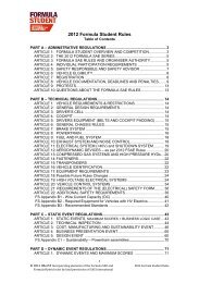
2012 FSAE Rules<br />
• Format<br />
– Index<br />
– Introduction<br />
– <strong>Part</strong> A - Administrative Regulations<br />
– Appendix S - SAE Technical Standards<br />
– <strong>Part</strong> B - Technical Regulations<br />
– Technical Drawings<br />
o Appendix AF - Alternative Frame Rules<br />
o Appendix B-1, Structural Equivalency Form (2 pages)<br />
o Appendix B-2, Impact Attenuator Data Report (3 pages)<br />
– <strong>Part</strong> C - Static Event Regulations<br />
o Appendix C-1 thru’ C-5 Cost Event Appendices<br />
o Appendix C-6 Presentation Judging<br />
o Appendix C-7 Design Judging<br />
– <strong>Part</strong> D - Dynamic Event Regulations
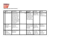
Rules Changes for 2012<br />
For the benefit of the teams, below is a summary of the major rules changes for the 2012<br />
<strong>Formula</strong> SAE competitions. It is not a complete list. If there are any differences between this<br />
summary and the official Rules, the Rules will prevail. Therefore, it is the responsibility of the<br />
competitors to read the Rules thoroughly.<br />
Rule<br />
Number System Change<br />
• Forms Standard forms have been relocated to www.fsaeonline.com<br />
• A.8.5 & A.8.6 Documentation FSAE Michigan & Lincoln-many of documents & submissions<br />
have to be submitted on line.<br />
• A.8.1 Forms A Structural Equivalency Spreadsheet (SES) replaces the<br />
Structural Equivalency Form (SEF)<br />
• B.3.4.5 Tubing Extra bracing required for “bent tubes” in the Primary Structure<br />
• B.3.21.11 Std Attenuator Diagonal or X-brace required with Standard IA.<br />
• B.24.3 Side Impact Str. ALL of top tube must be between 300 & 350 mm above ground.<br />
• B.6.2 Ground Clearance Exact dimension deleted. Must be “sufficient”. (No sliding skirts.)<br />
• B.6.6.2 Jacking Point Must have unobstructed access from rear. (Relaxed aero rules.)
Rules Changes for 2012 (cont’d)<br />
Rule<br />
Number System Change<br />
• B.11.4 Batteries Restrictions & requirements on batteries other than lead-acid.<br />
• B.15 Transponders AMB 260 TraX260 units are now MYLAPS Car/Bike (name change)<br />
• B.17.5 Driver’s Suits Triple layer suits (SFI 3-2A/5 & FIA) now mandatory.<br />
• D.13.1.2 Vehicle Movement Changes to requirements on how a car can be moved in paddock.
Article A - Administrative<br />
• Forms – The standard forms that are required for documentation and<br />
submissions at FSAE competitions have been relocated to<br />
www.fsaeonline.com<br />
• A8.5 Web Based Submission – FSAE Michigan and FSAE Lincoln<br />
Only – Many of the required documents must now be submitted online<br />
through www.fsaeonline.com.<br />
• A8.6 Account Signup for Online Submission – FSAE Michigan<br />
and FSAE Lincoln Only – Teams must comply with certain<br />
requirements when registering at www.fsaeonline.com and submitting<br />
documents online.
Article A8 - Vehicle Documentation, Deadlines &<br />
Penalties<br />
A8.1 Required Documents and Required Forms<br />
• The following documents supporting each vehicle must be submitted by the action<br />
deadlines posted on each competition website or otherwise published by the<br />
organizers.<br />
• B3.8 “Structural Equivalency Spreadsheet (SES)” and Appendix B-1 - Use<br />
required form located at www.fsaeonline.com: or AF2 “Structural Requirements<br />
Certification Form (SRCF)” - Use required form located at www.fsaeonline.com.<br />
• Note – Teams must submit an SES unless using the AF Rules in which case the<br />
SES is superseded by the SRCF. Submit either the SES or the SRCF as required,<br />
but not both.<br />
• B3.21 “Impact Attenuator Data Requirement” - Use required form located at<br />
www.fsaeonline.com.
Article B.3.4 Alternative Tubing and Materials -<br />
General<br />
B.3.4.5<br />
If a bent tube is used anywhere in the primary structure, other than<br />
the front and main roll hoops, an additional tube must be attached<br />
to support it. The attachment point must be the position along the<br />
tube where it deviates farthest from a straight line connecting both<br />
ends. The support tube must have the same diameter and<br />
thickness as the bent tube. The support tube must terminate at a<br />
node of the chassis.
Article B.3.21.11 Standard Attenuator<br />
B.3.21.11 Standard Attenuator<br />
• An officially approved impact attenuator can be found at http://<br />
www.fsaeonline.com/home/page.aspx?pageid=193613e4-<br />
fff1-4ea9-97ec-eb1c07fbe3c0 .<br />
• Teams may choose to use that style of impact attenuator and need not<br />
submit test data with their IAD Report. The other requirements of the<br />
IAD Report must still be submitted including, but not limited to, photos<br />
of the team’s actual attenuator with evidence that it meets the design<br />
criteria given on the website.<br />
However,<br />
The attenuator itself is unchanged from 2011 but requires either the<br />
diagonal or an x-brace in the front bulkhead. Teams can use this<br />
attenuator and test their front bulkhead without the diagonal, but all the<br />
requirements for a student designed attenuator would apply and they<br />
would have to submit the IA data submission like normal.
B.3.21.9<br />
B.3.21 - Impact Attenuator Testing<br />
• During the test, the attenuator must be attached to the anti<br />
intrusion plate using the intended vehicle attachment method.<br />
• The anti-intrusion plate must be spaced at least 50 mm (2<br />
inches) from any rigid surface.<br />
• No part of the anti-intrusion plate may permanently deflect<br />
more than 25.1 mm (1 inch)beyond the position of the antiintrusion<br />
plate before the test.<br />
Note: The 25.4 mm (1 inch) spacing represents the front<br />
bulkhead support and insures that the plate does not intrude<br />
excessively into the cockpit
Article B.3.24 Side Impact Structure for Tube Frame<br />
Cars<br />
B.3.24.3<br />
The locations for the three (3) required tubular members are as follows:<br />
• The upper Side Impact Structural member must connect the Main Hoop and the Front Hoop.<br />
With a 77kg (170 pound) driver seated in the normal driving position all of the member must<br />
be at a height between 300 mm (11.8 inches) and 350 mm (13.8 inches) above the ground.<br />
The upper frame rail may be used as this member if it meets the height, diameter and<br />
thickness requirements.<br />
• The lower Side Impact Structural member must connect the bottom of the Main Hoop and the<br />
bottom of the Front Hoop. The lower frame rail/frame member may be this member if it meets<br />
the diameter and wall thickness requirements.<br />
• The diagonal Side Impact Structural member must connect the upper and lower Side Impact<br />
Structural members forward of the Main Hoop and rearward of the Front Hoop.
Article B.6.2 Ground Clearance<br />
B.6.2 Ground Clearance<br />
Ground clearance must be sufficient to prevent any portion of the car,<br />
other than the tires, from touching the ground during track events.<br />
Intentional or excessive ground contact of any portion of the car other<br />
than the tires will forfeit a run or an entire dynamic event.<br />
Comment: The intention of this rule is that sliding skirts or other devices<br />
that by design, fabrication or as a consequence of moving, contact the<br />
track surface are prohibited and any unintended contact with the ground<br />
which either causes damage, or in the opinion of the ‘dynamic event<br />
organizers’ could result in damage to the track, will result in forfeit of a<br />
run or an entire dynamic event
B.6.6.2 Jacking Point<br />
Article B.6.6.2 Jacking Point<br />
The jacking point is required to be:<br />
• Visible to a person standing 1 meter (3 feet) behind the car.<br />
• Painted orange.<br />
• Oriented horizontally and perpendicular to the centerline of the car<br />
• Made from round, 25 – 29 mm (1 – 1 1/8 inch) O.D. aluminum or steel tube<br />
• A minimum of 300 mm (12 inches) long<br />
• Exposed around the lower 180 degrees (180。) of its circumference over a<br />
minimum length of 280 mm (11 in)<br />
• The height of the tube is required to be such that:<br />
- There is a minimum of 75 mm (3 in) clearance from the bottom of the tube to<br />
the ground measured at tech inspection.<br />
- With the bottom of the tube 200 mm (7.9 in) above ground, the wheels do<br />
not touch the ground when they are in full rebound.<br />
• Access from the rear of the tube must be unobstructed for at least 300mm of<br />
its length
Article B.11.4 Batteries<br />
B.11.4.3 The hot (ungrounded) terminal must be insulated.<br />
B.11.4.5 Battery packs based on Lithium Chemistry other than LiFePo:<br />
a. must be commercially manufactured items<br />
b. must have over voltage, under voltage, short circuit and over<br />
temperature cell protection<br />
B.11.4.6 All batteries using chemistries other than lead acid must be<br />
presented at technical inspection with markings identifying it for<br />
comparison to a datasheet or other documentation proving the pack<br />
and supporting electronics meet all rules requirements
Article B.15 Transponders<br />
B15.1.3<br />
All vehicles must be equipped with at least one MYLAPS Car/<br />
Bike Rechargeable Power Transponder or MYLAPS Car/Bike<br />
Direct Power Transponder.<br />
Note:<br />
Except for their name, AMB TranX260 transponders are<br />
identical to MYLAPS Car/Bike Transponders and fully comply<br />
with this rule. If you own a functional AMB TranX260 it does<br />
not need to be replaced.
Article B.17 Driver’s Equipment<br />
B.17.2 Helmets<br />
A well-fitting, closed face helmet that meets one of the following<br />
certifications and is labeled as such:<br />
- Snell K2000, K2005, K2010, M2000, M2005, M2010, SA2000,<br />
SA2005, SA2010<br />
- SFI 31.2A, SFI 31.1/2005<br />
- FIA 8860-2004<br />
- British Standards Institution BS 6658-85 Type A/FR rating<br />
(Types A and B are not accepted)
Article B.17 Driver’s Equipment<br />
B.17.5 Suit<br />
- SFI 3-2A/5 (or higher)
Article B.17 Driver’s Equipment<br />
B.17.5 Suit<br />
- SFI 3-2A/5 (or higher)<br />
This picture is of the label for a single layer 3-2A/1 suit!
D6.8.3<br />
B.6.8 Skid Pad Scoring<br />
• The following equation is used to determine the scores for the skidpad<br />
event:<br />
SKID PAD SCORE = (47.5 x (Tmax/Tyour) -1) / ((Tmax/Tmin) -1) +<br />
2.5<br />
Where:<br />
Tyour is the average of the left and the right timed laps on your<br />
best run including penalties.<br />
Tmin is the elapsed time of the fastest car<br />
Tmax is 125% of Tmin
D.13.1.2<br />
D.13.1 Vehicle Movement<br />
• Off track vehicles must be pushed at a normal walking pace by<br />
means of a “Push Bar”, (See D13.2) and with a driver in the<br />
cockpit and with another team member walking beside the car.<br />
• The team has the option to move the car either with<br />
(a) all four (4) wheels on the ground or with<br />
(b) the rear wheels supported on dollies, by push bar mounted<br />
wheels, or other means as long as the person in the cockpit has<br />
full control of vehicle movement and can steer and brake<br />
normally. The external wheels supporting the rear of the car must<br />
be non-pivoting so the vehicle travels only where the front wheels<br />
are steered. The driver must always be able to steer and brake<br />
the car normally.
Questions?