data sheet - 3 phase 600 V only - Frontier Power Products
data sheet - 3 phase 600 V only - Frontier Power Products
data sheet - 3 phase 600 V only - Frontier Power Products

You also want an ePaper? Increase the reach of your titles
YUMPU automatically turns print PDFs into web optimized ePapers that Google loves.
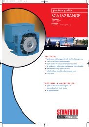
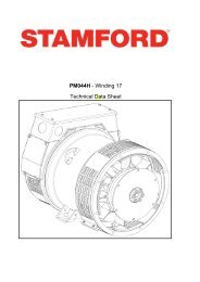
PM144J - Winding 17<br />
Technical Data Sheet<br />
APPROVED DOCUMENT
PM144J<br />
SPECIFICATIONS & OPTIONS<br />
STANDARDS<br />
Marine generators may be certified to Lloyds, DnV, Bureau<br />
Veritas, ABS, Germanischer-Lloyd or RINA.<br />
Other standards and certifications can be considered on<br />
request.<br />
VOLTAGE REGULATOR<br />
AS480 AVR<br />
TERMINALS & TERMINAL BOX<br />
Standard generators are 3-<strong>phase</strong> reconnectable with 12<br />
ends brought out to the terminals, which are mounted at<br />
the non-drive end of the generator. Dedicated single<br />
<strong>phase</strong> generators are also available. A <strong>sheet</strong> steel<br />
terminal box contains provides ample space for the<br />
customers' wiring and gland arrangements. Alternative<br />
terminal boxes are available for customers who want to fit<br />
additional components in the terminal box.<br />
With this self-excited system the main stator provides<br />
power via the AVR to the exciter stator. The high efficiency<br />
semi-conductors of the AVR ensure positive build-up from<br />
initial low levels of residual voltage.<br />
The exciter rotor output is fed to the main rotor through a<br />
three-<strong>phase</strong> full-wave bridge rectifier. The rectifier is<br />
protected by a surge suppressor against surges caused, for<br />
example, by short circuit or out-of-<strong>phase</strong> paralleling. The<br />
AS480 will support limited accessories, RFI suppession<br />
remote voltage trimmer and for the P1 range <strong>only</strong> a 'droop'<br />
Current Transformer (CT) to permit parallel operation with<br />
other ac generators.<br />
The AVR is can be fitted to either side of the generator in its<br />
own housing in the non-drive end bracket.<br />
Excitation Boost System (EBS)<br />
The EBS is a single, self-contained unit, attached to the<br />
non-drive end of the generator.<br />
The EBS unit consists of the Excitation Boost Controller<br />
(EBC) and an Excitation Boost Generator (EBG). Under<br />
fault conditions, or when the generator is subjected to a<br />
large impact load such as a motor starting, the generator<br />
voltage will drop. The EBC senses the drop in voltage and<br />
engages the output power of the EBG. This additional<br />
power feeds the generator’s excitation system, supporting<br />
the load until breaker discrimination can remove the fault or<br />
enable the generator to pick up a motor and drive the<br />
voltage recovery.<br />
WINDINGS & ELECTRICAL PERFORMANCE<br />
All generator stators are wound to 2/3 pitch. This<br />
eliminates triplen (3rd, 9th, 15th …) harmonics on the<br />
voltage waveform and is found to be the optimum design<br />
for trouble-free supply of non-linear loads. The 2/3 pitch<br />
design avoids excessive neutral currents sometimes seen<br />
with higher winding pitches, when in parallel with the mains.<br />
A fully connected damper winding reduces oscillations<br />
during paralleling. This winding, with the 2/3 pitch and<br />
carefully selected pole and tooth designs, ensures very low<br />
waveform distortion.<br />
APPROVED DOCUMENT<br />
SHAFT & KEYS<br />
All generator rotors are dynamically balanced to better<br />
than BS6861:Part 1 Grade 2.5 for minimum vibration in<br />
operation. Two bearing generators are balanced with a<br />
half key.<br />
INSULATION / IMPREGNATION<br />
The insulation system is class 'H'.<br />
All wound components are impregnated with materials and<br />
processes designed specifically to provide the high build<br />
required for static windings and the high mechanical<br />
strength required for rotating components.<br />
QUALITY ASSURANCE<br />
Generators are manufactured using production<br />
procedures having a quality assurance level to BS EN ISO<br />
9001.<br />
The stated voltage regulation may not be maintained in<br />
the presence of certain radio transmitted signals. Any<br />
change in performance will fall within the limits of Criteria<br />
'B' of EN 61000-6-2:2001. At no time will the steady-state<br />
voltage regulation exceed 2%.<br />
DE RATES<br />
All values tabulated on page 6 are subject to the following<br />
reductions<br />
5% when air inlet filters are fitted.<br />
3% for every 500 metres by which the operating altitude<br />
exceeds 1000 metres above mean sea level.<br />
3% for every 5°C by which the operational ambient<br />
temperature exceeds 50°C.<br />
Note: Requirement for operating in an ambient exceeding<br />
60°C must be referred to the factory.<br />
5% For reverse rotation<br />
(Standard rotation CW when viewed from DE)<br />
NB Continuous development of our products entitles us<br />
to change specification details without notice, therefore<br />
they must not be regarded as binding.<br />
Front cover drawing typical of product range.<br />
2
CONTROL SYSTEM<br />
VOLTAGE REGULATION<br />
PM144J<br />
WINDING 17<br />
AS480 AVR WITH EXCITATION BOOST SYSTEM (EBS)<br />
± 1.0 %<br />
SUSTAINED SHORT CIRCUIT REFER TO SHORT CIRCUIT DECREMENT CURVE (page 5)<br />
INSULATION SYSTEM<br />
PROTECTION<br />
RATED POWER FACTOR<br />
STATOR WINDING<br />
WINDING PITCH<br />
WINDING LEADS<br />
STATOR WDG. RESISTANCE<br />
ROTOR WDG. RESISTANCE<br />
EXCITER STATOR RESISTANCE<br />
EXCITER ROTOR RESISTANCE<br />
CLASS H<br />
IP23<br />
0.8<br />
DOUBLE LAYER CONCENTRIC<br />
TWO THIRDS<br />
12<br />
0.229 Ohms PER PHASE AT 22°C SERIES STAR CONNECTED<br />
0.99 Ohms at 22°C<br />
22.9 Ohms at 22°C<br />
0.21 Ohms PER PHASE AT 22°C<br />
EBS STATOR RESISTANCE<br />
R.F.I. SUPPRESSION<br />
WAVEFORM DISTORTION<br />
MAXIMUM OVERSPEED<br />
BEARING DRIVE END<br />
BEARING NON-DRIVE END<br />
WEIGHT COMP. GENERATOR<br />
WEIGHT WOUND STATOR<br />
WEIGHT WOUND ROTOR<br />
WR² INERTIA<br />
SHIPPING WEIGHTS in a crate<br />
PACKING CRATE SIZE<br />
TELEPHONE INTERFERENCE<br />
COOLING AIR<br />
VOLTAGE SERIES STAR<br />
kVA BASE RATING FOR REACTANCE<br />
VALUES<br />
Xd DIR. AXIS SYNCHRONOUS<br />
X'd DIR. AXIS TRANSIENT<br />
X''d DIR. AXIS SUBTRANSIENT<br />
Xq QUAD. AXIS REACTANCE<br />
X''q QUAD. AXIS SUBTRANSIENT<br />
XL LEAKAGE REACTANCE<br />
X2 NEGATIVE SEQUENCE<br />
X0 ZERO SEQUENCE<br />
APPROVED DOCUMENT<br />
12.9 Ohms at 22°C<br />
BS EN 61000-6-2 & BS EN 61000-6-4,VDE 0875G, VDE 0875N. refer to factory for others<br />
WITH EBS<br />
NO LOAD < 1.5% NON-DISTORTING LINEAR LOAD < 5.0%<br />
2250 Rev/Min<br />
BALL. 6310-2RS (ISO)<br />
BALL. 6306-2RS (ISO)<br />
1 BEARING 2 BEARING<br />
WITHOUT EBS<br />
WITH EBS<br />
184 kg 182.3 kg 187 kg<br />
70.97 kg 69.27 kg 72.68 kg 70.98 kg<br />
0.2758 kgm 2 0.2741 kgm 2 0.2763 kgm 2 0.2746 kgm 2<br />
202 kg 200.3 kg 211 kg 209.3 kg<br />
85 x 51 x 67 (cm) 85 x 51 x 67 (cm)<br />
TIF
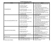
PM144J<br />
Winding 17<br />
THREE PHASE EFFICIENCY CURVES<br />
PER CENT TRANSIENT VOLTAGE DIP .<br />
30<br />
25<br />
20<br />
15<br />
10<br />
5<br />
APPROVED DOCUMENT<br />
Locked Rotor Motor Starting Curves<br />
AS480 AVR With EBS<br />
<strong>600</strong>V<br />
0<br />
0 20 40 60 80 100 120 140 160 180 200<br />
LOCKED ROTOR kVA<br />
4
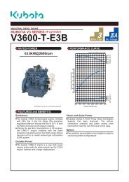
PM144J<br />
Winding 17<br />
Three-<strong>phase</strong> Short Circuit Decrement Curve. No-load Excitation at Rated Speed<br />
Based on star (wye) connection.<br />
1000<br />
SYMMETRICAL<br />
ASYMMETRICAL<br />
CURRENT (Amps)<br />
100<br />
Sustained Short Circuit = 180 Amps<br />
APPROVED DOCUMENT<br />
10<br />
0.001 0.01<br />
TIME (secs)<br />
0.1 1 10<br />
Note<br />
The following multiplication factor should be used to convert the values from curve for the<br />
various types of short circuit :<br />
3-<strong>phase</strong> 2-<strong>phase</strong> L-L 1-<strong>phase</strong> L-N<br />
Instantaneous<br />
x 1.00 x 0.87 x 1.30<br />
Minimum<br />
x 1.00 x 1.80 x 3.20<br />
Sustained<br />
x 1.00 x 1.50 x 2.50<br />
Max. sustained duration<br />
10 sec. 5 sec. 2 sec.<br />
All other times are unchanged<br />
5
PM144J<br />
Winding 17 / 0.8 <strong>Power</strong> Factor<br />
60Hz<br />
Class - Temp Rise<br />
Series Star (V)<br />
Parallel StarStar (V)<br />
Series Delta (V)<br />
kVA<br />
RATINGS<br />
Cont. E - 65/50°C Cont. B - 70/50°C Cont. F - 90/50°C Cont. H - 110/50°C<br />
<strong>600</strong><br />
300<br />
346<br />
34.0<br />
<strong>600</strong><br />
300<br />
346<br />
35.3<br />
<strong>600</strong><br />
300<br />
346<br />
40.0<br />
<strong>600</strong><br />
300<br />
346<br />
44.2<br />
kW<br />
27.2<br />
28.2<br />
32.0<br />
35.4<br />
Efficiency (%)<br />
89.7<br />
89.7<br />
89.5<br />
89.2<br />
kW Input<br />
30.3<br />
31.4<br />
35.8<br />
39.7<br />
APPROVED DOCUMENT<br />
DIMENSIONS<br />
6
APPROVED DOCUMENT<br />
Head Office Address:<br />
Barnack Road, Stamford<br />
Lincolnshire, PE9 2NB<br />
United Kingdom<br />
Tel: +44 (0) 1780 484000<br />
Fax: +44 (0) 1780 484100<br />
www.cumminsgeneratortechnologies.com<br />
Copyright 2010, Cummins Generator Technologies Ltd, All Rights Reserved<br />
Stamford and AvK are registered trade marks of Cummins Generator Technologies Ltd<br />
Cummins and the Cummins logo are registered trade marks of Cummins Inc.<br />
PM144J-17-TD-EN-SG-A