spindle nose a - Usinages
spindle nose a - Usinages
spindle nose a - Usinages

Create successful ePaper yourself
Turn your PDF publications into a flip-book with our unique Google optimized e-Paper software.
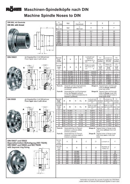
Maschinen-Spindelköpfe nach DIN<br />
Machine Spindle Noses to DIN<br />
DIN 800, mit Gewinde<br />
DIN 800, with thread<br />
A<br />
Tol. mittel<br />
A<br />
Mean tol.<br />
Bg5<br />
Bg5<br />
C<br />
Kleinstmaß<br />
C<br />
Minimum<br />
D E F<br />
D E F<br />
M20 21 30 6,3 10 20<br />
M24 25 36 8 12 24<br />
M33 34 50 9 14 30<br />
M39 40 56 10 16 35<br />
M45 46 67 11 18 40<br />
M52 55 80 12 20 45<br />
M60 62 90 14 22 50<br />
M76x6 78 112 16 30 63<br />
M105x6 106 150 20 40 80<br />
DIN 55021<br />
DIN 55026<br />
ab Kegelgröße 4 mit Mitnehmer<br />
From taper size 4 with driver<br />
ab Kegelgröße 4 mit Mitnehmer<br />
From taper size 4 with driver<br />
Spindel-<br />
kopf-<br />
Größe<br />
A B C D<br />
<strong>spindle</strong><br />
<strong>nose</strong><br />
A B C D<br />
size<br />
Lochzahl auf<br />
äußerem<br />
Lochkreis (F1)<br />
E1 G<br />
Holes on outer<br />
bolt circle (F1)<br />
E1 G<br />
F1 Lochzahl inn. F2<br />
(äußerer Lochkreis (innerer<br />
Lochkr.) (F2) E2 Lochkr.)<br />
F1<br />
(outer<br />
bolt<br />
circle)<br />
Holes on<br />
inner bolt<br />
circle<br />
(F2) E2<br />
F2<br />
(inner<br />
bolt<br />
circle)<br />
3 102 53,985 11 16 3xM10 3x10,5 75 — —<br />
4 112 63,525 11 20 3xM10 3x10,5 85 — —<br />
5 135 82,575 13 22 7xM10 4x10,5 104,8 8xM10 61,9<br />
6 170 106,390 14 25 7xM12 4x13 133,4 8xM12 82,6<br />
8 220 139,735 16 28 7xM16 4x17 171,4 8xM16 111,1<br />
11 290 196,885 18 35 12xM20 6x21 235 11xM20 165,1<br />
15 380 285,800 20 42 12xM24 6x25 330,2 11xM24 247,6<br />
20 520 412,800 21 48 12xM24 6x25 463,6 11xM24 368,3<br />
Form A:<br />
Form B:<br />
Gewinde und Durchgangslöcher<br />
im Flansch (ohne inneren<br />
Lochkreis)<br />
Gewindelöcher und Durchgangslöcher<br />
im Flansch (äußerer<br />
Lochkreis) und Gewindelöcher im<br />
inneren Lochkreis.<br />
Shape A: Tapped holes and throughholes<br />
in flange (without<br />
inner bolt circle)<br />
Shape B: Tapped holes and throughholes<br />
in flange (outer bolt<br />
circle) and tapped holes in<br />
inner bolt circle<br />
Spindel-<br />
kopf-<br />
A B C C 1 D<br />
Lochzahl äuß.<br />
Lochkreis (F1)<br />
F1<br />
(äußerer<br />
Lochzahl inn.<br />
Lochkreis (F2)<br />
F2<br />
(innerer<br />
Größe<br />
E1 Lochkr.) E2 Lochkr.)<br />
<strong>spindle</strong><br />
Holes on outer F1 Holes on inner F2<br />
<strong>nose</strong><br />
A B C C 1 D bolt circle (F1)<br />
(outer bolt<br />
bolt circle (F2)<br />
(inner bolt<br />
size<br />
E1 circle) E2 circle)<br />
3 92 53,983 11 — 16 3xM10 70,6 — —<br />
4 108 63,521 11 — 20 11xM10 82,6 — —<br />
5 133 82,573 13 14,288 22 11xM10 104,8 8xM10 61,9<br />
6 165 106,385 14 15,875 25 11xM12 133,4 8xM12 82,6<br />
8 210 139,731 16 17,462 28 11xM16 171,4 8xM16 111,1<br />
11 280 196,883 18 19,05 35 11xM20 235 8xM20 165,1<br />
15 380 285,791 19 20,638 42 12xM24 330,2 11 x M24 247,6<br />
20 520 412,795 21 22,225 48 12xM24 463,6 11 x M24 368,3<br />
Form A: Gewindelöcher im Flansch<br />
(äußerer Lochkreis) ohne<br />
inneren Lochkreis<br />
Form B:<br />
Gewindelöcher im Flansch<br />
(äußerer Lochkreis) und im<br />
inneren Lochkreis<br />
Shape A: Tapped holes in flange (outer<br />
bolt circle) without inner bolt<br />
circle<br />
Shape B: Tapped holes in flange (outer<br />
bolt circle) and in inner bolt<br />
circle<br />
DIN 55027 und 55022<br />
Bajonettscheiben-Befestigung g (ISO 702/III)<br />
DIN 55027 and 55022 and ISO 702/III<br />
with bayonet ring fixing<br />
Spindel-<br />
kopf-<br />
Größe<br />
<strong>spindle</strong><br />
<strong>nose</strong><br />
size<br />
A B C D Lochzahl x E F<br />
A B C D<br />
Number of<br />
holes x E<br />
3 102 53,985 11 16 3 x 21 75<br />
4 112 63,525 11 20 3 x 21 85<br />
5 135 82,575 13 22 4 x 21 104,8<br />
6 170 106,390 14 25 4 x 23 133,4<br />
8 220 139,735 16 28 4 x 29 171,4<br />
11 290 196,885 18 35 6 x 36 235<br />
15 400 285,800 19 42 6 x 43 330,2<br />
20 540 412,800 21 48 6 x 43 463,6<br />
F<br />
Verbindlich ist jeweils die neueste Ausgabe des DIN-Blatts.<br />
Latest edition of relevant DIN standard applies in each case.
SPINDLE NOSE A<br />
American Standard<br />
Type A1, A2, B1, B2.<br />
USAS B5.9-1967<br />
(ISO 702/I)<br />
(DIN 55021)<br />
(DIN 55026)<br />
A1<br />
A2<br />
B1<br />
B2<br />
Has tapped holes on both the outer and the inner bolt circles.<br />
Has tapped holes on the outer bolt circle, but has no holes on the inner bolt circle.<br />
Has drilled holes on the outer bolt circle, and tapped holes on the inner bolt circle<br />
Has drilled holes on the outer bolt circle, but has no holes on the inner bolt circle.<br />
Dimensions (mm)<br />
Spindle Nose Measuring 3” 4” 5” 6” 8” 11” 15” 20” 28”<br />
Dia of <strong>spindle</strong> A 92 108 133 165 210 280 380 520 725<br />
Pilot Dia max B 53,975 63,513 82,563 106,375 139,719 196,869 285,775 412,775 584,225<br />
Length of pilot (A1, B1) C - - 14,288 15,875 17,462 19,05 20,638 22,225 25,4<br />
Length of pilot (A2, B2) C 11,113 11,113 12,7 14,288 15,875 17,463 19,05 20,638 23,813<br />
Radius inner bolt circle D - - 30,955 41,275 55,563 82,55 123,825 184,15 265,113<br />
Radius outer bolt circle E 35,331 41,275 52,388 66,675 85,725 117,475 165,1 231,775 323,85<br />
Dia of driving button F - 14,288 15,875 19,05 23,813 28,575 34,925 41,275 50,8<br />
Angle to driving button - 30° 30° 30° 30° 30° 15° 15° 15°<br />
Screw (A1, A2, B1) UNC 7/16” UNC 7/16” UNC 7/16” UNC 1/2” UNC 5/8” UNC 3/4” UNC 7/8” UNC 1” UNC 1-1/4”<br />
M10 M10 M10 M12 M16 M20 (M18) M24 (M22) M24 M30<br />
Dia bolt hole (B1, B2) 11,9 11,9 11,9 13,5 16,7 20,2 23,4 26,6 32,9<br />
Full depth thread 15,9 19 19 22,2 27 31,7 36,5 41,3 50,8<br />
Number of holes (outer) 3 1 1 1 1 1 1 1 1 1 1 1 2 1 2 1 2<br />
Number of holes (inner) - - 8 8 8 8 1 1 1 1 1 1<br />
Remark! 3” <strong>nose</strong> is without driving button.<br />
100
SPINDLE NOSE D<br />
American Standard<br />
Type D1.<br />
USAS B5.9-1967<br />
ISO 702/II<br />
(DIN 55029)<br />
This <strong>spindle</strong> <strong>nose</strong> is provided with a short tapered flange of the same dimensions<br />
as type A, but has in its face a number of holes (3 or 6) into which the lock studs<br />
of the chuck can be inserted. By turning eccentric the chuck is pressed towards the<br />
cone of the <strong>spindle</strong> and is locked.<br />
Dimensions (mm)<br />
Spindle Nose Dimension 3” 4” 5” 6” 8” 11” 15” 20”<br />
Dia of <strong>spindle</strong> A 92 117 146 181 225 298 403 546<br />
Pilot Dia max B 53,975 63,513 82,563 106,375 139,719 196,869 285,775 412,775<br />
Length of pilot C 11,113 11,113 12,7 14,288 15,875 17,463 19,05 20,638<br />
Radius of holes E 35,331 41,275 52,388 66,675 85,725 117,475 165,1 231,775<br />
Dia of holes F 15,1 16,7 19,8 23 26,2 31 35,7 42,1<br />
Number of holes 3 3 6 6 6 6 6 6<br />
101
SPINDLE NOSE DIN<br />
German Standard<br />
Type DIN.<br />
DIN 55027<br />
(ISO 702/III)<br />
This <strong>spindle</strong> <strong>nose</strong> is provided with a short tapered flange like the americane <strong>spindle</strong> <strong>nose</strong>s.<br />
In its face this <strong>spindle</strong> <strong>nose</strong> has a number of holes (3,4 or 6), into which the<br />
lock studs of the chuck can be inserted. The locking is made by a bayonet clutch.<br />
Dimensions (mm)<br />
Spindle <strong>nose</strong> Dimension 3” 4” 5” 6” 8” 11” 15” 20”<br />
Dia of <strong>spindle</strong> A 102 112 135 170 220 290 400 540<br />
Pilot Dia max B 53,983 63,521 82,573 106,385 139,731 196,883 285,791 412,795<br />
Length of pilot C 11 11 13 14 16 18 19 21<br />
Dia of driving button F - 14,25 15,9 19,05 23,8 28,6 34,9 41,3<br />
Radius of holes E 37,5 42,5 52,4 66,7 85,7 117,5 165,1 231,8<br />
Dia of hole G 21 21 21 23 29 36 43 43<br />
Thread on lock studs M10 M10 M10 M12 M16 M20 M24 M24<br />
Number of holes 3 3 4 4 4 6 6 6<br />
102
SPINDLE NOSE L<br />
American Standard<br />
Type L.<br />
USAS B5.9-1967<br />
This <strong>spindle</strong> <strong>nose</strong> is provided with a long, steep taper for locating and centering<br />
the chuck. A driving key and a flanged nut hold the chuck on the <strong>spindle</strong>.<br />
Dimensions (mm)<br />
Spindle Nose Dimension L-00 L-0 L-1 L-2 L-3<br />
Thread in flange nut A 3 3 /4”-6 Unified 4 1 /2”-6 Unified 6”-6 Unified 7 3 /4”-5 Unified 10 3 /8”-4 Unified<br />
Form - Special Form - Special Form - Special Form - Special Form - Special<br />
Mesh length of thread C 16,67 17,46 19,05 25,4 26,99<br />
Dia pilot max B 69,85 82,55 104,775 133,35 165,1<br />
Length of pilot D 50,8 60,325 73,025 85,725 98,425<br />
Driving key (L x B x H) 38,1 x 9,52 x 9,52 44,45 x 9,52 x 9,52 60,32 x 15,87 x 15,8773,02 x 19,05 x 19,0582,55 x 25,4 x 25,4<br />
103