Infrared Radiometer - Apogee Instruments
Infrared Radiometer - Apogee Instruments
Infrared Radiometer - Apogee Instruments

You also want an ePaper? Increase the reach of your titles
YUMPU automatically turns print PDFs into web optimized ePapers that Google loves.
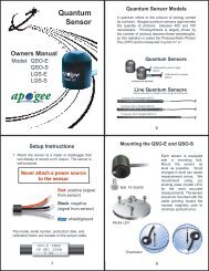
Owners Manual<br />
Model: IRR-P<br />
IRR-PN<br />
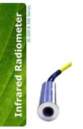
<strong>Infrared</strong><br />
<strong>Radiometer</strong><br />
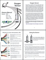
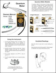
Wiring Diagram for IRR-P and IRR-PN<br />
Red<br />
Black<br />
Clear<br />
Green<br />
Blue<br />
White<br />
High side of differential<br />
channel (positive<br />
thermopile lead)<br />
Low side of differential<br />
channel (negative<br />
thermopile lead)<br />
Analog ground<br />
(thermopile ground)<br />
Single-ended channel<br />
(positive thermistor lead)<br />
Analog ground (negative<br />
thermistor lead)<br />
Excitation channel<br />
(excitation for thermistor)<br />
sample programming and instructions<br />
available online:<br />
www.apogee-inst.com/programs<br />
1<br />
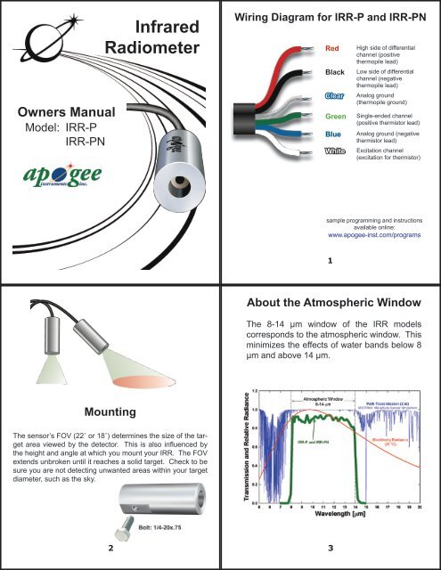
About the Atmospheric Window<br />
The 8-14 µm window of the IRR models<br />
corresponds to the atmospheric window. This<br />
minimizes the effects of water bands below 8<br />
µm and above 14 µm.<br />
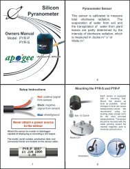
Mounting<br />
The sensor’s FOV (22˚ or 18˚) determines the size of the target<br />
area viewed by the detector. This is also influenced by<br />
the height and angle at which you mount your IRR. The FOV<br />
extends unbroken until it reaches a solid target. Check to be<br />
sure you are not detecting unwanted areas within your target<br />
diameter, such as the sky.<br />
2 3
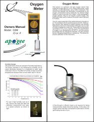
Accuracy and Calibration<br />
During calibration the sensor body temperature ranges from<br />
-5 to 45 ˚C at 10 ˚C increments. At each step the target<br />
temperature ranges from +20 to -15 ˚C relative to the sensor<br />
body temperature.<br />
The output of IRR sensors follows the fundamental physics of<br />
the Stefan-Boltzmann Law, which states that radiation transfer<br />
is proportional to temperature raised to the fourth power (T 4 ). A<br />
version of the S-B equation proposed by Kalma et al. (Calibration<br />
of small infra-red surface temperature transducers, Ag. For.<br />
Met., 1988) is used to calibrate the sensors taking into account<br />
the effect of sensor body temperature (see graph shown aboveright):<br />
T T<br />
4<br />
- T D<br />
4<br />
= m • mV + b<br />
The graph below shows the residual error (T MT<br />
– T BB<br />
) where<br />
T MT<br />
is measured temperature and T BB<br />
is blackbody temperature).<br />
where T T<br />
[K] is the target temperature (blackbody cone<br />
temperature during calibration), T D<br />
[K] is the detector<br />
temperature, mV is the millivolt output of the detector and<br />
serves as a surrogate for emitted energy, m is the slope and<br />
b is the intercept. The coefficients m and b are derived during<br />
sensor calibration and are functions of the detector temperature.<br />
To make temperature measurements, the equation can be<br />
rearranged to solve for T T<br />
, which is calculated from the<br />
measured values of T D<br />
and mV, and the calculated values of m<br />
and b (calculated from T D<br />
):<br />
4 5<br />
4<br />
T T<br />
= (T D<br />
+ m • mV + b) 1/4 Precision (IRR-P) Precision Narrow (IRR-PN)<br />
Field of View<br />
Specifications<br />
Field of View (FOV) is reported as the halfangle<br />
of the apex of the cone formed by the target<br />
(cone base) and the detector (cone apex). The<br />
target is a circle from which 98% of the radiation<br />
being viewed by the detector is being emitted.<br />
Model IRR-P half-angle = 22.0˚<br />
Model IRR-PN half-angle = 18.0˚<br />
Field of view 22° half angle 18° half angle<br />
Output Target temp. 60 µV per °C difference<br />
from sensor body<br />
Sensor body temp. 0-2500 mV 0-2500 mV<br />
Accuracy -10 to 65 °C ±0.2 °C absolute accuracy<br />
Optics<br />
Wavelength range<br />
Response time<br />
Input power<br />
Operating environment<br />
Datalogger channels<br />
Cable<br />
Dimensions<br />
Mass<br />
Warranty<br />
±0.1 °C uniformity<br />
±0.05 °C repeatability<br />
-40 to 70 °C ±0.5 °C absolute accuracy<br />
±0.3 °C uniformity<br />
±0.1 °C repeatability and uniformity<br />
Germanium lens<br />
40 µV per °C difference<br />
from sensor body<br />
8-14 µm (corresponds to atmospheric window)<br />
< 1 second to changes in target temperature<br />
2.5 V excitation<br />
-55 to 80 °C; 0 to 100 % RH (non-condensing)<br />
Water resistant, designed for continuous outdoor use<br />
1 differential (detector) and 1 single-ended (thermistor)<br />
4.5 meters twisted, shielded 4 conductor wire with<br />
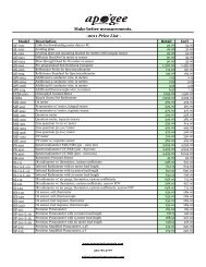
Santoprene casing. Extra cable $ 2.95 per meter.<br />
6 cm long by 2.3 cm diameter<br />
190 g<br />
1 year parts and labor<br />
6<br />
435-792-4700<br />
www.apogeeinstruments.com<br />
techsupport@apogee-inst.com