6054012BR01 FMX ENG - Moeller
6054012BR01 FMX ENG - Moeller
6054012BR01 FMX ENG - Moeller

You also want an ePaper? Increase the reach of your titles
YUMPU automatically turns print PDFs into web optimized ePapers that Google loves.
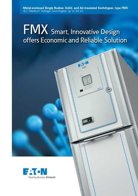
Metal-enclosed Single Busbar, Solid- and Air-insulated Switchgear, type <strong>FMX</strong><br />
IEC Medium Voltage Switchgear up to 24 kV<br />
<strong>FMX</strong> Smart, Innovative Design<br />
offers Economic and Reliable Solution
Automotive<br />
Powering<br />
business<br />
worldwide<br />
Aerospace<br />
Eaton delivers the power inside hundreds of products that<br />
are answering the demands of today’s fast changing world.<br />
We help our customers worldwide manage the power<br />
they need for buildings, aircraft, trucks, cars, machinery<br />
and entire businesses. And we do it in a way that<br />
consumes fewer resources.<br />
Truck<br />
Hydraulics<br />
Next generation<br />
transportation<br />
Eaton is driving the<br />
development of new<br />
technologies – from hybrid<br />
drivetrains and emission control<br />
systems to advanced engine<br />
components – that reduce fuel<br />
consumption and emissions in<br />
trucks and cars.<br />
Higher expectations<br />
We continue to expand our<br />
aerospace solutions and<br />
services to meet the needs of<br />
new aviation platforms,<br />
including the high-flying light jet<br />
and very light jet markets.<br />
Building on our strengths<br />
Our hydraulics business<br />
combines localised service and<br />
support with an innovative<br />
portfolio of fluid power<br />
solutions to answer the needs<br />
of global infrastructure projects,<br />
including locks, canals and<br />
dams.<br />
Powering Greener Buildings<br />
and Businesses<br />
Eaton’s Electrical Group is a<br />
leading provider of power<br />
quality, distribution and control<br />
solutions that increase energy<br />
efficiency and improve power<br />
quality, safety and reliability.<br />
Our solutions offer a growing<br />
portfolio of “green” products<br />
and services, such as energy<br />
audits and real-time energy<br />
consumption monitoring.<br />
Eaton’s Uninterruptible Power<br />
Supplies (UPS), variable-speed<br />
drives and lighting controls help<br />
conserve energy and increase<br />
efficiency.<br />
Electrical Hydraulics<br />
2
MV Switchgear Technology<br />
is in our DNA<br />
Eaton’s knowledge and understanding of industries, applications,<br />
technology and products enables us to offer customers safe,<br />
reliable and high performance solutions. We have been part of the<br />
Medium Voltage switchgear technology creation and therefore<br />
carry what’s needed with us – always!<br />
Complete MV switchgear solutions<br />
The series of Eaton Medium Voltage systems offers switchgear<br />
and components for applications in distribution networks (sub -<br />
stations and transformer stations) and industrial power supplies.<br />
These technically high quality systems are air- or epoxy-resin<br />
insulated and are always equipped with circuit-breakers based on<br />
proprietary vacuum interrupters.<br />
The medium voltage switchgear systems carrying Eaton’s brand<br />
are based on the use of vacuum circuit-breakers combined with<br />
solid insulation material. This is an environmentally-friendly<br />
technology in comparison with the methods used by many other<br />
suppliers, which use SF6 as an insulation medium.<br />
Eaton thus has a wide range of switching systems and<br />
components that offer an environmentally friendly solution for<br />
every application. Additionally, Eaton’s global service network<br />
provides maximum customer support in all regions of the world.<br />
Industry leading vacuum and solid insulation technology<br />
Through more than eighty years of innovation and experience,<br />
Eaton has developed environmentally friendly vacuum interrupters<br />
capable of reliably switching both normal load currents and high<br />
stress fault currents.<br />
Eaton is one of the few companies in the world producing vacuum<br />
interrupters and has succeeded in developing world class products<br />
with a number of international patents. This has been achieved<br />
through company acquisitions over the years of Westinghouse,<br />
Cutler-Hammer, MEM and Holec.<br />
Eaton’s range of<br />
SF6 free switchgear<br />
for Medium Voltage<br />
To increase the dielectric strength of the vacuum interrupter,<br />
Eaton has also designed vacuum interrupters that are encapsulated<br />
in epoxy resin material. The medium voltage IEC circuit breaker<br />
family utilizes this solid insulation technology that has been<br />
catering to a wide range of applications for more than 40 years.<br />
3
<strong>FMX</strong> Smart, Innovative Design<br />
offers Economic and Reliable Solution<br />
Type <strong>FMX</strong> is Eaton's IEC single busbar, solid- and airinsulated<br />
medium voltage switchgear system, for use up<br />
to 24 kV. The system provides reliable switching,<br />
protection, metering and distribution of electrical energy.<br />
The modern design system<br />
uses Eaton's state of the art<br />
technology and is manufactured<br />
in accordance with the highest<br />
quality standards. Within the<br />
system our engineers have<br />
integrated Eaton core<br />
technologies, such as vacuum<br />
technology, solid insulation and<br />
electrical field control. More<br />
than a century of experience in<br />
design and production of<br />
medium voltage systems has<br />
gone into the product.<br />
Type <strong>FMX</strong> switchgear features<br />
a reliable and compact system<br />
design, which benefits from<br />
the best practices incorporated<br />
in Eaton's current range of<br />
MV systems. The system is<br />
tested according the latest<br />
standard IEC 62271.<br />
The system uses only<br />
environmentally friendly<br />
technology and materials.<br />
Since the type <strong>FMX</strong> system<br />
is based on vacuum technology<br />
and solid insulation, the system<br />
is the latest environmentally<br />
friendly "green" switchgear on<br />
the market.<br />
The new system incorporates<br />
highly innovative technology,<br />
by implementing an electro -<br />
magnetic mechanism for the<br />
circuit-breaker control, and it<br />
introduces an integrated cable<br />
test facility outside of the high<br />
voltage compartment.<br />
Complete Range up to 2000 A<br />
The <strong>FMX</strong> comprises a complete<br />
range up to 2000 A, with metalenclosed<br />
modular compact<br />
panels of a minimal 500 mm<br />
width. Both the 12 and 24 kV<br />
versions use the same compact<br />
housing.<br />
<strong>FMX</strong> completes the range of<br />
Eaton medium voltage switch -<br />
gear, being an extension to the<br />
successful products MMS<br />
(double busbar), Unitole (with-<br />
drawable switchgear), SVS<br />
(single busbar secondary switch -<br />
gear) and Xiria (ring main unit).<br />
In combination with Eaton's low<br />
voltage switchgear, busbar<br />
trunking, UPS products, project<br />
management and service<br />
capabilities, the <strong>FMX</strong> can be part<br />
of a state of the art, complete<br />
solution.<br />
Application Areas<br />
The <strong>FMX</strong> is ideally suited for<br />
applications in main feeder<br />
stations, sub-distribution<br />
stations and specific customer<br />
requirements in (process)<br />
industry, commercial and<br />
governmental buildings and<br />
infrastructure projects.<br />
The design makes the <strong>FMX</strong><br />
system especially suitable for<br />
applications where a reliable,<br />
safe, economic (e.g. compact)<br />
and clean (e.g. non-toxic)<br />
environment is necessary.<br />
Some applications are:<br />
• Utilities (main- and subdistribution<br />
stations)<br />
• Commercial and<br />
governmental buildings<br />
• Infrastructure projects<br />
(tunnels, subways,<br />
airports, etc.)<br />
• Hospitals<br />
• Process industry<br />
• Cement industry<br />
• Mining industry<br />
• Automotive industry<br />
• Petrochemical plants<br />
• Textile and paper industry<br />
• Food industry<br />
• Data centres<br />
4
Features and Benefits<br />
(quick overview)<br />
Safe in Use<br />
• Compartments protected<br />
against penetration by<br />
objects<br />
• Capacitive voltage detection<br />
system for verification of<br />
safe isolation from supply<br />
• Operation only possible with<br />
closed cable compartment<br />
• Logical mechanical and<br />
electrical interlocks prevent<br />
mal-operation<br />
• Cable testing via integrated<br />
cable test facility outside<br />
high voltage compartments<br />
• Voltage transformers can be<br />
(dis)connected from the<br />
primary circuit, with closed<br />
high voltage compartments<br />
• Smooth contemporary<br />
design<br />
Low Total Cost of Ownership<br />
Low initial costs due to:<br />
• Panels only 500 mm width<br />
• Cable connection from the<br />
front (back to wall<br />
arrangement)<br />
• Integrated arc channel with<br />
absorbers<br />
• 12 kV and 24 kV panels in<br />
the same housing<br />
No costs during service due to:<br />
• Robust design with a<br />
minimum number of parts<br />
(routine tested in factory)<br />
• Long-life, using epoxy resin<br />
as insulation medium<br />
• Maintenance-free circuitbreaker<br />
(electromagnetic<br />
mechanism and vacuum<br />
interrupters)<br />
• No SF6 pressure checks<br />
Low end of life disposal cost<br />
due to:<br />
• Vacuum switching<br />
technology<br />
• Solid insulation with air as<br />
insulating medium<br />
• Recycling or re-use of<br />
materials<br />
User Friendly<br />
• Cable connection and user<br />
interfaces for operation on<br />
the same side of the unit<br />
• Ergonomic cable connection<br />
height of 750 mm from floor<br />
level<br />
• Different cable cone lengths<br />
for easy cable connection<br />
• Cable (secondary) entry<br />
points on both sides of the<br />
low voltage compartment<br />
top plate<br />
• Secondary cable terminals<br />
positioned at a good<br />
reachable height within the<br />
low voltage compartment<br />
• Clear and simple,<br />
straightforward operation<br />
panels<br />
• Facility for (dis)connecting<br />
the voltage transformers,<br />
easily accessible from the<br />
front without entering the<br />
HV compartment<br />
• Integrated cable test facility<br />
positioned on the manual<br />
operation panel<br />
Environmentally Friendly<br />
• Minimised number of<br />
components<br />
• Environmentally-friendly<br />
materials used in the design<br />
• No use of SF6-gas for<br />
switching and insulation<br />
(green switching)<br />
• Energy-efficient production<br />
and assembly, with<br />
environmentally friendly<br />
energy sources<br />
• Minimal number of<br />
transition points in the<br />
primary design enables low<br />
energy loss during operation<br />
• Only re-usable and/or<br />
recyclable materials used<br />
Reliable and Safe in<br />
Operation<br />
• Complete design certified<br />
in accordance with IEC<br />
• Arc fault tested in<br />
accordance with<br />
IEC 62271-200<br />
• Quality assurance in<br />
accordance with<br />
DIN EN 9001<br />
• Routine tested<br />
• Single pole insulated primary<br />
parts within one<br />
compartment<br />
• Separate busbar<br />
compartment<br />
• Integrated cable test facility<br />
• Ferro resonance protected<br />
voltage transformers<br />
• Integrated arc absorbers<br />
5
Basic Design<br />
The <strong>FMX</strong> system is<br />
modular in construction.<br />
This ensures that any<br />
panel combination and<br />
sequence is possible.<br />
In addition, the number of panels capable of being used in<br />
an installation is unlimited, as several sections can easily be<br />
connected. The panels in the <strong>FMX</strong> system are compact<br />
(min. 500 mm wide), resulting in considerable savings in<br />
costs and installation space.<br />
1<br />
2<br />
3<br />
4<br />
5<br />
6<br />
13<br />
7<br />
8 14<br />
15<br />
9<br />
10<br />
11<br />
16<br />
17<br />
12<br />
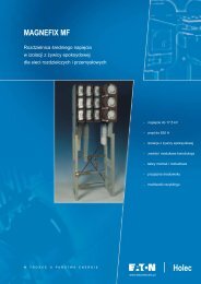
Circuit-breaker panel (example)<br />
1. Protection relay<br />
2. Arc absorber<br />
3. Mimic diagram with push<br />
buttons for operation of<br />
circuit-breaker and changeover<br />
switch<br />
4. Busbar<br />
5. Voltage detection system<br />
6. Change-over switch<br />
7. Vacuum interrupter<br />
8. Manual operation panel<br />
with position indicator<br />
9. Current transformers<br />
10. Cable cones<br />
11. Coil and resistor for<br />
protection against<br />
ferro-resonance<br />
12. Voltage transformers<br />
13. Low voltage compartment<br />
(electrical control panel)<br />
14. Vacuum circuit-breaker<br />
with electromagnetic<br />
mechanism<br />
15. Cable test facility<br />
16. Cable clamps<br />
17. Earth bar<br />
6
Main Components<br />
Vacuum circuit-breaker<br />
The vacuum circuit-breaker uses a simple and reliable<br />
electromagnetic mechanism for operation of the vacuum<br />
interrupters. The construction of the mechanical linkage between<br />
the actuator and the drive rod of each of the three vacuum<br />
interrupters is simple, compared to a conventional spring-charged<br />
mechanism.<br />
Features<br />
• Environmentally friendly vacuum interrupters<br />
• Electromagnetic mechanism with controller<br />
• Mechanical lever for hand-operated operation<br />
• Mechanical position indicator for Open / Closed position<br />
• Auxiliary contacts for Open / Closed position<br />
Two-position change-over switch<br />
All panels are equipped with a change-over switch consisting of<br />
interconnected contact pins moving in the horizontal plane. Since<br />
it is mechanically interlocked, the change-over switch can only be<br />
operated when the circuit-breaker is in the open position.<br />
Features<br />
• Motor or manually-operated switch with two positions<br />
(Service / Earthed)<br />
• Interconnected contact pins moving in the horizontal plane<br />
• Contact pins epoxy resin insulated and located in the busbar<br />
compartment<br />
• Auxiliary contacts for Service / Earthed positions<br />
• Mechanical position indicators<br />
• Interlocked with the vacuum circuit-breaker<br />
Busbars<br />
The busbars in the panel are constructed from high-quality aluminium<br />
bars of standardised cross-sections. The shape of the busbar has<br />
been designed to attain optimal electrical field control.<br />
Features<br />
• Busbars constructed from high-quality aluminium<br />
• Branch of busbars made of copper or aluminium<br />
• Aluminium parts coated with galvanic silver layer<br />
• Housed in busbar duct covering the full width of the panel<br />
• Air insulated<br />
• Situated in compartment complying with IP4X degree<br />
of protection<br />
7
Eaton Core Technologies<br />
Solid insulation using cast resin technology<br />
Epoxy resin (cast resin) is used<br />
as high-quality primary solid<br />
insulation material around live<br />
parts.<br />
By using cast resin technology<br />
for solid insulation, Eaton<br />
design engineers can shape the<br />
parts specifically for optimal<br />
insulation, robust construction<br />
and cooling purposes.<br />
With many years of experience<br />
of design and manufacture of<br />
epoxy resin insulated<br />
components, we have learned<br />
to integrate conductors and<br />
vacuum interrupters directly<br />
into the moulding, and to<br />
make complex shapes. <strong>FMX</strong><br />
utilises optimal field control<br />
through the special design of<br />
all primary components.<br />
Electrical Field control<br />
With conventional shapes for<br />
primary components like<br />
busbars and conductors, the<br />
electrical field between the<br />
phases, and between phases<br />
and earth, is non-uniformly<br />
distributed. In areas with high<br />
fields, partial break-through can<br />
trigger avalanches resulting in<br />
flash-overs. In-depth<br />
knowledge of breakthrough<br />
phenomena and field steering<br />
techniques enables us to<br />
prevent flash-over completely.<br />
The result is a particularly<br />
compact design.<br />
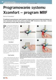
Vacuum technology: safe, compact and reliable<br />
Eaton vacuum interrupters<br />
consist of a ceramic cylinder,<br />
housing a fixed and movable<br />
contact. Movement of the<br />
contact under vacuum<br />
conditions is performed by<br />
bellows. A shield surrounding<br />
the contacts prevents the<br />
insulators from becoming<br />
contaminated by metal vapour<br />
produced during current<br />
interruption. This shield also<br />
ensures good potential<br />
distribution over the insulator.<br />
A special feature of Eaton<br />
vacuum interrupters is that a<br />
large number of parallel arcs<br />
are created between the<br />
contacts. This "diffuse<br />
discharge" is characterised by<br />
very low arc voltage and short<br />
arc times, resulting in very low<br />
arc energy. Contact wear in a<br />
vacuum interrupter is therefore<br />
virtually negligible. Vacuum<br />
interrupters are maintenance<br />
free and are certified up to<br />
30,000 operation cycles<br />
1<br />
2 4<br />
3<br />
1. Bellows<br />
2. Bellows shield<br />
3. Ceramic insulators<br />
4. Movable contact<br />
5. Magnetic laminations<br />
5<br />
8
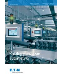
Innovative Electromagnetic Mechanism<br />
The advantage of an electromagnetic mechanism<br />
over a conventional spring operated mechanism<br />
To switch a vacuum interrupter<br />
effectively, the driving<br />
mechanism has to operate<br />
according to a specific forcestroke<br />
characteristic (-), see<br />
the diagram.<br />
Force (N)<br />
Stroke (mm)<br />
Force-stroke characteristics<br />
- as required by vacuum switch<br />
- as offered by a conventional<br />
spring operated mechanism<br />
- as offered by an<br />
electromagnetic mechanism<br />
A conventional, spring operated<br />
mechanism has force-stroke<br />
characteristics (-) that differ<br />
greatly from the required<br />
characteristics. The required<br />
force-stroke diagram therefore<br />
has to be transferred from the<br />
spring characteristics, leading<br />
to mechanisms that require a<br />
large number of links moving at<br />
high speed.<br />
An electromagnetic mechanism<br />
has a stroke diagram (-) that<br />
already resembles the forcestroke<br />
characteristic that is<br />
required for vacuum<br />
switchgear. Therefore<br />
electromagnetic mechanisms<br />
can be very simple in their<br />
construction. They consist of a<br />
minimum amount of parts and<br />
can be coupled directly to the<br />
vacuum interrupter, because of<br />
the favorable force-stroke<br />
characteristics. Due to this<br />
direct coupling maximum<br />
rigidity is reached, which is<br />
advantageous for the rate at<br />
which contact pressure is<br />
reached and the effectiveness<br />
of contact breaking.<br />
To sum up, the electromagnetic<br />
mechanism has the following<br />
advantages:<br />
• Superior reliability due to use<br />
of less parts and direct drive<br />
with high rigidity<br />
• Cost effective, maintenance<br />
free and compact due to the<br />
low number of parts<br />
• High number of switching<br />
cycles<br />
Innovative Electromagnetic Mechanism in <strong>FMX</strong> switchgear<br />
Eaton's electromagnetic mechanism is based on the idea<br />
of separating the magnetic circuits for closing, holding<br />
and opening.<br />
The mechanism consists of a permanent magnetic actuator and<br />
the basic mechanism in which a drive rod is connected to the<br />
vacuum interrupter. The permanent actuator is mono-stable; only<br />
the closed position is maintained by permanent magnets. The end<br />
position for opening, and therefore the stroke of the actuator, can<br />
be chosen at random within certain limits. For this innovative<br />
concept, a patent has been granted.<br />
Air gap<br />
Holding plate<br />
Plunger<br />
Trip coil<br />
Permanent magnet<br />
Yoke (mild steel)<br />
Closing coil<br />
Drive rod<br />
The standard position of the<br />
plunger is in the upper position.<br />
In this position the circuitbreaker<br />
is in the open position.<br />
Closing<br />
To close the circuit-breaker, the<br />
closing coil is energised. The<br />
current creates a magnetic flux<br />
in the yoke, which forces the<br />
plunger down. The force on the<br />
plunger is directly proportional<br />
to this current. When the force<br />
on the plunger becomes<br />
greater than the counteracting<br />
forces of the opening spring,<br />
friction, etc., the closing<br />
movement starts. When<br />
closed, the drive rod is kept in<br />
position by permanent<br />
magnets.<br />
Opening / tripping<br />
Opening is basically a passive<br />
action: the energy stored in the<br />
contact pressure spring and the<br />
opening spring is released. The<br />
release of this energy can be<br />
occasioned by an integrated<br />
trip coil, or a mechanical lever.<br />
Tripping (opening) the circuitbreaker<br />
is done by energising<br />
the tripping coil. By this, the<br />
magnetic flux of the permanent<br />
magnet is partly compensated.<br />
As soon as the holding force of<br />
the permanent magnet is less<br />
than that of the contact<br />
pressure spring, the plunger<br />
will move to the upper position,<br />
consequently opening the<br />
contacts in the vacuum<br />
interrupters. Due to the force in<br />
the contact pressure spring,<br />
the required energy for tripping<br />
is very low compared to closing<br />
the breaker.<br />
9
Reliable and Safe in Operation<br />
Eaton's proven technologies<br />
have been integrated in the<br />
design and development of<br />
the <strong>FMX</strong> in order to ensure<br />
that the switchgear is safe<br />
and has high operational<br />
reliability throughout its<br />
complete lifetime.<br />
Experience and knowledge<br />
gained over many years in the<br />
areas of cast resin technology,<br />
vacuum technology and<br />
electrical field control have<br />
been implemented.<br />
The system has been<br />
thoroughly arc fault tested<br />
according to the latest standard<br />
IEC 62271-200.<br />
Preventing an Internal Arc<br />
Within the <strong>FMX</strong> design, different technologies are used to prevent an internal arc.<br />
Use of electrical field control<br />
Engineers designed the busbar<br />
compartment and its components<br />
(e.g. busbars, conductors) based<br />
on Eaton's key technology for<br />
electrical field control. By means<br />
of special shapes and dimensions,<br />
the possibility of an internal arc is<br />
minimised.<br />
Protected voltage<br />
transformers<br />
Ferro-resonance causes<br />
damage to voltage<br />
transformers and<br />
consequently initiates an<br />
internal arc in the<br />
switchgear. The design<br />
prevents the voltage<br />
transformers from being<br />
affected by ferro-resonance<br />
by installing a resistor and<br />
a coil in the tertiary circuit<br />
of the voltage transformer.<br />
Separated busbar<br />
compartment<br />
The <strong>FMX</strong> has a separate busbar<br />
compartment to prevent an<br />
internal arc. This compartment<br />
can be classified as nonaccessible<br />
and has an IP rating<br />
of IP4X.<br />
Coupling the busbar and<br />
constructing the compartment<br />
on site will be carried out by<br />
specially trained service<br />
personnel.<br />
Single pole insulated primary parts<br />
All high voltage parts in accessible<br />
compartments are single pole insulated.<br />
The insulation material used for this is<br />
epoxy resin (cast resin), a high-quality<br />
material with optimal insulation<br />
characteristic resulting in minimised<br />
dimensions.<br />
Integrated cable test facility<br />
Internal arcs due to bad cable<br />
connections are becoming<br />
fewer, however they still<br />
occur. Therefore cables are<br />
tested before going live.<br />
The <strong>FMX</strong> is equipped with an<br />
integrated cable test facility.<br />
This eliminates the need to<br />
remove covers and disturb<br />
cable connections therefore<br />
reducing risk of incorrect reinstallations<br />
of cable<br />
connectors or covers.<br />
10
Routine tests<br />
Various routine tests are carried<br />
out during the production of the<br />
switchgear. To assure quality, all<br />
processes are in accordance<br />
with DIN EN 9001. This means<br />
that at every stage of<br />
production the components,<br />
circuit-breakers and current<br />
transformers are inspected for<br />
correct functioning. When the<br />
entire installation has been<br />
assembled, a thorough visual<br />
inspection is carried out,<br />
together with mechanical,<br />
functional and electrical checks.<br />
Philosophy on Internal arcs<br />
Eaton always puts extra focus<br />
on creating safe switchgear for<br />
operators at all times. One of<br />
the biggest potential threats to<br />
operators is an internal arc in<br />
switchgear.<br />
Engineers therefore did<br />
everything necessary in design<br />
and construction to prevent<br />
internal arcs, despite the fact<br />
that it is very rare for an<br />
operator to be in front (without<br />
operating) of the switchgear at<br />
exactly the same time that an<br />
internal fault occurs.<br />
Eaton supports the philosophy<br />
that it is best to avoid internal<br />
arcs than to cure, in line with<br />
the relevant standard<br />
IEC 62271-200. Within the <strong>FMX</strong><br />
design a double prevention<br />
philosophy is used. Firstly, the<br />
design is constructed in such a<br />
way that an internal arc is<br />
prevented. In the unlikely case<br />
that an internal arc could occur,<br />
the <strong>FMX</strong> is equipped to provide<br />
maximum safety to the<br />
operator, and to control and<br />
minimise damage to the rest of<br />
the switchgear and room.<br />
Controlling an Internal Arc<br />
An internal arc in switchgear causes an overpressure, together with the release of fire and smoke.<br />
By design, vacuum and air/solid<br />
insulated switchgear has the<br />
least environmental impact<br />
after an internal arc event.<br />
The impact of an arc is twofold:<br />
internal impact (in the switch -<br />
gear) and external impact (in<br />
the switch room).<br />
The overpressure created by an<br />
internal arc will, in standard<br />
switchgear, be channeled out<br />
of the switchgear by means of<br />
a pressure relief duct. This duct<br />
is normally an additional<br />
compartment to the switchgear<br />
and therefore increasing the<br />
panel dimension. As an<br />
alternative to the duct, a<br />
complicated and expensive arc<br />
channel can be installed, which<br />
guides the arc output into the<br />
switch room. The <strong>FMX</strong> is<br />
designed in such a way that<br />
both impacts are significantly<br />
reduced, and therefore in<br />
essence no complicated and<br />
costly arc channel is needed.<br />
No phase-to-phase short<br />
circuits minimises pressure<br />
Within the <strong>FMX</strong>, all high<br />
voltage parts in accessible<br />
compartments are single pole<br />
insulated. The advantage of this<br />
single pole construction is that<br />
the only conceivable internal<br />
fault is a single-phase short<br />
circuit, e.g. due to a cable<br />
connection failure (when singlecore<br />
cables are connected, as<br />
is normal practice nowadays).<br />
Integrated compartments<br />
reduce pressure<br />
By integrating different<br />
compartments, internal arc<br />
pressure is significantly reduced<br />
because of the volume.<br />
For the <strong>FMX</strong> panel, cable<br />
connection, circuit-breaker and<br />
voltage transformers are<br />
integrated in one large, metal<br />
enclosed, compartment<br />
instead of individual small<br />
compartments.<br />
The busbar compartment of the<br />
switchgear consists of one<br />
overall compartment with no<br />
extra partitions between<br />
panels.<br />
Arc absorber reduces output<br />
impact<br />
To minimise the impact of an<br />
internal arc in the busbar<br />
compartment, the arc is<br />
"guided" outside the panel by<br />
an arc absorber installed in the<br />
rear of the unit. A standard<br />
<strong>FMX</strong> feature is the use of an<br />
integrated arc absorber to<br />
reduce output into the switch<br />
room. By using ceramic blocks<br />
with an absorbing surface of<br />
9 m 2 this absorber breaks up<br />
and filters gasses and fire<br />
significantly.<br />
11
Safe in Use<br />
Throughout the development of the switchgear, the safety of the operator during usage<br />
of the <strong>FMX</strong> was one of the most important criteria. Within the <strong>FMX</strong>, different features<br />
provide a safe situation for operators.<br />
Compartments protected<br />
against penetration by<br />
objects<br />
Within the <strong>FMX</strong> it is not<br />
possible to accidentally<br />
penetrate the switchgear with<br />
part of the body or a tool. For<br />
the latter, all high voltage<br />
compartments are rated to<br />
IP4X degree, and the low<br />
voltage compartment to IP3XD<br />
degree.<br />
Capacitive voltage detection<br />
system for verification of safe<br />
isolation from supply<br />
Each circuit-breaker panel<br />
within the <strong>FMX</strong> is equipped<br />
with a standard three-phase<br />
Voltage Detection System for<br />
voltage testing to IEC 61243-5.<br />
The VDS shows the operator if<br />
the panel is isolated from the<br />
supply or not.<br />
Operation is only possible<br />
with closed cable<br />
compartment<br />
The door of the cable<br />
compartment can only be<br />
opened when the circuitbreaker<br />
is in the earthed and<br />
padlocked position. This circuitbreaker<br />
position is maintained<br />
when the cable compartment<br />
door is removed. Also this<br />
position blocks the circuitbreaker<br />
mechanically, as well<br />
as electrically, from switching,<br />
therefore maintaining the safe<br />
earthed position whilst the door<br />
is removed. Operation of the<br />
circuit-breaker is only possible<br />
after installing the cable<br />
compartment door again.<br />
Cable testing via integrated<br />
cable test facility (outside<br />
high voltage compartments)<br />
Within the <strong>FMX</strong>, cable testing<br />
can be done outside dangerous<br />
high voltage compartments.<br />
Testing is done by inserting<br />
testing pins in specially<br />
designed holes in the manual<br />
operation panel. The holes are<br />
interlocked and therefore only<br />
accessible in a safe situation.<br />
(Dis)connecting voltage<br />
transformers from the<br />
primary circuit, with closed<br />
high voltage compartments<br />
For prevention of damage to<br />
the voltage transformers, they<br />
always have to be<br />
disconnected during cable or<br />
busbar testing. Within the<br />
<strong>FMX</strong>, (dis)connecting can be<br />
done very safely and easily via<br />
an operating mechanism<br />
situated on the manual<br />
operation panel. This ensures<br />
that operators do not have to<br />
access to dangerous high<br />
voltage compartments when<br />
(dis)connecting.<br />
Smooth contemporary<br />
design<br />
All compartments of the <strong>FMX</strong><br />
are designed in such a way that<br />
the system is safe to touch<br />
from the outside. The use of a<br />
smooth and smart design<br />
prevents operators in the area<br />
of the switchgear to be injured,<br />
from moving parts or parts that<br />
stick out of the unit.<br />
Logical mechanical and<br />
electrical interlocks prevent<br />
incorrect operation<br />
Mal-operation by an operator is<br />
prevented within the <strong>FMX</strong><br />
using both mechanical and<br />
electrical interlocks. The<br />
interlocks are mechanical and<br />
electrical. For example,<br />
electrical and mechanical<br />
interlocks prevent operation of<br />
the change-over switch when<br />
the circuit-breaker is switched<br />
on. All mechanical interlocks<br />
are constructed in such a way<br />
that they directly block the<br />
mechanism.<br />
12
Low Total Cost of<br />
Ownership<br />
The <strong>FMX</strong> design guarantees very low costs related to<br />
owning the switchgear during its entire lifetime.<br />
The life-time costs can be split into initial costs, installation costs,<br />
service costs and finally, costs for disposal of the switchgear. All<br />
costs of ownership are influenced by different features of the<br />
switchgear. Within the <strong>FMX</strong>, all these features are constructed in<br />
such a way that the costs to the owner are as low as possible, of<br />
course with no concessions to the quality of the switchgear.<br />
Low initial costs<br />
Initial cost consist of purchase,<br />
transport, building and<br />
installation costs.<br />
Panels of only 500 mm width<br />
By using a combination of cast<br />
resin technology, electrical field<br />
control and vacuum<br />
technologies, Eaton's<br />
engineers managed to<br />
construct <strong>FMX</strong> panels with a<br />
width of only 500 mm.<br />
Because a typical switchgear<br />
installation normally consists of<br />
a large number of panels, this<br />
compact design significantly<br />
reduces the switch room size.<br />
The compact design also<br />
makes <strong>FMX</strong> highly flexible and<br />
economically attractive when<br />
existing installations are being<br />
replaced.<br />
Cable connection from the<br />
front (back to wall<br />
arrangement)<br />
Cable connection from the<br />
front is a feature that saves<br />
building costs. Due to this front<br />
connection the rear of the <strong>FMX</strong><br />
can be installed close to the<br />
wall of a building, again<br />
reducing building cost.<br />
Integrated arc channel with<br />
absorbers<br />
Another standard feature that<br />
reduces the switch room is the<br />
integrated arc channel with<br />
absorber. In normal switchgear,<br />
gasses caused by an internal<br />
arc are guided out of the<br />
switchgear by means of an<br />
extra duct and arc channel<br />
connected to the switchgear.<br />
These additions require extra<br />
switch room space and<br />
consequently increasing initial<br />
building cost.<br />
12 kV and 24 kV panels in the<br />
same housing<br />
The 12 kV and 24 kV versions<br />
are both accommodated in the<br />
same compact housing. This<br />
means substantial savings on<br />
building costs, because the<br />
same installation can be used<br />
when the operating voltage is<br />
increased (upgrading).<br />
Low service cost during<br />
operation<br />
Service cost consist of<br />
maintenance, failure and<br />
consequential cost. Besides<br />
that the technical lifetime of<br />
parts or modules will<br />
determine the replacement<br />
cost of the equipment.<br />
Robust "lean" design with<br />
the minimum number of<br />
parts<br />
Costs during service of<br />
switchgear can be caused by<br />
damaged parts requiring<br />
replacement, or by<br />
maintenance cycles set up for<br />
critical parts that will not reach<br />
their expected lifetime if they<br />
are not serviced.<br />
One of the design goals was to<br />
minimise the number of parts,<br />
to prevent the <strong>FMX</strong> getting<br />
damaged during the lifetime.<br />
The robust <strong>FMX</strong> construction,<br />
using only the necessary parts,<br />
is based on over a century's<br />
experience of designing and<br />
building switchgear.<br />
Product quality guaranteed<br />
by routine testing in the<br />
factory<br />
During production of the<br />
panels, various routine tests<br />
are carried out by specialists,<br />
making sure that the panels<br />
achieve the quality that they<br />
are designed for.<br />
Epoxy resin insulated<br />
components as insulation<br />
medium<br />
Practical research work on<br />
installed switchgear reveals<br />
that epoxy resin insulated<br />
components, as used within<br />
the <strong>FMX</strong> switchgear, show no<br />
signs of ageing.<br />
Maintenance free vacuum<br />
circuit-breaker<br />
(electromagnetic mechanism<br />
and vacuum interrupter)<br />
Spring-charged mechanisms<br />
always have a lot of moving<br />
parts that need lubricating to<br />
operate smoothly. Most of<br />
these mechanisms need a<br />
number of maintenance cycles<br />
during the lifetime of the<br />
switchgear. Within the <strong>FMX</strong> no<br />
spring-charged mechanism is<br />
used, but instead, a<br />
maintenance-free<br />
electromagnetic mechanism.<br />
This mechanism features a<br />
very simple design, with few<br />
moving parts, and needs no<br />
lubrication.<br />
Because this mechanism can<br />
operate 30,000 switching<br />
cycles, there is in most<br />
applications, no extra<br />
investment necessary to<br />
upgrade the switchgear during<br />
its lifetime. In addition, the<br />
vacuum interrupters can easily<br />
achieve 30,000 operations.<br />
No SF6 pressure checks<br />
Switchgear that uses SF6 gas<br />
as an insulation medium has a<br />
leakage rate. To maintain the<br />
insulation level within this type<br />
of switchgear, the pressure of<br />
the SF6 tanks must be checked<br />
and refilled on a regular basis<br />
during the unit's lifetime. With<br />
the <strong>FMX</strong>, an owner does not<br />
have to incur the extra costs<br />
involved in checking and<br />
maintaining the required<br />
insulation level. The<br />
combination of vacuum<br />
interrupters for switching, cast<br />
resin technology and clean air<br />
as the insulation medium, is<br />
environmentally friendly and<br />
maintains the same quality<br />
level during the complete<br />
lifetime of <strong>FMX</strong>.<br />
Low end of life disposal<br />
cost<br />
Full recycling or re-use of<br />
materials<br />
The primary parts of the <strong>FMX</strong><br />
have a lifetime of at least 30<br />
years. Depending on the<br />
location where the system is<br />
installed, this lifetime can be<br />
extended. If, for whatever<br />
reason, a decision is made not<br />
to use the switchgear anymore<br />
the <strong>FMX</strong> can be handed over to<br />
Eaton again.<br />
Next the switchgear will be<br />
dismantled and the different<br />
materials can, and will, be<br />
categorised. Because no toxic<br />
materials are used in the <strong>FMX</strong>,<br />
dismantling is a less<br />
complicated, more cost<br />
effective and environmentally<br />
friendly operation. The<br />
dismantled and categorised<br />
materials will be, depending on<br />
the material, recycled or reused.<br />
13
User Friendly<br />
First of all requirements is a safe and reliable installation.<br />
Number two is an installation that is convenient and<br />
efficient to operate.<br />
The second aspect does not always get the attention it deserves,<br />
but for the <strong>FMX</strong> it most certainly did. The <strong>FMX</strong> panels are<br />
designed to be user friendly and are easy to operate.<br />
Primarily, all operations can be carried out on one side of the<br />
panel. This means that both cable connection and user interfaces<br />
for operation are positioned at the same front side of the panel.<br />
The logically arranged, user friendly electrical operation panel, and<br />
the user interface for manual operation, enable operators to do<br />
their job as efficiently as possible.<br />
Easy and ergonomic connection of cables<br />
Primary cables<br />
The cable cones of the <strong>FMX</strong><br />
are positioned on a height of<br />
750 mm from floor level. This<br />
height makes it relatively easy<br />
for operators to connect the<br />
primary cables. There is also<br />
enough space in the cable<br />
compartment to connect the<br />
required number of cables with<br />
connectors available on the<br />
market.<br />
In case just one cable per<br />
phase is connected, the cable<br />
cones are positioned further to<br />
the front.<br />
Secondary cables<br />
Connecting the secondary<br />
cables is carried out by<br />
entering the low voltage<br />
compartment of the <strong>FMX</strong> from<br />
the top. The low voltage cable<br />
terminals are positioned in such<br />
a way that the operator can<br />
connect the cables very easily<br />
within the compartment whilst<br />
standing in front of the <strong>FMX</strong>.<br />
Clear and simple control panels<br />
Incorporated in the <strong>FMX</strong> are<br />
two control panels with clear<br />
and uniform mimic diagrams.<br />
The first (electronic) operation<br />
panel is located on the door of<br />
the low voltage compartment.<br />
This panel can, based on enduser<br />
request, have different<br />
set-ups. The end-user can<br />
choose to operate the<br />
switchgear electrically via:<br />
• a control relay or<br />
• close / open push buttons or<br />
• selector switches.<br />
The second (manual) operation<br />
panel is positioned behind the<br />
door of the mid section. As<br />
standard this panel has a<br />
facility for manually operating<br />
the change-over switch. This<br />
facility can be isolated by<br />
means of a padlockable<br />
selector switch. Standard on<br />
this panel is a control handle<br />
for manually switching the<br />
circuit-breaker off. The facility<br />
for padlocking in the earthed<br />
position is also a standard<br />
feature. For padlocking the<br />
different positions on the<br />
operation panels, the most<br />
common padlocks available on<br />
the market can be used.<br />
Two options on this manual<br />
operation panel are the facilities<br />
for (dis)connecting the voltage<br />
transformers and testing the<br />
cables.<br />
Simple and safe "Primary"<br />
(dis)connection of the<br />
voltage transformers<br />
For (dis)connecting voltage<br />
transformers from the primary<br />
circuit, access to specific<br />
compartments is normally<br />
necessary. Within the <strong>FMX</strong>,<br />
(dis)connecting the voltage<br />
transformers can be done<br />
easily from the front of the<br />
switchgear without the need to<br />
access dangerous, high voltage<br />
compartments. The cable-side<br />
voltage transformers can be<br />
(dis)connected with a facility on<br />
the manual operation panel.<br />
The busbar-side voltage<br />
transformers can be<br />
(dis)connected by a safe and<br />
user-friendly facility positioned<br />
on top of the switchgear, and<br />
accessible from the front.<br />
Easy and safe cable testing<br />
A special feature is introduced<br />
for cable testing. The facility<br />
allows cable testing to be<br />
carried out very easily and<br />
safely, and without making any<br />
cable connection mistakes. The<br />
facility is positioned in the<br />
lower part of the manual<br />
operation panel and interlocked<br />
to prevent access.<br />
14
Environmentally<br />
friendly<br />
Like all Eaton's other medium voltage switchgear, the<br />
<strong>FMX</strong> is designed to be an environmentally friendly<br />
product throughout the whole chain.<br />
One of the key strategic initiatives of Eaton is to provide<br />
environmentally friendly products. Eaton realises that for this they<br />
should look at their total product chain, from design to<br />
dismantling. The optimal situation is that for each phase there is<br />
no damage to the environment and at the end, all materials can be<br />
re-used again in the same product (the Cradle-to-Cradle principle).<br />
The product chain can be divided into four main blocks. These<br />
blocks are the design (materials used) of the product, the<br />
assembly of the product, the usage phase of the product and<br />
finally the dismantling of the product.<br />
Eaton's production plant in Hengelo (the Netherlands) acts entirely<br />
in accordance with the rules and procedures of the ISO 14001<br />
environmental certificate during development and production<br />
processes.<br />
Environmentally friendly design<br />
With respect to the design of<br />
switchgear, the vision "the less<br />
number of components the<br />
better" applies. This because<br />
every part must be<br />
manufactured and therefore<br />
impacts on the environment.<br />
Next, applies the affect of<br />
different materials on the<br />
environment.<br />
Use of minimised number of<br />
components<br />
The <strong>FMX</strong> is designed to use<br />
the minimum of materials and<br />
resources, without affecting<br />
the strength of the system. For<br />
example, we have reduced the<br />
number of components<br />
dramatically, compared to<br />
conventional switchgear, by<br />
using an electromagnetic<br />
mechanism and integrated<br />
compartments.<br />
Materials with no/less<br />
impact on the environment<br />
Eaton selects materials with<br />
care. It is essential that they<br />
are safe for personnel and the<br />
environment - not just during<br />
use, but at the end of service<br />
life too.<br />
Within the <strong>FMX</strong> a combination<br />
of solid (cast resin) insulation<br />
and air as insulation medium is<br />
used. The cast resin<br />
technology, in combination with<br />
electrical field calculations,<br />
provides a very compact,<br />
environmentally friendly design<br />
for the switchgear. As the<br />
switching medium, vacuum<br />
technology is used within the<br />
interrupters of the <strong>FMX</strong> circuitbreakers.<br />
<strong>FMX</strong> can be<br />
completely recycled at the end<br />
of its life without any problem.<br />
No use of SF6 gas for<br />
insulation or switching<br />
Within medium voltage<br />
switchgear SF6 gas is used,<br />
because of its good insulating<br />
properties. Emissions of SF6<br />
gas from switchgear contribute<br />
significantly to the threat of the<br />
greenhouse effect and<br />
associated climate change. SF6<br />
is on the list of greenhouse<br />
gasses in the Kyoto protocol.<br />
SF6 is the most potent of the<br />
six main greenhouse gasses,<br />
with a Global Warming<br />
Potential (GWP) of 23,000.<br />
In the 1980s, the Holec group,<br />
as it was then, made a<br />
fundamental choice not to use<br />
SF6 as a switching and<br />
insulation medium for medium<br />
voltage equipment. In the<br />
1980s, Holec had SF6<br />
technology available in-house.<br />
The main reason for not using<br />
any SF6 in medium voltage<br />
equipment was the complexity<br />
of the treatment required, and<br />
the need for additional safety<br />
measures when used in public<br />
locations such as residential<br />
areas and shopping centres.<br />
Efficient use of materials<br />
Besides the energy sources,<br />
special focus was placed on<br />
the efficient use of material<br />
during assembly. For example,<br />
sheet steel plates are cut with<br />
as little waste material as<br />
possible. Residual material is<br />
used within other product<br />
components.<br />
Minimal energy loss<br />
during operation<br />
To prevent energy loss by the<br />
system itself, the <strong>FMX</strong> uses a<br />
minimum number of primary<br />
change-over points. All the<br />
available change-over points<br />
use optimal surface contacts<br />
and by this, prevent extra<br />
energy losses over these<br />
points.<br />
No service checks on site<br />
Because the <strong>FMX</strong> is designed<br />
for a lifetime of at least 30<br />
years, the system needs no<br />
energy usage for maintenance<br />
activities during this long<br />
period. Due to the green<br />
insulation and switching<br />
technology, there is also no<br />
leakage of the gas SF6 during<br />
its lifetime and no need for<br />
extra maintenance activities on<br />
SF6 pressure checks.<br />
Re-use or recycling of<br />
materials<br />
During dismantling the <strong>FMX</strong> is<br />
demounted into parts and<br />
thereafter categorized per<br />
material. Next the parts will be<br />
recycled or re-used. Because<br />
the <strong>FMX</strong> uses no SF6, there is<br />
no loss of this gas during<br />
dismantling of the switchgear.<br />
15
Exactly how you want it<br />
Flexible application of secondary apparatus, protection relays and substation automation<br />
Every application of this type of<br />
system is unique, so Eaton<br />
offers a large number of<br />
different panel types and field<br />
versions. If, in due course, the<br />
end-user needs additional<br />
capacity in the form of more<br />
panels, <strong>FMX</strong> can easily be<br />
extended to the right or left.<br />
Eaton realises that end-users<br />
have their own wishes and<br />
routines with respect to the<br />
use of secondary apparatus,<br />
protection relays and substation<br />
automation within the<br />
switchgear. The need for<br />
customer specific apparatus<br />
and relays was taken into<br />
account during the<br />
development of the <strong>FMX</strong>. This<br />
resulted in a system that<br />
enables end-users to integrate<br />
apparatus according to their<br />
specification. Thanks to the<br />
large number of protection and<br />
control options, end-users will<br />
always be able to construct an<br />
<strong>FMX</strong> system that conforms<br />
exactly to your requirements.<br />
Range of Voltage<br />
transformers<br />
All <strong>FMX</strong> panels can be fitted<br />
with cast-resin insulated<br />
voltage transformers (of the<br />
requested transformer ratio and<br />
class) for the voltage<br />
measurement on the cable<br />
side, or on the busbar side.<br />
Both transformers can be<br />
(dis-)connected safely and<br />
easily.<br />
Range of Current<br />
transformers<br />
The epoxy resin insulated<br />
current transformers are of the<br />
ring core type. They are<br />
positioned around the primary<br />
conductors behind the cable<br />
cones. All common transformer<br />
ratios, outputs, rated currents<br />
and classes are possible.<br />
Protection and Control<br />
equipment<br />
The protection and control<br />
equipment is located in the low<br />
voltage compartment. This<br />
compartment is completely<br />
separate and has its own<br />
access door. There is space on<br />
the door for a mimic diagram<br />
and equipment such as<br />
protection relays, voltage<br />
detection systems, meters, etc.<br />
The <strong>FMX</strong> is standardised for<br />
the SEG HighProtec relays<br />
series. However the <strong>FMX</strong> is<br />
adaptable for the installation of<br />
other brands.<br />
In case more than one relay is<br />
required, the low voltage<br />
compartment can be extended.<br />
Smart Grids<br />
Equipment for (remote)<br />
communication between<br />
panels or automation systems<br />
can also be installed in the low<br />
voltage compartment. Having<br />
this possibility makes the<br />
system the perfect solution for<br />
current and future Smart Grid<br />
applications.<br />
Fixed in Philosophy, Flexible in Design<br />
The <strong>FMX</strong> switchgear is designed based on Eaton's proven fixed technology. The primary objective of this technology<br />
is to increase safety and reliability within a more compact and cost effective housing.<br />
The advantages of a fixed design….<br />
The fixed design contains<br />
different features that provide<br />
optimal reliability of the<br />
switchgear.<br />
Firm connections between<br />
breaker and the overall<br />
system<br />
Firm and simple interconnec -<br />
tion between the breaker and<br />
the other fixed system parts<br />
(cable and busbar) ensure a<br />
robust and reliable system.<br />
Optimal safety by fixed<br />
interlocked housing<br />
Optimal safety is realized by<br />
integrating all primary parts into<br />
a fixed housing. Access to high<br />
voltage compartments in the<br />
switchgear are prevented by<br />
safety interlocks. Within these<br />
compartments all primary parts<br />
are sealed for live by means of<br />
epoxy resin. Operation of the<br />
switchgear is very simple and<br />
only possible when the high<br />
voltage compartments are<br />
closed. The operation panels<br />
are positioned at the front side<br />
of the switchgear and the<br />
safety interlocks provide a safe<br />
situation for the operator.<br />
16<br />
Reliable circuit-breaker<br />
The latest design in electro -<br />
magnetic mechanism is used<br />
to control the circuit-breaker.<br />
This electromagnetic<br />
mechanism and the vacuum<br />
interrupters it operates, are<br />
both tested for 30.000 full-load<br />
operations and 100 short-circuit<br />
operations. This number of<br />
operations in combination with<br />
the simple mechanism design,<br />
requires no maintenance and<br />
exchange activities on the<br />
circuit-breaker. Moreover this<br />
maintenance-free fixed design<br />
responds to the current lack of<br />
technically skilled personnel<br />
that will become even worse in<br />
future.<br />
Additional flexibility … control and exchange of<br />
circuit-breakers<br />
Despite the fact that the fixed<br />
<strong>FMX</strong> design has all the features<br />
that contribute to optimal<br />
reliability, some customers still<br />
want to have the ability to test,<br />
maintain and/or exchange the<br />
circuit-breaker very simple and<br />
quickly. To meet this market<br />
demand the <strong>FMX</strong> added this<br />
flexibility to its fixed design.<br />
Controller for status<br />
indication of the mechanism<br />
First of all the <strong>FMX</strong> is equipped<br />
with a "health check" function<br />
for testing the quality of the<br />
circuit-breaker. By means of a<br />
controller the quality of the<br />
circuit-breaker mechanism is<br />
being checked. The controller is<br />
for example checking the<br />
opening and closing circuit. The<br />
status will be presented on the<br />
manual operation panel or<br />
remote.<br />
Easy and quick exchange of<br />
the circuit-breaker<br />
The <strong>FMX</strong> circuit-breaker can be<br />
exchanged in less than 30<br />
minutes. Only a few steps are<br />
necessary to remove the<br />
circuit-breaker. By use of a<br />
simple tool the breaker will be<br />
moved from a horizontal to a<br />
vertical position. This procedure<br />
requires a minimal working<br />
space in front of the panel.<br />
Plugging-in a new breaker can<br />
be done in the opposite<br />
sequence with minimal effort.<br />
Because the system is based<br />
on fixed technology the primary<br />
contacts are very simple and<br />
robust. The latter will provide<br />
that during exchange the<br />
contacts will not be damaged.<br />
During exchange of the breaker<br />
the rest of the switchgear can<br />
stay energized and therefore<br />
minimising the impact on the<br />
grid. For optimal operator<br />
safety we have executed<br />
internal arc tests in the busbar<br />
compartment and the adjacent<br />
panels while the breaker was<br />
withdrawn.
Product Range<br />
Option<br />
Option<br />
Option<br />
Option<br />
Option<br />
Option<br />
Option<br />
Option<br />
Circuit-breaker panel<br />
Busbar sectionalizer panel<br />
Circuit-breaker<br />
Change-over<br />
switch<br />
2 cables 3 cables Capacitive<br />
voltage detection<br />
sytem<br />
Voltage<br />
transformer<br />
at the cable<br />
(disconnectable)<br />
Voltage<br />
transformer<br />
at the busbar<br />
(disconnectable)<br />
Current<br />
transformer<br />
Dimensions (mm)<br />
CB 630 A<br />
CB 800 A<br />
CB 1250 A<br />
CB 1600 A<br />
CB 2000 A<br />
BS 1250 A<br />
BS 1600 A<br />
BS 2000 A<br />
<strong>FMX</strong> <strong>FMX</strong> <strong>FMX</strong> <strong>FMX</strong><br />
<strong>FMX</strong><br />
<strong>FMX</strong><br />
2100<br />
500<br />
1000 1200 1700<br />
Depth: 1440 mm<br />
Extra panel height: 500 mm for busbar side voltage transformers, 150 mm for busbar venting box.<br />
17
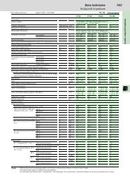
Electrical Data<br />
<strong>FMX</strong> switchgear system 12 kV 17.5 kV 24 kV<br />
Rated Voltage kV 12 17.5 24<br />
Lightning Impulse withstand voltage kV 75 95 125<br />
Power frequency withstand voltage kV 28 38 50<br />
Rated frequency Hz 50 50 50<br />
Internal arc class AFL 25 kA - 1 s AFL 25 kA - 1 s AFL 25 kA - 1 s<br />
Loss of service continuity category LSC2B LSC2B LSC2B<br />
Partition class PM PM PM<br />
Earthing circuit kA - s 25 - 3 25 - 3 25 - 3<br />
Compartment circuit-breaker/cable Interlock-controlled Interlock-controlled Interlock-controlled<br />
Compartment busbar Tool-based / Tool-based / Tool-based /<br />
non-accessible non-accessible non-accessible<br />
Degree of protection HV compartments (optional) IP4X IP4X IP4X<br />
Degree of protection LV compartment IP3XD IP3XD IP3XD<br />
Temperature classification Minus 5 °C indoor Minus 5 °C indoor Minus 5 °C indoor<br />
Busbar system<br />
Rated normal current A 2000 2000 2000<br />
Rated short-time withstand current kA - s 25 - 3 25 - 3 25 - 3<br />
Rated peak withstand current kA 63 63 63<br />
Circuit-breaker - incoming feeder and sectionalizer<br />
Rated normal current A 1250 - 1600 - 2000 1250 - 1600 - 2000 1250 - 1600 - 2000<br />
Rated short-circuit breaking current kA 25 25 25<br />
Rated short-circuit making current kA 63 63 63<br />
Rated short-time withstand current kA - s 25 - 3 25 - 3 25 - 3<br />
Circuit-breaker - outgoing feeder<br />
Rated normal current A 630 - 800 630 - 800 630 - 800<br />
Rated short-circuit breaking current kA 25 25 25<br />
Rated short-circuit making current kA 63 63 63<br />
Rated short-time withstand current kA - s 25 - 3 25 - 3 25 - 3<br />
Class E2, C2 E2, C2 E2, C2<br />
Operating cycles at short-circuit current 100 100 100<br />
Single capacitor bank switching A 400 400 400<br />
Mechanism<br />
Rated operating sequence A O - 0.3 s - CO - 15 s - CO O - 0.3 s - CO - 15 s - CO O - 0.3 s - CO - 15 s - CO<br />
Class M2 M2 M2<br />
Opening time ms 35 35 35<br />
DC component % 35 35 35<br />
Closing time ms 70 70 70<br />
Number of operations actuator 30,000 30,000 30,000<br />
Number of operations interrupter 30,000 30,000 30,000<br />
Auxiliary voltage V 48, 60,110, 220 VDC<br />
110/230 VAC<br />
48, 60,110, 220 VDC<br />
110/230 VAC<br />
48, 60,110, 220 VDC<br />
110/230 VAC<br />
Mechanism change-over switch<br />
Opening time s 24 24 24<br />
Closing time s 24 24 24<br />
Number of operations change-over switch 1,000 1,000 1,000<br />
Class M0 M0 M0<br />
Standards<br />
<strong>FMX</strong> complies with the following international standards<br />
IEC 62271-1 Common specifications<br />
IEC 62271-100 Circuit-breakers (E2, M2, C2)<br />
IEC 62271-102 Disconnectors and earthing switches (E2, M0)<br />
IEC 62271-200 Metal enclosed switchgear and controlgear<br />
IEC 60044-1 Current transformers<br />
IEC 60044-2 Voltage transformers<br />
IEC 60529 Degrees of protection (IP Code)<br />
IEC 61850 Communication networks and systems in substations<br />
IEC 61243-5 Live working - Voltage detectors - Part 5: Voltage detecting systems<br />
18
The power of fusion.<br />
1874 1886 1893 1899 1906 1908 1911 1962 1963 1983 1990 1998 1999<br />
There’s a certain energy at Eaton. It’s the power of uniting some<br />
of the world’s most respected names to build a brand you can<br />
trust to meet every power management need. The energy created<br />
supports our commitment to powering business worldwide.<br />
From power distribution to power quality and control, Eaton allows<br />
you to proactively manage your complete power system by<br />
providing electrical solutions that make your applications safer,<br />
more reliable, and highly efficient. Visit www.eaton.com/electrical.<br />
All of the above are trademarks of Eaton Corporation or its affiliates. Eaton has a license<br />
to use the Westinghouse brand name in Asia Pacific. ©2009 Eaton Corporation.
Eaton's Electrical Sector is a<br />
global leader in power<br />
distribution, power quality,<br />
control and automation, and<br />
monitoring products. When<br />
combined with Eaton's full-scale<br />
engineering services, these<br />
products provide customerdriven<br />
PowerChain ® solutions<br />
to serve the power system<br />
needs of the data center,<br />
industrial, institutional, public<br />
sector, utility, commercial,<br />
residential, IT, mission critical,<br />
alternative energy and OEM<br />
markets worldwide.<br />
PowerChain Management<br />
solutions help enterprises<br />
achieve sustainable and<br />
competitive advantages through<br />
proactive management of the<br />
power system as a strategic,<br />
integrated asset throughout its<br />
life cycle, resulting in enhanced<br />
safety, greater reliability and<br />
energy efficiency.<br />
For more information, visit<br />
www.eaton.com/electrical.<br />
PowerChain ® solutions help<br />
enterprises achieve sustainable<br />
and competitive advantages<br />
through proactive management<br />
of the power system as a<br />
strategic, integrated asset<br />
throughout its life cycle,<br />
resulting in enhanced safety,<br />
greater reliability and energy<br />
efficiency.<br />
For more information, visit<br />
www.eaton.com/electrical.<br />
Eaton medium voltage products in the energy chain<br />
Power plants<br />
Main stations<br />
3 4 5 6<br />
Infrastructure<br />
2 3 4 5 6<br />
Green energy<br />
1 2 3<br />
Commercial buildings<br />
1 2 3 4 6<br />
Offshore and<br />
marine 4 6<br />
Heavy industry<br />
4 5 6<br />
Distribution<br />
substations<br />
3 4 5 6<br />
Shops and<br />
offices<br />
Transformer<br />
stations 1 2<br />
Residential<br />
applications<br />
Power generation<br />
Process<br />
industry<br />
2 3 4 5 6<br />
Industry<br />
1 2 3 4 5 6<br />
Green energy<br />
1 2<br />
Solutions and<br />
Services<br />
1 Magnefix<br />
2 Xiria<br />
3 SVS<br />
4 <strong>FMX</strong><br />
5 MMS<br />
6 Unitole UX<br />
Eaton Electric B.V.<br />
P.O. Box 23<br />
7550 AA Hengelo<br />
The Netherlands<br />
Tel.: +31 (0)74 - 246 40 10<br />
Fax: +31 (0)74 - 246 40 25<br />
holec-info@eaton.com<br />
www.eatonelectric.com<br />
© 2010 Eaton Electric B.V.<br />
All rights reserved.<br />
Form No. <strong>6054012BR01</strong>/SG<br />
August 2010