Transistor Inverter - esco Antriebstechnik
Transistor Inverter - esco Antriebstechnik
Transistor Inverter - esco Antriebstechnik

You also want an ePaper? Increase the reach of your titles
YUMPU automatically turns print PDFs into web optimized ePapers that Google loves.
11<br />
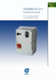
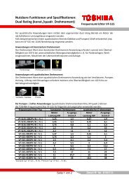
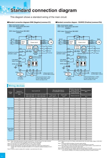
Standard connection diagram<br />
This diagram shows a standard wiring of the main circuit.<br />
■Standard connection diagraam-SINK (Negative) (common:CC) ■Standard connection diagram - SOURCE (Positive) (common:P24)<br />
Main circuit power supply<br />
240V class:three-phase 200-240V<br />
-50/60Hz<br />
400V class:three-phase 380-480V<br />
-50/60Hz<br />
Voltage<br />
class<br />
Three-phase<br />
200V class<br />
Three-phase<br />
400V class<br />
Note 9)<br />
MCCB R/L1<br />
S/L2<br />
T/L3<br />
Protectivve function<br />
activation output<br />
FLC<br />
FLB<br />
FLA<br />
RY<br />
Low-speed<br />
signal output RC<br />
24Vdc input PLC<br />
Noise<br />
filter<br />
Capacity of<br />
applicable motor<br />
(kW)<br />
PLC<br />
PA/+ PC/−<br />
Control<br />
circuit<br />
VF-FS1<br />
SW4<br />
SOURCE<br />
Power circuit<br />
200V class:200V<br />
400V class:380V<br />
F<br />
R<br />
RES<br />
Operation CC<br />
panel<br />
P24<br />
Connector for common<br />
serial communications<br />
Input current (A)<br />
U/T1<br />
V/T2<br />
W/T3<br />
200V class:240V<br />
400V class:480V<br />
Motor<br />
I M<br />
Forward<br />
Reverse<br />
Reset<br />
Common<br />
SINK I I<br />
FM CC VIA VIB PP<br />
Meter +<br />
Frequency<br />
meter<br />
(ammeter)<br />
−<br />
7.5V-1mA<br />
(or 4-20mA)<br />
+<br />
Voltage signal:0-10V<br />
−<br />
(Current signal:4-20mA)<br />
External potentiometer(1-10kΩ)<br />
(or input voltage signal across<br />
VIB-CC terminals:0-10V)<br />
Wiring devices<br />
0.4<br />
0.75<br />
1.5<br />
2.2<br />
3.7<br />
5.5<br />
7.5<br />
11<br />
15<br />
18.5<br />
22<br />
30<br />
0.4<br />
0.75<br />
1.5<br />
2.2<br />
3.7<br />
5.5<br />
7.5<br />
11<br />
15<br />
18.5<br />
22<br />
30<br />
1.9<br />
3.3<br />
6.1<br />
8.7<br />
15.7<br />
20.8<br />
27.9<br />
42.1<br />
56.1<br />
67.3<br />
80.4<br />
113.3<br />
1.0<br />
1.7<br />
3.2<br />
4.6<br />
8.1<br />
10.9<br />
14.7<br />
21.1<br />
28.5<br />
34.8<br />
41.6<br />
56.7<br />
Note 1: Sizes of the wires connected to the input terminals R/L1, S/L2 and T/L3 and the output terminals<br />
U/T1, V/T2 and W/T3 when the length of each wire does not exceed 30m.<br />
Note 2: For the control circuit, use shielded wires 0.75 mm 2 or more in diameter.<br />
Note 3: For grounding, use a cable with a size equal to or larger than the above.<br />
Note 4: The wire sizes specified in the above table apply to HIV wires (cupper wires shielded with an<br />
insulator with a maximum allowable temperature of 75°C) used at an ambient temperature of 40°C<br />
or less.<br />
Note 5: If there is a need to comply with UL standard , use correct size of UL wires.<br />
FM<br />
V<br />
VIA<br />
V<br />
1.6<br />
2.7<br />
5.1<br />
7.3<br />
13.0<br />
17.3<br />
23.3<br />
34.4<br />
45.5<br />
55.8<br />
66.4<br />
89.5<br />
0.8<br />
1.4<br />
2.5<br />
3.6<br />
6.4<br />
8.6<br />
11.7<br />
16.8<br />
22.8<br />
27.8<br />
33.1<br />
44.7<br />
Wire size (See Note 4)<br />
For IEC60364-5-523/54<br />
Power circuit<br />
(mm 2 ) Note 1)<br />
1.5<br />
1.5<br />
1.5<br />
1.5<br />
2.5<br />
4<br />
6<br />
10<br />
16<br />
25<br />
25<br />
50<br />
1.5<br />
1.5<br />
1.5<br />
1.5<br />
1.5<br />
1.5<br />
1.5<br />
4<br />
6<br />
6<br />
10<br />
16<br />
Main circuit power supply<br />
200V class: three-phase 200-240V<br />
-50/60Hz<br />
400V class: three-phase 380-480V<br />
-50/60Hz<br />
MCCB R/L1<br />
S/L2<br />
T/L3<br />
Protective function<br />
activation output<br />
Earth cable<br />
(mm 2 )<br />
2.5<br />
2.5<br />
2.5<br />
2.5<br />
2.5<br />
4<br />
6<br />
10<br />
16<br />
16<br />
16<br />
25<br />
2.5<br />
2.5<br />
2.5<br />
2.5<br />
2.5<br />
2.5<br />
2.5<br />
4<br />
6<br />
6<br />
10<br />
16<br />
FLC<br />
FLB<br />
FLA<br />
RY<br />
Low-speed<br />
signal output RC<br />
24Vdc input PLC<br />
Noise<br />
filter<br />
Molded case circuit<br />
breaker (MCCB)<br />
Earth leakage circuit<br />
breaker (ELCB)<br />
Control<br />
P24<br />
circuit<br />
F<br />
R<br />
Operation panel RES<br />
VF-FS1<br />
PLC<br />
Rated current (A)<br />
3<br />
5<br />
10<br />
15<br />
30<br />
40<br />
50<br />
75<br />
100<br />
100<br />
125<br />
175<br />
3<br />
3<br />
5<br />
10<br />
15<br />
20<br />
30<br />
40<br />
50<br />
60<br />
75<br />
100<br />
PA/+ PC/−<br />
SW4<br />
SOURCE<br />
SINK<br />
Power circuit<br />
Connector for<br />
common serial<br />
communications<br />
I I<br />
Magnetic contactor<br />
(MC)<br />
Operational current(A)<br />
AC-1<br />
25<br />
25<br />
25<br />
25<br />
25<br />
32<br />
40<br />
50<br />
80<br />
80<br />
100<br />
125<br />
25<br />
25<br />
25<br />
25<br />
25<br />
25<br />
32<br />
32<br />
40<br />
50<br />
80<br />
80<br />
U/T1<br />
V/T2<br />
W/T3<br />
Motor<br />
I M<br />
Forward<br />
Reverse<br />
Reset<br />
FM CC VIA VIB PP<br />
Meter +<br />
Frequency<br />
meter<br />
(ammeter)<br />
-<br />
+<br />
Voltage signal: 0-10V<br />
- (Current signal: 4-20mA)<br />
External potentiometer (1~10kΩ)<br />
7.5V-1mA<br />
(or input voltage signal across<br />
(or 4-20mA)<br />
VIB-CC terminals: 0-10V)<br />
Note 6: Selections for use of the Toshiba 4-pole standard motor with power supply voltage of 200V/400V-<br />
50Hz.<br />
Note 7: Choose the MCCB according to the power supply capacity.<br />
For comply with UL and CSA standard, use the fuse certified by UL and CSA.<br />
Note 8: When using on the motor side during commercial-power supply operation, choose the MC with<br />
class AC-3 rated current for the motor rated current.<br />
Note 9: Attach surge killers to the magnetic contactor and exciting coil of the relay.<br />
Note 10: In the case the magnetic contactor (MC) with 2a-type auxiliary contacts is used for the control<br />
circuit, raise the reliability of the contact by using 2a-type contacts in parallel connection.<br />
FM<br />
V<br />
VIA<br />
V<br />
Main circuit terminal<br />
Terminal symbol Terminal function<br />
R/L1, S/L2, T/L3<br />
U/T1, V/T2, W/T3<br />
PA/+, PC/-<br />
Control circuit terminal<br />
Terminal symbol Input/output<br />
F<br />
R<br />
RES<br />
PLC<br />
CC<br />
PP<br />
VIA<br />
VIB<br />
FM<br />
P24<br />
FLA<br />
FLB<br />
FLC<br />
RY<br />
RC<br />
Input<br />
Input<br />
Input<br />
Input<br />
(common)<br />
Common to<br />
Input/output<br />
Output<br />
Input<br />
Input<br />
Output<br />
Output<br />
Output<br />
Output<br />
Grounding terminal for connecting inverter.<br />
There are 3 terminals in total. 2 terminals in the terminal board, 1 terminal in the cooling fin.<br />
200V class: three-phase 200 to 240V-50/60Hz<br />
400V class: three-phase 380 to 480V-50/60Hz<br />
Connect to a (three-phase induction) motor.<br />
PA/+ terminal: Positive potential terminal for the internal DC main circuit<br />
PC/- terminal: Negative potential terminal for the internal DC main circuit<br />
DC power can be supplied through the PA/+ and PC/- terminals.<br />
Multifunction<br />
programmable<br />
contact input<br />
Function<br />
Shorting across F-CC causes forward rotation; open causes slow-down and stop.<br />
(When ST is always ON)<br />
Shorting across R-CC causes reverse rotation; open causes slow-down and stop.<br />
(When ST is always ON)<br />
This inverter protective function is disabled if RES are CC is connected.<br />
Shorting RES and CC has no effect when the inverter is in a normal condition.<br />
External 24Vdc power input<br />
When the source logic is used, a common terminal is connected.<br />
Control circuit's equipotential terminal (2 terminals)<br />
Analog power supply output<br />
Multifunction programmable analog input.<br />
Factory default setting: 0~10Vdc/0~60Hz (0~50Hz) frequency input.<br />
The function can be changed to 4~20mAdc (0~20mA) current input by flipping the VIA<br />
(SW3) dip switch to the I position.<br />
By changing parameter setting, this terminal can also be used as a multifunction<br />
programmable contact input terminal. When using the sink logic, be sure to insert a resistor<br />
between P24-VIA (4.7 kΩ-1/2 W). Also move the VIA (SW3) dip switch to the V position.<br />
Multifunction programmable analog input.<br />
Standard default setting: 0~10Vdc/0~60Hz (0~50Hz) frequency input.<br />
PTC thermal input<br />
Multifunction programmable analog output. Standard default setting: output frequency.<br />
The function can be changed to 0-20mAdc (4-20mA) current output by flipping the FM<br />
(SW2) slide switch to the I position.<br />
24Vdc power output<br />
Multifunction programmable relay contact output.<br />
Detects the operation of the inverter’s protection function.<br />
Contact across FLA-FLC is closed and FLB-FLC is opened during protection function<br />
operation.<br />
Multifunction programmable relay contact output.<br />
Standard default settings detect and output low-speed signal output frequencies.<br />
Multifunction output terminals to which two different functions can be assigned.<br />
Electrical specifications<br />
No voltage<br />
contact input<br />
24Vdc-5mA or less<br />
*Sink/Source/PLC<br />
selectable using SW4<br />
24VDC<br />
(Insulation resistance: DC50V)<br />
—<br />
10Vdc<br />
(permissible load current: 10mA)<br />
10Vdc<br />
(internal impedance: 30kΩ)<br />
4-20mA<br />
(internal impedance: 250Ω)<br />
10Vdc<br />
(internal impedance: 30kΩ)<br />
1mAdc full-scale ammeter or 7.5Vdc<br />
(10Vdc)1mA full-scale voltmeter<br />
0-20mA (4-20mA) DC ammeter<br />
Permissible load resistance:<br />
750Ω or less<br />
24Vdc-50mA<br />
250Vac-1A(cosφ=1): at resistance load<br />
30Vdc-0.5A, 250Vac-0.5A(cosφ=0.4)<br />
250Vac-1A(cosφ=1): at resistance load<br />
30Vdc-0.5A, 250Vac-0.5A(cosφ=0.4)<br />
12