Wire Rope Sling Load Charts
Wire Rope Sling Load Charts
Wire Rope Sling Load Charts

You also want an ePaper? Increase the reach of your titles
YUMPU automatically turns print PDFs into web optimized ePapers that Google loves.
1819 2nd Avenue N.<br />
P.O. Box 30637<br />
Billings, MT 59107-0637<br />
(406) 248-1151<br />
(800) 488-3754<br />
8989 Roller Coaster Road<br />
Missoula, MT 59808<br />
(406) 543-2982<br />
(800) 775-2794<br />
www.nwisupply.com<br />
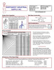
Choker Hitch Capacities<br />
When the pull on a choker hitch results in an angle of less than<br />
120 o , the work load limit must be adjusted. Determine the angle of<br />
choke and multiply the choker hitch work load limit<br />
by the loss factor to get the reduced work load.<br />
<br />
<br />
<br />
<br />
<br />
<br />
<br />
<br />
<br />
!<br />
<br />
<br />
<br />
<br />
<br />
<strong>Wire</strong> <strong>Rope</strong> Construction<br />
Core<br />
One <strong>Rope</strong> Lay<br />
(D/d) Considerations<br />
<strong>Wire</strong><br />
Center <strong>Wire</strong><br />
Strand<br />
<strong>Wire</strong> <strong>Rope</strong><br />
When wire rope is bent around the load diameter,<br />
the rope strength is decreased. The D/d ratio is the<br />
diameter of the object around which the rope is bent<br />
(D), divided by the diameter (d) of the rope.<br />
<strong>Sling</strong> <strong>Load</strong> Chart<br />
<br />
<br />
•<br />
<br />
<br />
<br />
<br />
<br />
<br />
<br />
<br />
<br />
<br />
<br />
<br />
<br />
<br />
<br />
<br />
<br />
<br />
<br />
<br />
! <br />
!" #<br />
$ %&<br />
'"<br />
#<br />
<br />
( <br />
$ %&<br />
<br />
<br />
<br />
<br />
<br />
<br />
<br />
<br />
<br />
<br />
<br />
<br />
<br />
<br />
<br />
<br />
<br />
<br />
<br />
<br />
<br />
<br />
<br />
<br />
<br />
<br />
<br />
<br />
<br />
<br />
<br />
<br />
<br />
<br />
<br />
<br />
<br />
<br />
<br />
This chart illustrates how the stress in a sling<br />
increases as the angle increases (all angles are<br />
measured from the vertical).<br />
When one sling leg lifts 1,000 lbs. at 0 o , the sling<br />
stress is also 1,000 lbs. If the sling angle increases<br />
to 45 o , the stress actually exerted on the sling<br />
would be 1,414 lbs., an increase of 41.4%.<br />
Should the sling angle be increased to 60 o , the<br />
stress would be 2,000 lbs., or a 100% increase. At<br />
an 85 o angle (highly unlikely), sling stress increases<br />
1,047%. With a load of 1,000 lbs., the sling stress<br />
would be 11,473 lbs.<br />
How to Select a <strong>Sling</strong> for Use at Any Angle<br />
When calculating for selection of the proper sling,<br />
select the vertical angle in the chart at left. Read the<br />
“increase in stress” as a percentage factor. Multiply<br />
the actual load weight by this percentage, then add<br />
the answer to the actual load to be lifted. This gives<br />
the rated capacity to look for in selecting the proper<br />
size of sling.<br />
Efficiencies of <strong>Wire</strong> <strong>Rope</strong> <strong>Sling</strong>s<br />
These figures represent the efficiency of the attachment. The approximate percentage of effective rope strength<br />
available with each type of fitting depends upon the diameter, construction and grade of rope.<br />
<strong>Wire</strong> rope sockets - Spelter attachment 100% Thimble Splice: 3/8” to 5/8” diameter 90-95%<br />
“Swage sleeve” thimble attachment 100% 3/4” to 1 1/8” diameter 85-90%<br />
“Swage-sleeve” loop attachment 100% 1 1/4” to 1 1/2” diameter 80-85%<br />
Wedge sockets (depending on design) 80-90% 1 5/8” to 2” diameter 75-80%<br />
Clips (number of clips varies w/ rope size) 80% 2 1/8” and up 70-75%<br />
Loop Splice: The efficiency of a loop splice without a thimble is somewhat less than given above for a thimble splice.
Nylon Web <strong>Sling</strong>s<br />
Eye & Eye (EE) & Endless (EN) style slings - 1 & 2 Ply <strong>Sling</strong>s<br />
Rated Capacities in Lbs. based on 9800 lbs webbing. Design Factor = 5:1 when new.<br />
<br />
<br />
<br />
!<br />
<br />
<br />
<br />
!<br />
<br />
<br />
<br />
<br />
<br />
<br />
<br />
<br />
<br />
<br />
Polyester Roundslings<br />
Rated Capacities in Lbs. Design Factor = 5:1 when new.<br />
<br />
<br />
<br />
<br />
<br />
<br />
<br />
<br />
<br />
<br />
<br />
<strong>Sling</strong>max ® HPF Twin-Path <strong>Sling</strong>s ®<br />
Rated Capacities in Lbs. Design Factor = 5:1 when new.<br />
$!% $ % <br />
<br />
<br />
<br />
<br />
<br />
<br />
<br />
! !<br />
" "<br />
# #<br />
<br />
<br />
<br />
" <br />
<br />
<br />
" <br />
<br />
<br />
<br />
Removal from Service Criteria<br />
for Synthetic <strong>Sling</strong>s<br />
All slings must be inspected daily or before each shift<br />
in normal service conditions. If conditons are severe<br />
or you’re unsure if the sling has been inspected, YOU<br />
NEED TO INSPECT THE SLING BEFORE USING.<br />
<strong>Sling</strong>s shall be removed from service if any of the<br />
following conditions are present :<br />
All <strong>Sling</strong>s<br />
• Missing or illegible tag<br />
• Holes, tears, cuts, snags, punctures or knots<br />
• Acid or alkali burns<br />
• Melting, charring or weld splatter<br />
• Distortion, pitting, corrosion or other fitting damage<br />
• Any condition that causes doubt as to the strength<br />
of the sling.<br />
• Damaged slings must not be used for ANY purpose!<br />
Roundslings And Twin-path ® <strong>Sling</strong>s<br />
• Damage to the cover that exposes yarn<br />
• Broken, cut or damaged core yarns<br />
• Damage to the cover may indicate a loss of core<br />
yarn strength.<br />
For <strong>Sling</strong>s Equipped With:<br />
• Check-Fast ® : The EWI does not extend past the<br />
sling tag area.<br />
• Tattle Tails: One or both of the tails does not extend<br />
past the sling tag area.<br />
• Fiber Optics: Light is not transmitted.<br />
Web <strong>Sling</strong>s<br />
• Excessive abrasion<br />
• Crushed webbing<br />
• Ultraviolet light damage<br />
• Broken or worn stitching in load bearing splices<br />
• Red core yarn if furnished. If there is damage and<br />
the red yarns are not visible, DO NOT USE THE<br />
SLING! Remember, ANY DOUBT, DON’T!<br />
Wear Protection for <strong>Sling</strong>s<br />
All slings must be protected from damage by<br />
materials of sufficient strength, thickness and<br />
construction.<br />
The edge of a load need not be “razor” sharp to<br />
cut slings.<br />
If the load moves across the sling or the sling<br />
across the load, the sling may become damaged.<br />
There is no such thing as “Cut Proof” wear protection.<br />
Cut resistant wear protection does exist.<br />
There is a BIG difference between abrasion and<br />
cutting damage and the appropriate wear protection<br />
to use for each.<br />
Gloves and cardboard are not wear protection<br />
devises.<br />
Contact us for wear protection that is engineered<br />
to withstand tension and compression.<br />
Engineered Wear Protection<br />
Cornermax ® Sleeves<br />
Cornermax ® Pad<br />
Magnetic Corner Protectors<br />
Meshguard ®
Alloy Chain <strong>Sling</strong>s Grade 80/Grade 100<br />
Rated Capacities in Lbs. Design Factor = 4:1 when new.<br />
<br />
<br />
<br />
<br />
<br />
<br />
<br />
<br />
<br />
<br />
<br />
<br />
<br />
<br />
<br />
<br />
<br />
<br />
<strong>Sling</strong> Tension and Weight Distribution<br />
Center of Gravity Centered<br />
Offset Center of Gravity<br />
Proportional<br />
Share of<br />
the <strong>Load</strong><br />
x<br />
<strong>Load</strong> Factor<br />
<strong>Sling</strong> Tension<br />
Proportional<br />
Share of<br />
the <strong>Load</strong><br />
x<br />
<strong>Load</strong> Factor<br />
<strong>Sling</strong> Tension<br />
3<br />
12<br />
6 ft. Leg<br />
=<br />
.25 Distance<br />
.75 Share of <strong>Load</strong><br />
.75 x 55,000 = 41,250<br />
x<br />
L1<br />
H = 6<br />
= 1.2<br />
5<br />
10.5 ft. Leg<br />
9<br />
12<br />
49,500 lbs.<br />
=<br />
.75 Distance<br />
.25 Share of <strong>Load</strong><br />
.25 x 55,000 = 13,750<br />
L2<br />
H = 10.5 x<br />
= 2.1<br />
5<br />
28,875 lbs.<br />
Rigging Hardware Capacities<br />
Rated Capacities in Lbs. Design Factor = 5:1 when new.<br />
,+ - .<br />
) <br />
<br />
+ <br />
*+ <br />
/ 0 +. / <br />
/. /. #1 !1 <br />
! "! #! " "$<br />
%& ' ' !! "! '$<br />
' "" '' ! '" (& '! '&$<br />
!& "! %! ''! !' !" "$<br />
% #! !' % (' '" ! $<br />
(& % # (' " %& & "$<br />
( '! ! %% %## '%$<br />
& # % '%$<br />
' %" !' ' "% ! ($<br />
' % ' ' (' '! &$<br />
Calculating <strong>Load</strong> Weights<br />
<br />
<br />
<br />
<br />
<br />
<br />
<br />
<br />
<br />
<br />
<br />
<br />
!"<br />
<br />
#$ <br />
%!&'( )<br />
%!&' ( <br />
*<br />
<br />
*<br />
<br />
+ <br />
+<br />
<br />
,<br />
)<br />
,-<br />
<br />
,-<br />
<br />
,- <br />
.<br />
<br />
/ <br />
0<br />
/<br />
<br />
1<br />
<br />
<br />
<br />
203 4)<br />
23 4<br />
23 )<br />
3 <br />
Read the Label!<br />
ASME standards<br />
require all slings to be<br />
marked with manufacturer,<br />
stock number and rated loads for the<br />
types of hitches used and the angle upon which<br />
it is based, as well as other information pertinent<br />
to sling type.<br />
Coefficients of Friction<br />
<br />
<br />
<br />
<br />
<br />
<br />
<br />
<br />
<br />
<br />
<br />
<br />
<br />
"<br />
<br />
<br />
!
1819 2nd Avenue N.<br />
P.O. Box 30637<br />
Billings, MT 59107-0637<br />
(406) 248-1151<br />
(800) 488-3754<br />
8989 Roller Coaster Road<br />
Missoula, MT 59808<br />
(406) 543-2982<br />
(800) 775-2794<br />
www.nwisupply.com<br />
<strong>Wire</strong><br />
<strong>Rope</strong><br />
<strong>Sling</strong>s<br />
)"<br />
&*<br />
+$,<br />
-$''<br />
.#-/<br />
+0"",<br />
<br />
1<br />
-/<br />
<br />
<br />
<br />
<br />
<br />
<br />
<br />
<br />
<br />
<br />
<br />
<br />
<br />
<br />
<br />
<br />
<br />
<br />
<br />
!""#$#%$&'(<br />
<br />
2<br />
.#<br />
1<br />
"<br />
Two Leg<br />
Bridle<br />
<strong>Sling</strong>s<br />
<br />
<br />
!"#<br />
<br />
<br />
<br />
$%<br />
&'<br />
(<br />
)'<br />
*'<br />
<br />
<br />
<br />
<br />
<br />
<br />
<br />
<br />
<br />
<br />
<br />
<br />
<br />
<br />
<br />
<br />
<br />
<br />
Three Leg<br />
Bridle<br />
<strong>Sling</strong>s<br />
<br />
<br />
!"#<br />
<br />
<br />
<br />
$%<br />
&'<br />
(<br />
)'<br />
*'<br />
<br />
<br />
<br />
<br />
<br />
<br />
<br />
<br />
<br />
<br />
<br />
<br />
<br />
<br />
<br />
<br />
Four Leg<br />
Bridle<br />
<strong>Sling</strong>s<br />
<br />
<br />
!"<br />
<br />
<br />
<br />
t EIPS IWRC - Extra Improved Plow Steel with Independent <strong>Wire</strong> <strong>Rope</strong> Core<br />
#$<br />
%&<br />
'<br />
(&<br />
)&<br />
<br />
* <br />
<br />
<br />
<br />
<br />
<br />
<br />
<br />
<br />
<br />
<br />
<br />
<br />
Alloy Links<br />
<br />
<br />
<br />
<br />
<br />
<br />
<strong>Sling</strong> Types<br />
Loop Thimble Thimble<br />
& Hook<br />
<strong>Sling</strong> Uses<br />
Choker Vertical Vertical<br />
Basket