Low-Power Circuit Techniques for Low-Voltage Pipelined ADCs ...
Low-Power Circuit Techniques for Low-Voltage Pipelined ADCs ...
Low-Power Circuit Techniques for Low-Voltage Pipelined ADCs ...

You also want an ePaper? Increase the reach of your titles
YUMPU automatically turns print PDFs into web optimized ePapers that Google loves.
IEICE TRANS. FUNDAMENTALS, VOL.E91–A, NO.2 FEBRUARY 2008<br />
461<br />
PAPER<br />
Special Section on Analog <strong>Circuit</strong> <strong>Techniques</strong> and Related Topics<br />
<strong>Low</strong>-<strong>Power</strong> <strong>Circuit</strong> <strong>Techniques</strong> <strong>for</strong> <strong>Low</strong>-<strong>Voltage</strong> <strong>Pipelined</strong> <strong>ADCs</strong><br />
Based on Switched-Opamp Architecture<br />
Hsin-Hung OU †a) , Student Member, Soon-Jyh CHANG † , Nonmember, and Bin-Da LIU † , Member<br />
SUMMARY This paper proposes useful circuit structures <strong>for</strong> achieving<br />
a low-voltage/low-power pipelined ADC based on switched-opamp architecture.<br />
First, a novel unity-feedback-factor sample-and-hold which manipulates<br />
the features of switched-opamp technique is presented. Second,<br />
opamp-sharing is merged into switched-opamp structure with a proposed<br />
dual-output opamp configuration. A 0.8-V, 9-bit, 10-Msample/s pipelined<br />
ADC is designed to verify the proposed circuit. Simulation results using<br />
a 0.18-μm CMOS 1P6M process demonstrate the figure-of-merit of this<br />
pipelined ADC is only 0.71 pJ/step.<br />
key words: low-voltage, switched-opamp, sample-and-hold, opampsharing,<br />
pipelined ADC<br />
1. Introduction<br />
Serving as a crucial component in many communicationrelated<br />
products, analog-to-digital converters (<strong>ADCs</strong>) with<br />
high per<strong>for</strong>mance while dissipating low power are highly<br />
preferred. <strong>Pipelined</strong> ADC proves to be a popular architecture<br />
since it employs concurrent operation to achieve high<br />
throughput in a power-efficient manner. However, as process<br />
technology scales, the design of pipelined ADC becomes<br />
much more complicated when low-voltage is also a<br />
significant concern. <strong>Low</strong>er supply voltage inherently translates<br />
into lower power in digital domain while this is not the<br />
case considering analog circuit [1], [2]. In order to maintain<br />
the required dynamic range and speed per<strong>for</strong>mance with<br />
reduced voltage supply, extra power is needed to suppress<br />
the noise floor as well as boosting the opamp bandwidth.<br />
As a result, <strong>for</strong> a given signal-to-noise ratio (SNR) specification,<br />
the total power consumption will inversely increase<br />
with reduced supply. Insufficient switch overdrive voltage is<br />
another critical problem <strong>for</strong> low-voltage circuit which may<br />
lead to higher distortion and longer settling. Limited opamp<br />
structure choices which often fail to provide enough gain<br />
and bandwidth even deteriorate the situation.<br />
Many approaches have been proposed to deal with<br />
insufficient switch conduction at low voltage [2]–[4].<br />
Switched-opamp (SO) architecture removes the critical<br />
switch and replaces it with a switchable opamp [3]. It is<br />
fully compatible with deep-submicron technology and allows<br />
<strong>for</strong> extensive applications with low supply voltage such<br />
as switched-capacitor (SC) filters [5], [6], sigma-delta modulator<br />
[7], and pipelined <strong>ADCs</strong> [8]–[13].<br />
Manuscript received June 21, 2007.<br />
Manuscript revised September 10, 2007.<br />
† The authors are with the Department of Electrical Engineering,<br />
National Cheng Kung University, Tainan, Taiwan.<br />
a) E-mail: petero@spic.ee.ncku.edu.tw<br />
DOI: 10.1093/ietfec/e91–a.2.461<br />
For a switched-opamp based pipelined ADC, since<br />
lower supply voltage does not promise lower power, the<br />
power minimization issue can be tackled from two aspects<br />
by examining the power distribution phenomenon. In the<br />
architectural level, sample-and-hold (S/H) is the dominant<br />
power contributor since it processes the full resolution and<br />
bandwidth of an ADC [14]. In the circuit level, opamps generally<br />
consume more than 80% of an overall ADC power<br />
and there<strong>for</strong>e opamp-sharing are widely used in pipelined<br />
<strong>ADCs</strong> [15]–[18]. This work proposes power saving design<br />
techniques <strong>for</strong> switched-opamp based <strong>ADCs</strong> following<br />
these two guidelines. A novel S/H architecture is introduced<br />
to relax the power and noise contribution of traditional SObased<br />
S/H [9], [13]. Furthermore, a power-efficient ADC<br />
architecture by incorporating the opamp-sharing technique<br />
into switched-opamp configuration is presented [10]. A 0.8-<br />
V 9-bit 10-MS/s ADC is designed to demonstrate the proposed<br />
ideas.<br />
This paper is organized as follows: Sect. 2 presents<br />
the architecture of the proposed ADC. A novel S/H aswell<br />
as the SO-based opamp-sharing architecture which altogether<br />
constitute the low-voltage/low-power pipelined ADC<br />
are described and clarified. <strong>Low</strong>-voltage building blocks<br />
such as opamp and comparator are discussed in Sect. 3.<br />
Simulation results of the developed ADC using 0.18-μm<br />
CMOS 1P6M device models are demonstrated and analyzed<br />
in Sect. 4.<br />
2. Design Issues of Proposed <strong>Pipelined</strong> ADC<br />
2.1 ADC Architecture<br />
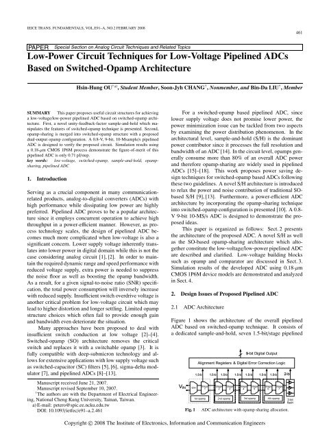
Figure 1 shows the architecture of the overall pipelined<br />
ADC based on switched-opamp technique. It consists of<br />
a dedicated sample-and-hold, seven 1.5-bit/stage pipelined<br />
Fig. 1<br />
ADC architecture with opamp-sharing allocation.<br />
Copyright c○ 2008 The Institute of Electronics, In<strong>for</strong>mation and Communication Engineers
462<br />
IEICE TRANS. FUNDAMENTALS, VOL.E91–A, NO.2 FEBRUARY 2008<br />
stages [19] and a final 2-bit flash ADC. A total of 16 bits<br />
are collected and processed by the digital error correction<br />
unit to remove the redundancy and retrieve the effective<br />
9-bit digital output. The front-end S/H is realized with a<br />
novel SO-based technique which allows itself to operate in<br />
unity-feedback configuration. In addition, opamp-sharing<br />
is applied along the pipeline stages. Total four opamps are<br />
used, in which S/H and first multiplying-digital-to-analogconverter<br />
(MDAC) share a common opamp and then the<br />
following six MDACs share the other three opamps. The<br />
opamp sharing allocation is illustrated as the dashed blocks<br />
in Fig. 1. The proposed S/H and opamp-sharing scheme are<br />
described in detail in the following sub-sections.<br />
2.2 Proposed SO-Based Sample-and-Hold<br />
Figure 2(a) shows the conventional flip-around architecture<br />
of a sample-and-hold circuit which is widely used in<br />
pipelined <strong>ADCs</strong> [2]. High speed per<strong>for</strong>mance and power<br />
efficiency can be achieved since its feedback factor is ideally<br />
equal to 1. Besides, there is no capacitor mismatch issue<br />
because one single capacitor plays both roles of sampling<br />
and feedback capacitor. However, such type of S/H<br />
cannot be used in low-voltage circuits owing to the critical<br />
switch connected to output nodes. If the S/H inFig.2(a)<br />
is operated with insufficient supply, S 1 and S 2 can only be<br />
poorly conducted during their respective on-phase because<br />
they are connected to either input or output nodes whose<br />
DC levels are set around V DD /2. There<strong>for</strong>e, flip-around S/H<br />
cannot be directly applied in low-voltage application. Several<br />
published work concerning low-voltage sampling circuits<br />
have been proposed [8], [9], [20]. Figure 2(b) depicts a<br />
common implementation of charge-redistribution type S/H<br />
which is adaptive to SO structure [9], [13]. During φ 1 ,the<br />
opamp is turned off and C S samples the input while C F is<br />
reset. During φ 2 , the opamp is activated and the differen-<br />
tial input charge is transferred from C S to C F to produce the<br />
corresponding V OUT . In this architecture, two bootstrapped<br />
switches [2] are used to interface the input signal <strong>for</strong> high<br />
linearity. All other switches are connected to either V DD<br />
or ground and hence no critical switches exist. A major<br />
drawback of this SO-based S/H is the reduced feedback factor<br />
compared to the traditional flip-around architecture. A<br />
reduced feedback factor β directly degrades the speed and<br />
noise per<strong>for</strong>mance since the closed-loop bandwidth ω u and<br />
output-referred noise v 2 o can be approximated by [14]<br />
ω u = β g m<br />
(1)<br />
C L<br />
v 2 o = kT<br />
(2)<br />
βC F<br />
where g m and C L represent the opamp’s input transconductance<br />
and output loading respectively, and kT is the<br />
thermal energy.<br />
We propose a novel SO-based sample-and-hold to<br />
solve this issue. The concept is based on the features of<br />
the switched-opamp architecture in two aspects: (a) the bottom<br />
plate of feedback capacitor is <strong>for</strong>ced to permanently<br />
connect to the output nodes of opamp. (b) The opamp is<br />
turned-off in one of the two non-overlapped phases, during<br />
which the output stage can be pulled to V DD or ground using<br />
additional switch. Thus the sampling behavior can be<br />
realized by directly attaching the sampling capacitors onto<br />
the output nodes of the opamp rather than connecting them<br />
to ground using additional switches. The proposed fullydifferential<br />
S/H architecture is shown in Fig. 3. C S 1 and C S 2<br />
sample the input signal respect to V DD at φ 1 since the opamp<br />
is currently turned-off and the output nodes are pulled to<br />
V DD .Duringφ 2 , the input signal path is terminated by turning<br />
off the bootstrapped switches, while the top plates of<br />
C S 1 and C S 2 are connected to the opamp input terminals,<br />
resulting in unity feedback and V OUT = V IN . Such configuration<br />
exploits the features of switched-opamp architecture<br />
and turns the drawbacks into benefits. It has the following<br />
advantages: The settling speed is potentially doubled<br />
compared to the S/H in Fig. 2(b) since the feedback factor is<br />
now ideally equal to 1 rather than 1/2. The improvement in<br />
feedback factor also implies the output-referred noise of the<br />
S/H is reduced by half according to Eq. (2). In a pipelined<br />
ADC, S/H usually dominates the overall noise per<strong>for</strong>mance<br />
(a)<br />
(b)<br />
Fig. 2 Conventional S/H in SC and SO implementation. (a) Flip-around<br />
architecture [2], (b) SO based S/H [9], [13].<br />
Fig. 3<br />
Proposed switched-opamp based S/H with unity feedback factor.
OU et al.: LOW-POWER CIRCUIT TECHNIQUES FOR LOW-VOLTAGE PIPELINED ADCS BASED ON SWITCHED-OPAMP ARCHITECTURE<br />
463<br />
because it locates at the front-end while the following stages<br />
attenuate their resulting noise through the interstage gain accumulated<br />
along the pipeline [14]. Reduced noise also indicates<br />
smaller loading capacitance and hence higher speed<br />
and lower power consumption can be achieved. Furthermore,<br />
slew-rate requirements are also relaxed because the<br />
opamp has to charge only the output node but not the feedback<br />
capacitor.<br />
Charge injection and clock feedthrough errors in S/H<br />
circuits can be treated as DC offset by turning off the switch<br />
connected to ground with an advanced clock phase shown<br />
in Fig. 2. In the proposed scheme, advanced clock phase is<br />
not required because the bootstrapped switch always ensures<br />
a constant overdrive voltage. The channel charge stored<br />
in bootstrapped switch is independent of the input signal,<br />
and the resulting injection during turn-off can be viewed<br />
as DC offset which can be eliminated by fully-differential<br />
structure. The threshold voltage variation due to body effect<br />
which contributes to high-order distortion can be alleviated<br />
by properly minimizing the bootstrapped switch size as<br />
long as the settling requirement is satisfied. Simulation results<br />
demonstrate that the proposed S/H achieves more than<br />
10 bit linearity at 10 MS/s, consuming only 0.3 mW at 0.8 V<br />
supply.<br />
2.3 Merging of Opamp-Sharing and Switched Opamp<br />
<strong>Techniques</strong> [10]<br />
Opamp-sharing technique is based on the principle that<br />
opamps operate only in the residue amplification phase but<br />
idle in sampling phase. However, two architectural limitations<br />
prevent opamp-sharing technique from straight<strong>for</strong>ward<br />
application into switched-opamp configuration. First,<br />
opamp-sharing demands the opamp to be used in both<br />
clock phases <strong>for</strong> sharing while switched-opamp turns off the<br />
opamp in one of the two phases in order to mimic the behavior<br />
of a switch. Second, capacitors which are connected<br />
to the output nodes of the opamp in switched-opamp implementation<br />
are not detachable. There<strong>for</strong>e, the opamp shared<br />
by one pipelined stage cannot be directly reused by the other<br />
without circuit modification. We have proposed a solution to<br />
solve this problem [10]. By adding one more output stage to<br />
the conventional two-stage opamp, switched-opamp configuration<br />
can be merged with opamp-sharing technique. The<br />
input stage is kept active in both phases <strong>for</strong> opamp-sharing<br />
while the dual output stages switch on/off in turn. When<br />
output stage 1 is turned-off, it provides the high impedance<br />
required <strong>for</strong> SO structure. At this moment, output stage 2 is<br />
turned on and used <strong>for</strong> opamp-sharing together with the input<br />
stage. Output stages 1 and 2 exchange their roles in the<br />
opposite clock phase and always operate complementarily.<br />
In this pipelined ADC, two types of opamp-shared<br />
stages are used as shown in Fig. 1. The first is a dedicated<br />
S/H with its opamp shared with the first MDAC. The<br />
other is opamp-shared stages between adjacent MDACs.<br />
Figure 4 shows the detailed circuit illustrating the opampsharing<br />
architecture between S/H and MDAC1. The following<br />
MDACs reuse opamps in a similar manner. As shown<br />
in Fig. 4, bootstrapped switches are used to interface the<br />
system input <strong>for</strong> minimizing the distortion and reducing<br />
the switch resistance. The opamp composes of two output<br />
stages in order to be shared with the following MDAC. During<br />
φ 1 , the system input directly charges the sampling capacitors<br />
C SH1 and C SH2 respect to the output nodes of V O2 since<br />
V O2 is turned-off and can be pulled up to V DD . The opamp’s<br />
input stage V I as well as the first output stage V O1 is currently<br />
used by MDAC1 to produce the residue <strong>for</strong> MDAC2.<br />
Next, in φ 2 , the top plates of the sampling capacitors are<br />
connected to opamp’s inputs, and the sampled input now<br />
appears on V O2 <strong>for</strong> MDAC1 to sample. The right part of<br />
Fig. 4<br />
Opamp-sharing between S/H and MDAC1.
464<br />
IEICE TRANS. FUNDAMENTALS, VOL.E91–A, NO.2 FEBRUARY 2008<br />
Table 1 <strong>Power</strong> comparison <strong>for</strong> a 9-bit SO-based pipelined ADC w/ and<br />
w/o opamp-sharing.<br />
9-bit <strong>Pipelined</strong> ADC in SO structure<br />
# of <strong>Circuit</strong> Without Opamp-Sharing with<br />
blocks Opamp-Sharing Dual-Output Opamp<br />
Opamp 8 4<br />
I/P Stage 8 4<br />
O/P Stage 8 4<br />
CMFB Amp. 8 4<br />
Estimated <strong>Power</strong> 100% 75%<br />
the dashed line in Fig. 4 shows the SC network of MDAC1<br />
[8]. C S , C F ,andC R denote the sampling capacitor, feedback<br />
capacitor and reference capacitor respectively. Capacitor<br />
values are arranged as C S = 2C F = 2C R . C S is chosen<br />
as two times the value of C F in order to provide an interstage<br />
gain of two. Since <strong>for</strong> switched-opamp configuration,<br />
the capacitors connected to the opamp output are no longer<br />
switchable, the commonly used flip-around MDAC [2] cannot<br />
be applied and the maximum achievable feedback factor<br />
is only 1/4, which is only half of traditional circuit. Normally<br />
an opamp is difficult to optimize when it is shared<br />
between a S/H and a MDAC because the closed-loop bandwidth<br />
in two phases are unequal. The proposed S/H which<br />
has unity feedback factor even complicates this power and<br />
speed tradeoff compared to original SO-based S/H with β<br />
= 1/2. However, in the proposed design, the dual output<br />
stages of a shared-opamp can provide a degree of freedom<br />
to be independently optimized <strong>for</strong> S/H and MDAC to solve<br />
this issue.<br />
2.4 <strong>Power</strong> Analysis<br />
In the proposed SO-based opamp-sharing technique, an<br />
opamp with dual output stages is required. The addition<br />
of one more output stage seems to increase the power consumption.<br />
However since the dual output stages turns on/off<br />
alternatively in one of the two nonoverlapped clock phases,<br />
the proposed opamp consumes only equal power as a normal<br />
opamp operated at both phases. Furthermore, from<br />
a systematic perspective, the proposed dual-output opamp<br />
is shared between adjacent pipelined stages; there<strong>for</strong>e approximately<br />
half of the power is saved. Table 1 provides a<br />
detailed comparison <strong>for</strong> a switched-opamp based pipelined<br />
ADC with/without using the proposed opamp-sharing architecture.<br />
For a 1.5-b/stage, 9-bit pipelined ADC with a dedicated<br />
S/H, total 8 opamps are required without opamp sharing.<br />
The power of common-mode feedback (CMFB) amplifier<br />
is also taken into consideration since it is necessary<br />
to provide common-mode signal inversion <strong>for</strong> low-voltage<br />
opamp [8], [13]. The current consumptions of input stage,<br />
output stage, and CMFB amplifier are assumed to be 1:2:1,<br />
respectively. Bias circuit is neglected <strong>for</strong> simplicity. As<br />
shown in Table 1, 25% power is saved by using the proposed<br />
architecture. In combination with the proposed S/H,<br />
more power can be saved.<br />
3. <strong>Circuit</strong> Design<br />
3.1 Opamp Design<br />
A nonideal opamp deteriorates the overall pipelined ADC<br />
linearity in mainly two ways: (1) linear but finite opamp<br />
gain and (2) nonlinear gain due to limited output swing. The<br />
latter may contribute more error due to reduced available<br />
swing in low-voltage applications. In the proposed design,<br />
sufficient gain is required to suppress the opamp-induced<br />
nonlinearity as well as the memory effect due to opampsharing<br />
[17].<br />
Figure 5(a) shows the fully differential switched opamp<br />
with dual output stages adopted in this pipelined ADC<br />
[6]. As a<strong>for</strong>ementioned, the merging of switched-opamp<br />
and opamp-sharing demand an opamp with dual output<br />
stages. There<strong>for</strong>e a conventional Miller-compensated twostage<br />
structure with dual switchable common-source output<br />
stages is used. Only one of the two output stages is<br />
turned on in each clock phase while the input stage is kept<br />
active in both phases so as to minimize the wake-up time.<br />
With input common-mode set to ground, a folded input<br />
stage with PMOS input pair is employed. The output stages<br />
apply simple common-source structure <strong>for</strong> rail-to-rail output<br />
swing. Zero-nulling resistors are used <strong>for</strong> compensation<br />
rather than MOS in order to prevent distortion caused<br />
by great impedance variation at low voltage. The output<br />
stages as well as their corresponding RC compensation networks<br />
can be separately optimized to meet the speed/power<br />
constraint set by different pipelined stages. The dynamic<br />
SC CMFB circuit as shown in Fig. 5(b) is used to provide<br />
proper output common-mode level control. Two sets of SC<br />
branches are required <strong>for</strong> dual output stages in both phases.<br />
The amplifier A 1 is used to provide the correct polarity <strong>for</strong><br />
CMFB control signal, and the circuit is simply the same as<br />
the input stage of the main opamp.<br />
In this paper, a 0.8-V, 9-bit, 10-MS/s pipelined ADC<br />
was designed to verify the proposed low-voltage powersaving<br />
circuit techniques. The gain and bandwidth requirements<br />
of the opamps in S/H andfirstMDACareofsignificant<br />
concern. Normally <strong>for</strong> an N-bit ADC, an opamp<br />
gain of 2 N+1 is required to assure finite gain induced error<br />
within ±1/2 LSB. Considering the fundamental nonideal effects<br />
such as process, temperature and supply variations, the<br />
minimum gain should be increased accordingly. In addition,<br />
in low voltage design, opamp experiences severe gain drift<br />
due to limited output range. There<strong>for</strong>e an extra gain is further<br />
demanded. As <strong>for</strong> the bandwidth requirement, opamp<br />
must settle within ±1/2 LSB in half of the sampling period.<br />
The relationship between the unity gain frequency of opamp<br />
and the ADC resolution can be expressed as follows [14]:<br />
β · f T > N · ln 2 · f S (3)<br />
π<br />
where β is the feedback factor, f T denotes the unity gain frequency<br />
and f S the sampling rate. For a 9-bit ADC, and when
OU et al.: LOW-POWER CIRCUIT TECHNIQUES FOR LOW-VOLTAGE PIPELINED ADCS BASED ON SWITCHED-OPAMP ARCHITECTURE<br />
465<br />
(a)<br />
(b)<br />
Fig. 5 Switched-opamp <strong>for</strong> opamp-sharing. (a) Opamp with dual output stages and, (b) Dynamic<br />
CMFB circuit.<br />
preamplifier. This is because spikes during phase transitions<br />
may push V A and V B nodes to swing over V DD , causing the<br />
adjacent PMOS switches to be <strong>for</strong>ward biased [5]. The addition<br />
of these two capacitors can attenuate the instantaneous<br />
glitch and alleviate the possible charge loss.<br />
4. Simulation Results<br />
Fig. 6<br />
<strong>Low</strong> voltage SC comparator.<br />
the opamp in the 1st MDAC is operated at 10 MS/s sampling<br />
rate with β = 1/4, an unity gain frequency of 80 MHz is required.<br />
Simulation results show that the designed opamp <strong>for</strong><br />
the first MDAC achieves 76-dB gain with 73 ◦ phase margin,<br />
and the unity-gain frequency is 92 MHz.<br />
3.2 <strong>Low</strong>-<strong>Voltage</strong> Comparator Design<br />
Although the 1.5-b/stage architecture greatly relaxes the offset<br />
tolerance of the comparators, <strong>for</strong> low voltage comparator<br />
where the available swing shrinks, careful design is required<br />
to guarantee the offset within acceptable range. Figure<br />
6 shows the modified SC comparator from [2] to adapt<br />
SO structure. It consists of an SC network and a preamplifier<br />
followed by dynamic latch. Due to SO configuration,<br />
the input capacitors C S 1 and C S 2 should be permanently<br />
connected to the outputs of the previous stage. There<strong>for</strong>e<br />
the reference voltage can only be provided by using separated<br />
capacitor branches. The comparator threshold voltages<br />
are determined by the ratio between input capacitor<br />
and reference capacitor. The capacitor ratios of C S /C R are<br />
4:1 and 2:1 in the 1.5-b/stage and 2-b flash <strong>for</strong> ±(V REF /4)<br />
and ±(V REF /2) thresholds, respectively. Two additional capacitors<br />
C A and C B are placed at the input terminals of the<br />
A 0.8-V 9-bit 10-MS/s pipelined ADC was designed employing<br />
the proposed S/H architecture as well as the merged<br />
switched-opamp and opamp-sharing technique. A 0.18-μm<br />
CMOS 1P6M process is used where the threshold voltage<br />
of NMOS and PMOS are both around 0.45 V. The supply<br />
voltage of the proposed ADC is specified as 0.8 V which is<br />
lower than the summation of V THN and V THP ,i.e.0.9V,in<br />
order to exploit the advantage of switched-opamp architecture.<br />
Since the latter stages in a pipelined ADC contribute<br />
to less input-referred noise and linearity error compared to<br />
<strong>for</strong>mer ones, stage scaling is applied along the pipeline <strong>for</strong><br />
power optimization while satisfying the required SNR <strong>for</strong><br />
a 9-bit ADC. The sampling capacitances in each stage are<br />
shown in Table 2.<br />
The static characteristics are simulated with sine-wave<br />
histogram by applying a 200 kHz full-scale sine wave sampled<br />
at 10 MHz. As demonstrated in Fig. 7, the maximum<br />
differential nonlinearity (DNL) and integral nonlinearity<br />
(INL) are within 0.51 and 0.49 LSB, respectively. Figure<br />
8 shows the 512-point FFT spectrum when 1.5 MHz input<br />
signal is applied to the ADC with 10 MHz sampling rate.<br />
The signal-to-noise-plus-distortion ratio (SNDR) achieves<br />
52.3 dB, which corresponds to 8.4 effective-number-ofbits<br />
(ENOB). The SNDR and spurious-free dynamic range<br />
(SFDR) with different conversion rates when applying a<br />
1.5 MHz input signal are depicted in Fig. 9(a). The maximum<br />
conversion speed is about 12 MS/s with a SNDR of<br />
49.6 dB. Incomplete settling of the opamp at high sampling<br />
rates lead to increased harmonic and SFDR degradation.<br />
Figure 9(b) also illustrates the SNDR and SFDR with different<br />
input frequencies sampled at 10 MS/s. A SNDR drop<br />
can be observed at input frequency near f S /2. This is caused<br />
by memory effect of opamp-sharing since no reset phase is<br />
available <strong>for</strong> the opamp input [17]. When the input fre-
466<br />
IEICE TRANS. FUNDAMENTALS, VOL.E91–A, NO.2 FEBRUARY 2008<br />
Table 2<br />
Sampling capacitance in each stage.<br />
STAGE<br />
C s (pF)<br />
S/H 1.2<br />
STAGE 1 0.8<br />
STAGE 2 & 3 0.6<br />
STAGE 4 & 5 0.6<br />
STAGE 6 & 7 0.4<br />
(a)<br />
Fig. 7<br />
DNL and INL plot.<br />
(b)<br />
Fig. 9 SNDR and SFDR per<strong>for</strong>mance: (a) SNDR & SFDR at different<br />
f S . (b) SNDR & SFDR at different f in sampled at 10 MS/s.<br />
Table 3<br />
<strong>Power</strong> distribution in each block.<br />
Block<br />
<strong>Power</strong>(mW)<br />
1st Opamp 0.46<br />
2nd Opamp 0.37<br />
3rd Opamp 0.37<br />
4th Opamp 0.27<br />
Comparators 0.51<br />
Digital Logic & Clock Generator & Output<br />
Buffer<br />
0.42<br />
Total <strong>Power</strong> 2.4<br />
Fig. 8<br />
FFT spectrum of 0.8-V pipelined ADC.<br />
quency approaches f S /2, the ADC samples almost twice<br />
within one period of input signal. There<strong>for</strong>e the opamps<br />
without reset phase tend to “memorize” the previous state<br />
and settle in the wrong direction at the beginning. Extra<br />
slewing time is then needed be<strong>for</strong>e the opamps finally settle<br />
to the desired output. Such phenomenon seriously degrades<br />
the available settling time and there<strong>for</strong>e deteriorates<br />
the spectrum per<strong>for</strong>mances at near-Nyquist input frequencies.<br />
Non-ideal device characteristics such as capacitor mismatch<br />
and Vth deviations may degrade ADC per<strong>for</strong>mance.<br />
Normally in a pipelined ADC, device imperfections will exhibit<br />
themselves in terms of offset and gain errors [21]. Offset<br />
can be greatly reduced or eliminated by the use of digital<br />
error correction. Gain error, which is usually the dominant<br />
Table 4<br />
Summary of the simulation results (40 ◦ C).<br />
Technology<br />
Supply <strong>Voltage</strong><br />
Resolution<br />
Conversion Rate<br />
Full Scale Analog Input<br />
Maximum DNL<br />
Maximum INL<br />
SNDR/SFDR/ENOB<br />
@ f in = 1.5MHz<br />
Total <strong>Power</strong> consumption<br />
0.18 μmCMOS<br />
0.8 V<br />
9-bit<br />
10 MSample/s<br />
0.8 V pp<br />
−0.51 /+0.49 LSB<br />
−0.49 /+0.37 LSB<br />
52.3 dB/57.8 dB/ 8.4 bit<br />
2.4 mW<br />
error source, depends upon the accuracy of capacitor matching.<br />
In modern CMOS technology, the capacitor matching<br />
can achieve 10-bit level with careful layout techniques such<br />
as common-centroid and employing dummies. There<strong>for</strong>e<br />
in our 9-bit ADC design, capacitor mismatch contributes to
OU et al.: LOW-POWER CIRCUIT TECHNIQUES FOR LOW-VOLTAGE PIPELINED ADCS BASED ON SWITCHED-OPAMP ARCHITECTURE<br />
467<br />
Table 5<br />
Comparison of proposed work with other SO-based pipelined ADC.<br />
Design Watari [8] Vaz [9] Wang [11] Kim [12] Wu [13] This work<br />
Technology 0.5-μm 0.18-μm 90-nm 0.18-μm 0.18-μm 0.18-μm<br />
V DD 1 V 1.5 V 1.2 V 1.8 V 1 V 0.8 V<br />
Resolution 9-bit 10-bit 10-bit 8-bit 8-bit 9-bit<br />
F s (MS/s) 5 50 12 200 100 10<br />
<strong>Power</strong> (mW) 1.6 29 3.3 30 30 2.4<br />
SNDR (dB) 50 57.2 52.6 48 41.5 52.3<br />
FOM1 (pJ/step) 1.24 0.98 0.8 0.73 3.09 0.71<br />
FOM2 (pJ·V/setp) 1.24 1.48 0.96 1.31 3.09 0.57<br />
minor degradation on ADC per<strong>for</strong>mance.<br />
The total power of this pipelined ADC at 0.8 V supply<br />
is 2.4 mW including digital logic, clock generator and output<br />
buffers. The reference voltages 0.6 V and 0.2 V are designated<br />
to be provided from external source, so the power<br />
used to generate references voltage are not included in the<br />
power calculation. Table 3 shows the power distribution in<br />
each block, where opamp 1 to 4 correspond to the opamp<br />
allocation map in Fig. 3. The simulated per<strong>for</strong>mance of the<br />
proposed ADC is listed in Table 4 and a comparison with<br />
other switched-opamp based <strong>ADCs</strong> is given in Table 5. A<br />
widely used figure-of-merit (FOM1) <strong>for</strong> the evaluation of<br />
ADC is defined as<br />
FOM1 =<br />
<strong>Power</strong><br />
(4)<br />
2 ENOB · f s<br />
In low-voltage ADC, since the power consumption will inversely<br />
increase with reduced supply to maintain a specified<br />
SNR, another more appropriate FOM2 which reflects<br />
the difficulties <strong>for</strong> designs with reduced dynamic range is<br />
given by [22]<br />
FOM2 =<br />
<strong>Power</strong> · V<br />
2 ENOB DD . (5)<br />
· f s<br />
In this definition, the proposed ADC has a FOM2 of<br />
0.57 pJ/step, which is comparable to the lowest in SO-based<br />
ADC up to date.<br />
5. Conclusion<br />
Switched-opamp technique has been extensively employed<br />
in many switched-capacitor applications to deal with the<br />
poor conduction state of switches operated with low voltage<br />
supply. On the other hand, opamp sharing approach is<br />
an effective way to reduce the power consumption since it<br />
directly saves half the number of the required opamps. This<br />
paper proposed the methods and circuit structures required<br />
to reuse the opamps in a switched-opamp circuit configuration.<br />
In addition, a S/H with unity feedback factor in<br />
switched-opamp structure was proposed to further reduce<br />
the overall input-referred noise and also the power consumption.<br />
Using a 0.18-μm CMOS 1P6M process, a 0.8-V 9-bit<br />
10-MS/s pipelined ADC with 2.4 mW and 0.71 pJ/step FOM<br />
has been designed and verified the proposed ideas.<br />
Acknowledgments<br />
This work was supported by the Ministry of Economic Affairs<br />
under Grant 95-EC-17-A-01-S1-031. Also, this work<br />
made use of Shared Facilities supported by the Program of<br />
Top 100 Universities Advancement, Ministry of Education,<br />
Taiwan.<br />
References<br />
[1] A. Matsuzawa, “Mixed signal SoC era,” IEICE Trans. Electron.,<br />
vol.E87-C, no.6, pp.867–877, June 2004.<br />
[2] A.M. Abo and P.R. Gray, “A 1.5-V, 10-bit, 14.3-MS/s CMOS<br />
pipelined analog-to-digital converter,” IEEE J. Solid-State <strong>Circuit</strong>s,<br />
vol.34, no.5, pp.599–606, May 1999.<br />
[3] J. Crols and M. Steyaert, “Switched-opamp: An approach to realize<br />
full CMOS switched-capacitor circuits at very low power supply<br />
voltages,” IEEE J. Solid-State <strong>Circuit</strong>s, vol.29, pp.936–942, Aug.<br />
1994.<br />
[4] D. Chang and U. Moon, “A 1.4-V 10-bit 25-MS/s pipelined ADC using<br />
opamp-reset switching technique,” IEEE J. Solid-State <strong>Circuit</strong>s,<br />
vol.38, no.8, pp.1401–1404, Aug. 2003.<br />
[5] A. Baschirotto and R. Castello, “A 1-V 1.8-MHz CMOS switchedopamp<br />
SC filter with rail-to-rail output swing,” IEEE J. Solid-State<br />
<strong>Circuit</strong>s, vol.32, no.12, pp.1979–1986, Dec. 1997.<br />
[6] V.S.L. Cheung, H.C. Luong, and W.H. Ki, “A 1-V switched-opamp<br />
switched capacitor pseudo-2-path filter,” IEEE J. Solid-State <strong>Circuit</strong>s,<br />
vol.36, no.1, pp.14–22, Jan. 2001.<br />
[7] V. Cheung, H. Luong, and W. Ki, “A 1-V 10.7-MHz switchedopamp<br />
bandpass ΣΔ modulator using double-sampling finite-gaincompensation<br />
techniques,” IEEE J. Solid-State <strong>Circuit</strong>s, vol.37,<br />
no.10, pp.1215–1225, Oct. 2002.<br />
[8] M. Waltari and K.A.I. Halonen, “1-V 9-bit pipelined switchedopamp<br />
ADC,” IEEE J. Solid-State <strong>Circuit</strong>s, vol.36, no.1, pp.129–<br />
134, Jan. 2001.<br />
[9] B. Vaz, J. Goes, and A. Paulino, “1.5-V 10-b 50 MS/s timeinterleaved<br />
switched-opamp pipeline CMOS ADC with high energy<br />
efficiency,” Proc. 2004 Symp. VLSI <strong>Circuit</strong>s, pp.432–435, June<br />
2004.<br />
[10] H.H. Ou and B.D. Liu, “A 1-V, 9-bit, 2.5-Msample/s pipelined ADC<br />
with merged switched-opamp and opamp-sharing techniques,” Proc.<br />
IEEE Int. Symp. <strong>Circuit</strong>s Syst., pp.1972–1975, May 2005.<br />
[11] R. Wang, D.J.K. Martin, and G. Burra, “A 3.3 mW 12 MS/s 10bit<br />
pipelined ADC in 90 nm digital CMOS,” IEEE Int. Solid-State <strong>Circuit</strong>s<br />
Conf. Dig. Tech. Papers, pp.278–279, Feb. 2005.<br />
[12] H.C. Kim, D.K. Jeong, and W. Kim, “A 30 mW 8 bit 200 MS/s<br />
pipelined CMOS ADC using a switched-opamp technique,” IEEE<br />
Int. Solid-State <strong>Circuit</strong>s Conf. Dig. Tech. Papers, p.284–285, May<br />
2005.<br />
[13] P.Y. Wu, V.S.L. Cheung, and H.C. Luong, “A 1-V 100-MS/s 8-bit
468<br />
IEICE TRANS. FUNDAMENTALS, VOL.E91–A, NO.2 FEBRUARY 2008<br />
CMOS switched-opamp pipelined ADC using loading-free architecture,”<br />
IEEE J. Solid-State <strong>Circuit</strong>s, vol.42, no.4, pp.730–738, April<br />
2007.<br />
[14] D.W. Cline, Noise, speed, and power trade-offs in pipelined analog<br />
to digital converters, Ph.D. Thesis, Univ. Cali<strong>for</strong>nia, Berkeley, 1995.<br />
[15] R.A. Ju, D.H. Lee, and S.D. Yu, “High-speed low-power CMOS<br />
pipelined analog-to-digital converter,” IEICE Trans. Fundamentals,<br />
vol.E82-A, no.6, pp.981–986, June 1999.<br />
[16] P.C. Yu and H.S. Lee, “A 2.5-V, 12-b, 5-MSample/s pipelined<br />
CMOS ADC,” IEEE J. Solid-State <strong>Circuit</strong>s, vol.31, no.12, pp.1854–<br />
1861, Dec. 1996.<br />
[17] K. Nagaraj, H.S. Fetterman, J. Anidjar, S.H. Lewis, and R.G.<br />
Renninger, “A 250-mW, 8-b, 52-Msample/s parallel-pipelined A/D<br />
converter with reduced number of amplifiers,” IEEE J. Solid-State<br />
<strong>Circuit</strong>s, vol.32, no.3, pp.312–320, March 1997.<br />
[18] B.M. Min, P. Kim, F.W. Bowman, D.M. Boisvert, and A.J. Aude,<br />
“A 69-mW 10-bit 80-MSample/s pipelined CMOS ADC,” IEEE J.<br />
Solid-State <strong>Circuit</strong>s, vol.38, no.12, pp.2031–2039, Dec. 2003.<br />
[19] S.H. Lewis, H.S. Fetterman, G.F. Gross, R. Ramachandran, and T.R.<br />
Viswanathan, “A 10-b 20-Msample/s analog-to-digital converter,”<br />
IEEE J. Solid-State <strong>Circuit</strong>s, vol.27, no.3, pp.351–358, March 1992.<br />
[20] A. Baschirotto, “A low-voltage sample-and-hold circuit in standard<br />
CMOS technology operating at 40 Ms/s,” IEEE Trans. <strong>Circuit</strong>s Syst.<br />
II, vol.48, no.4, pp.394–399, April 2001.<br />
[21] S.H. Lewis and P.R. Gray, “A pipelined 5-Msample/s 9-bit analogto-digital<br />
converter,” IEEE J. Solid-State <strong>Circuit</strong>s, vol.22, no.12,<br />
pp.954–961, Dec. 1987.<br />
[22] Y. Chiu, P.R. Gray, and B. Nikolić, “A 14-b 12-MS/s CMOS pipeline<br />
ADC with over 100-dB SFDR,” IEEE J. Solid-State <strong>Circuit</strong>s, vol.39,<br />
no.12, pp.2139–2151, Dec. 2004.<br />
Bin-Da Liu received the B.S., M.S., and<br />
Ph.D. degrees all in electrical engineering from<br />
the National Cheng Kung University, Tainan,<br />
Taiwan, in 1973, 1975, and 1983, respectively.<br />
Since 1977 he has been on the faculty of the<br />
National Cheng Kung University, where he is<br />
currently Distinguished Professor in the Department<br />
of Electrical Engineering and Director of<br />
the SoC Research Center. He has published<br />
more than 240 technical papers. He also contributed<br />
chapters in the book Neural Networks<br />
and Systolic Array Design (D. Zhang ed. Singapore: World Scientific Publisher,<br />
2002), the book Accuracy Improvements in Linguistic Fuzzy Modeling<br />
(J. Casillas, O. Cordón, F. Herrera, and L. Magdalena eds. Heidelberg,<br />
Germany: Springer-Verlag, 2003) and the book The VLSI Handbook, second<br />
edition (W.K. Chen ed. Boca Raton, FL: CRC Press, 2006). His current<br />
research interests include low power circuits, neural network circuits, sensory<br />
and biomedical circuits, and VLSI implementation of fuzzy/neural circuits<br />
and audio/video signal processors. Dr. Liu is a member on the Board<br />
of Directors of Taiwan IC Design Society and a member of Phi Tau Phi,<br />
Taiwan SOC Consortium, International Union of Radio Science, Chinese<br />
Fuzzy Systems Association, and Chinese Institute of Electrical Engineering<br />
(CIEE). He was Vice President of Region 10 of the IEEE <strong>Circuit</strong>s and<br />
Systems Society during 2005–2006, a CAS Associate Editor <strong>for</strong> the IEEE<br />
<strong>Circuit</strong>s and Devices Magazine during 2003–2005, and an Associate Editor<br />
<strong>for</strong> the IEEE Transactions on <strong>Circuit</strong>s and Systems I: Regular Papers during<br />
2004–2005. He received many awards, including the <strong>Low</strong> <strong>Power</strong> Design<br />
Contest Award from the ACM/IEEE in 2003, Outstanding Electrical<br />
Engineering Professor Award from the CIEE in 2004, and best paper award<br />
from the 2006 IEEE Asia Pacific Conference on <strong>Circuit</strong>s and Systems. He<br />
is currently serving as an Associate Editor <strong>for</strong> the IEEE Transactions on<br />
Biomedical <strong>Circuit</strong>s and System, theIEEE Transactions on Fuzzy Systems,<br />
and the IEEE Transactions on Very Large Scale Integration (VLSI) Systems.<br />
He is a Fellow of the IEEE.<br />
Hsin-Hung Ou received the B.S. and M.S.<br />
degrees in Electrical Engineering from National<br />
Cheng Kung University in Taiwan, R.O.C. in<br />
1999 and 2001, respectively. His research interest<br />
focuses on analog circuitry, especially the<br />
related issues in pipelined analog-to-digital converter,<br />
such as low-voltage, low-power, and calibration<br />
of nonidealities in ADC. He is currently<br />
pursuing Ph.D. degree in the same university.<br />
Soon-Jyh Chang received BS degree<br />
in electrical engineering from National Central<br />
University, Taiwan, in 1991. He obtained his<br />
M.S. and Ph.D. degrees in Electronic Engineering<br />
from National Chiao-Tung University, Taiwan,<br />
in 1996 and 2002 respectively. Presently,<br />
he is an assistant professor of Electrical Engineering<br />
at National Cheng-Kung University in<br />
Taiwan. His research interests include design,<br />
testing, and design automation <strong>for</strong> analog and<br />
mixed-signal circuits.