instruction sheet for flush mount light model gs5 - Federal Signal
instruction sheet for flush mount light model gs5 - Federal Signal
instruction sheet for flush mount light model gs5 - Federal Signal

Create successful ePaper yourself
Turn your PDF publications into a flip-book with our unique Google optimized e-Paper software.
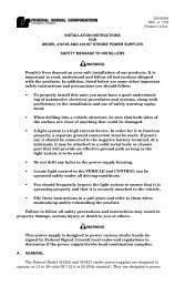
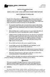
SAFETY MESSAGE TO INSTALLERS AND USERS<br />
People’s lives depend on your safe installation of our products. It<br />
is important to read, understand and follow all <strong>instruction</strong>s shipped<br />
with the products. In addition, listed below are some other important<br />
safety <strong>instruction</strong>s and precautions you should follow:<br />
• To properly install this <strong>light</strong>: you must have a good<br />
understanding of automotive electrical procedures and<br />
systems, along with proficiency in the installation and<br />
use of safety warning equipment.<br />
• DO NOT install equipment or route wiring in the<br />
deployment path of an air bag.<br />
• When drilling into a vehicle structure, be sure that both<br />
sides of the surface are clear of anything that could be<br />
damaged.<br />
• In order <strong>for</strong> the <strong>light</strong> to function properly, a separate<br />
ground connection must be made. If practical, it should<br />
be connected to the negative battery terminal. At a<br />
minimum, it may be attached to a solid metal body or<br />
chassis part that will provide an effective ground path<br />
as long as the <strong>light</strong> system is to be used.<br />
• Locate <strong>light</strong> control so the VEHICLE and CONTROL<br />
can be operated safely under all driving conditions.<br />
• Do not attempt to activate or deactivate <strong>light</strong> control<br />
while driving in a hazardous situation.<br />
• You should frequently inspect the <strong>light</strong> to ensure that it<br />
is operating properly and that it is securely attached to<br />
the vehicle.<br />
• File these <strong>instruction</strong>s in a safe place and refer to them<br />
when maintaining and/or reinstalling the product.<br />
Failure to follow all safety precautions and <strong>instruction</strong>s may<br />
result in property damage, serious injury, or death to you or others.<br />
A. GENERAL.<br />
The Model GS5 is a high-intensity strobe head designed <strong>for</strong> <strong>flush</strong><br />
<strong>mount</strong>ing on a vehicle’s exterior. It is designed <strong>for</strong> use with the <strong>Federal</strong><br />
Model SPS8 strobe power supply. The Model SPS8 is an eight head<br />
power supply rated at 75 quadruple flashes per minute and provides<br />
the following options: fast flash pattern, primary, secondary, and<br />
reduced power mode.<br />
B. INSTALLATION.<br />
WARNING<br />
This product is intended <strong>for</strong> use in a primary warning <strong>light</strong><br />
system. The strobe heads can ONLY be powered by the Model<br />
SPS8 power supply. Consult local codes and regulations to<br />
determine if the power supply/strobe head combination<br />
complies.<br />
NOTE<br />
For maximum coverage and effectiveness, the <strong>light</strong> assembly<br />
should be <strong>mount</strong>ed in a horizontal orientation in pairs: one in<br />
front and one to the side.<br />
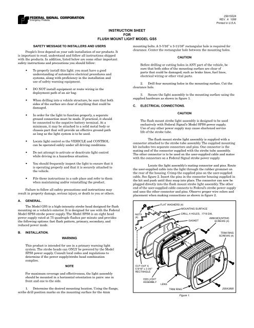
1. Determine the desired <strong>mount</strong>ing location. Using the flange,<br />
scribe drill position marks on the <strong>mount</strong>ing surface <strong>for</strong> the 4mm<br />
INSTRUCTION SHEET<br />
FOR<br />
FLUSH MOUNT LIGHT MODEL GS5<br />
2561552A<br />
REV. A 1099<br />
Printed in U.S.A.<br />
<strong>mount</strong>ing bolts. A 5-7/16" x 3-11/16" rectangular hole is required <strong>for</strong><br />
clearance. Center the rectangular hole between the <strong>mount</strong>ing holes.<br />
CAUTION<br />
Be<strong>for</strong>e drilling or cutting holes in ANY part of the vehicle, be<br />
sure that both sides of the <strong>mount</strong>ing surface are clear of<br />
parts that could be damaged; such as brake lines, fuel lines,<br />
electrical wiring or other vital parts.<br />
2. Drill four <strong>mount</strong>ing holes in the <strong>mount</strong>ing surface. Cut the<br />
clearance hole.<br />
3. Secure the <strong>light</strong> assembly to the <strong>mount</strong>ing surface using the<br />
supplied hardware as shown in figure 1.<br />
C. ELECTRICAL CONNECTIONS.<br />
CAUTION<br />
The <strong>flush</strong> <strong>mount</strong> strobe <strong>light</strong> assembly is designed to be used<br />
exclusively with <strong>Federal</strong> <strong>Signal</strong>’s Model SPS8 power supply.<br />
Use of any other power supply may cause shortened service<br />
life of the strobe tube.<br />
The <strong>flush</strong> <strong>mount</strong> strobe <strong>light</strong> assembly is supplied with a<br />
connector attached to the strobe tube assembly. The supplied <strong>mount</strong>ing<br />
kit includes two separate connectors and pins. One connector is the<br />
mating end of the connector supplied with the strobe tube assembly.<br />
The other connector is to be used on the user-supplied cable and mates<br />
with the connectors on a <strong>Federal</strong> <strong>Signal</strong> strobe power supply.<br />
Locate the <strong>light</strong> assembly’s mating connector and pins. Route<br />
the user-supplied cable into the <strong>light</strong> through the rubber grommet on<br />
the rear of the housing. Crimp the supplied pins on the user-supplied<br />
cable. See figure 2. Insert the pins in the connector housing supplied in<br />
the kit and push until they snap into place. The connector can now be<br />
plugged directly into the <strong>flush</strong> <strong>mount</strong> strobe <strong>light</strong> assembly. The other<br />
end of the user-supplied cable connects to <strong>Federal</strong>’s strobe power supply<br />
and uses the other connector and pins. Observe proper wire colors and<br />
placement when making connections as shown in figure 2.<br />
NUTS<br />
(4)<br />
CUT OUT A<br />
5 9/16" x 3 3/4"<br />
RECTANGLE<br />
GS5 LIGHT<br />
ASSEMBLY<br />
FLAT WASHERS (4)<br />
LENS<br />
TRIM RING<br />
MOUNTING SURFACE<br />
DRILL 4 HOLES, .1718 DIA.<br />
Figure 1.<br />
GASKET<br />
4MM MOUNTING<br />
SCREWS (4)<br />
TRIM RING<br />
SCREWS (4)<br />
290A3868
D. MAINTENANCE.<br />
1. General.<br />
WARNING<br />
Crazing (cracking) of lenses will cause reduced effectiveness<br />
of the <strong>light</strong>. Do not use cleaning agents (which will cause<br />
crazing) such as strong detergents, solvents, or petroleum<br />
products. If crazing of lenses does occur, reliability of <strong>light</strong> <strong>for</strong><br />
emergency signaling purposes may be reduced until lenses<br />
are replaced.<br />
Ordinary cleaning of the plastic lenses can be accomplished<br />
by using mild soap and a soft rag. Should fine scratches or a haze<br />
appear on a lens, they can ordinarily be removed with a non-abrasive,<br />
high quality, one-step, automotive paste cleaner/wax and a soft cloth.<br />
2. Strobe Tube Assembly Replacement.<br />
WARNING<br />
High voltage are present in a strobe <strong>light</strong> system. Wait at<br />
least five (5) minutes, after shutting off power, be<strong>for</strong>e<br />
servicing the unit. Failure to do so may result in property<br />
damage, serious injury, or death to you and others.<br />
a. Disconnect all power to the strobe system power supply<br />
be<strong>for</strong>e per<strong>for</strong>ming any maintenance.<br />
b. See figure 3. Remove and retain the four screws which<br />
secure the trim ring and lens. Carefully pull the trim ring and lens<br />
straight away from the <strong>flush</strong> <strong>mount</strong> <strong>light</strong> assembly.<br />
c. Remove the three screws which secure the strobe tube<br />
reflector. Remove the strobe tube reflector by pulling it straight away.<br />
d. Remove the four screws which secure the strobe<br />
assembly <strong>mount</strong>ing brackets.<br />
e. Disconnect the strobe tube reflector assembly from the<br />
cable assembly.<br />
CAUTION<br />
Service life of strobe tube will be shortened if glass is<br />
touched. If glass has been handled, clean carefully with a<br />
grease solvent.<br />
f. Install the strobe assembly <strong>mount</strong>ing brackets using<br />
the previously removed screws.<br />
STRIP<br />
CRIMP<br />
INSERT<br />
FROM<br />
USER<br />
SUPPLIED<br />
CABLE<br />
RED<br />
WHT<br />
BLK<br />
RED<br />
CONNECT<br />
DIRECTLY TO<br />
STROBE FLUSH<br />
MOUNT LIGHT ASSEMBLY<br />
Figure 2.<br />
WHT<br />
1 2 3<br />
BLK<br />
CONNECT<br />
DIRECTLY TO<br />
POWER SUPPLY<br />
FROM<br />
USER<br />
SUPPLIED<br />
CABLE<br />
290A3869<br />
-2-<br />
STROBE TUBE<br />
ASSEMBLY<br />
MTG.BRACKET<br />
STROBE TUBE<br />
MOUNTING<br />
SCREWS(6)<br />
STROBE TUBE<br />
ASSEMBLY<br />
GS5 LIGHT<br />
ASSEMBLY<br />
TRIM RING<br />
SCREWS(4)<br />
Figure 3.<br />
STROBE TUBE<br />
ASSEMBLY<br />
MTG.BRACKET<br />
LENS<br />
g. Connect the new strobe tube reflector assembly’s<br />
connector to the cable.<br />
TRIM RING<br />
290A3870<br />
h. Install the new strobe tube reflector assembly in the<br />
rear housing using the previously removed screws.<br />
i. Replace the trim ring and lens and secure with the<br />
previously removed screws.<br />
j. Reconnect all power connections to the power supply<br />
and test <strong>for</strong> proper operation.<br />
E. REPLACEMENT PARTS.<br />
Description Part No.<br />
Strobe Tube Reflector Assy., VAMA 8575167A<br />
Lens, Blue, Fluted 8575095-01<br />
Lens, Red, Fluted 8575095-03<br />
Lens, Amber, Fluted 8575095-05<br />
Lens, Clear, Fluted 8575095-07<br />
Lens, Green, Fluted 8575095-09<br />
Gasket, Lens 8575096<br />
Gasket, Flange 8575097<br />
SAFETY MESSAGE TO OPERATORS<br />
Peoples’ lives depend on your safe use of our products. Listed<br />
below are some important safety <strong>instruction</strong>s and precautions you<br />
should follow:<br />
• Although your warning system is operating properly, it<br />
may not be completely effective. People may not see or<br />
heed your warning signal. You must recognize this fact<br />
and continue driving cautiously.<br />
• Also, situations may occur which obstruct your warning<br />
signal when natural or man-made objects are between<br />
your vehicle and others, such as: raising your hood or<br />
trunk lid. If these situations occur, be especially careful.<br />
• At the start of your shift, you should ensure that the<br />
<strong>light</strong> is securely attached and operating properly.<br />
• Failure to follow these safety precautions may result in<br />
property damage, serious injury, or death to you, to<br />
passengers, or to others.<br />
RETAIN AND REFER TO THIS MESSAGE