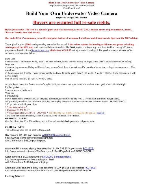
Build Your Own Underwater Video Camera - Underwater Projects ...
Build Your Own Underwater Video Camera - Underwater Projects ...
Build Your Own Underwater Video Camera - Underwater Projects ...

You also want an ePaper? Increase the reach of your titles
YUMPU automatically turns print PDFs into web optimized ePapers that Google loves.
<strong>Build</strong> <strong>Your</strong> <strong>Own</strong> <strong>Underwater</strong> <strong>Video</strong> <strong>Camera</strong><br />
http://underwaterprojects.741.com/index.html<br />
Free Downloads!<br />
<strong>Build</strong> <strong>Your</strong> <strong>Own</strong> <strong>Underwater</strong> <strong>Video</strong> <strong>Camera</strong><br />
Improved Design 2007 Edition<br />
Buyers are granted full re-sale rights.<br />
Buyers please note: The web is a dynamic place and so is the business world. URL's chance and so do part numbers, prices...<br />
I have no control over such events.<br />
Also in the USA it's customary to use decimal point instead of a comma. I also have added some metric figures to the 2007 edition.<br />
The original project (2004) end up costing more than I expected. I have since redone the housing as this one was prone to leaking.<br />
And replaced the RFU unit with newer and cheaper models. The 2004 project employed spy cam from Weldex costing $70, future<br />
projects used models from Supercircuits.com which start at $11.95, wiring remained unchaged. For good results go with one of the<br />
spy cams recommended below.<br />
Parts List:<br />
8 infrared led's/ or 4 bright white, plus 1, 59 ohm resistor, one of the best source of bright white led's is eBay seller will try selling<br />
large lots<br />
try contacting them see if they will breakdown some of their lots. Also ask specific questions about size, voltage, luminescence... The<br />
ones I use<br />
in the example are 3 Volts, if your power supply feeds out 12 volts, you'll need 4 (12 Volts / 3 Volts = 4 led's), if you are using a 9 volt<br />
power supply<br />
then all you'll need is 3 (9 volts / 3 volts=3 led's)<br />
Acrylic Lens, make one from a sheet of acrylic, or if you plan to use your camera in shallow water grab a lens off a flashlight.<br />
Rubber gasket<br />
Spacers, screws/ Bolts, nuts<br />
Wire ties<br />
Shrink tubing<br />
Down cable Home Depot sells 22/4 shielded communications cable by the foot, 21 cents/foot last time I bought some.<br />
All you really need for this camera is 24/2, but I'm hoping to use the other two conductors in future project. SKEW# 249605<br />
2 12 ga. wires and alligator clips<br />
1 5 lug terminal strip *<br />
1 Capacitor 47 Mf 25 v *<br />
1 Voltage regulator (JM24AF) LM2940T * don't buy the last 3 parts if you decide to use a dc adapter<br />
1 1/2 inch slip nut and washer, Moen plastic sn 2698c find it at Home Depot<br />
OPTIONAL PARTS<br />
One fast blow fuse 12 v 500 miliamp and holder and a switch both go on the red power wire.<br />
CAMERA UNITS<br />
The following units can be used in this project.<br />
BW camera .03 LUX part number WDH2500B standard lens<br />
http://www.spytown.com/welbwboarcam.html<br />
with 3.6mm lens. $55.00 plus shipping<br />
Alternate BW camera slightly less sensitive .1 LUX $39.95 Supercircuits PC212XS<br />
http://www.supercircuits.com/?txtSearch=pc212xs&PageAction=PRODSEARCH<br />
Color camera .5 LUX part number KPCS20C B standard lens<br />
http://www.spytown.com/worsmalsupmi1.html<br />
with 3.7mm lens. $119.00 plus shipping<br />
Alternate Color camera slightly less sensitive .8 LUX $69.95 Supercircuits PC213XS<br />
http://www.supercircuits.com/?txtSearch=pc213xs&PageAction=PRODSEARCH<br />
Getting Started<br />
http://freepistonjetengine.741.com
<strong>Camera</strong> Housing<br />
To fabricate the camera lens buy a sheet of clear acrylic cut it with a 1<br />
7/8 (48 mm) MASTER MECHANIC circle cutter . You'll find one of<br />
these at True Value Hardware Stores , in the USA. If you can not find<br />
one of these where you live, try cutting your circle with a jigsaw. To cut<br />
the lens using the circle cutter you'll also need a drill press, as these circle<br />
cutter will slip ruining your piece.<br />
You'll need a section of PVC pipe about 1" , a trap adapter, and an end<br />
cap. Glue the end pieces together in the order shown. Drill a hole in the<br />
center of the end cap, and slip the down wire through. Secure it by looping<br />
a wire tie and pull it tight. Using marine grade goop squeeze a bead<br />
between the wire and the end cap. This will make the housing water tight.<br />
To ensure against any possible leakage<br />
mix together 5 minute epoxy and pour it inside the end cap.<br />
Using a 1 1/2" circle cutter cut off two circles from the same acrylic sheet<br />
you used earlier for the lens. This circle cutter can be any brand, unlike the<br />
one used for cutting the lens.<br />
Next place the two pieces on top of each other, drill two holes diametrically opposed. Then take one of the parts and bore a larger hole<br />
using the center hole as a guide. This hole needs to be large enough for the camera lens to portude through. By now you must have<br />
picked up your LED's. Depending on the amount of LED's used drill a radial pattern on the same piece. If you are not sure which drill<br />
bit to use for this get a hold of a drill guide. Insert the LED's so that the leads line up long to short to long... and solder them following<br />
the wiring diagram on top. In the center of this array you should have soldered a resistor, you can place it anywhere but placing it here<br />
makes your project look neater, and less prone to short circuit.<br />
http://freepistonjetengine.741.com<br />
You spy cam should have included a bracket like the<br />
one in the picture on the left. Cut two slits on the part<br />
you set aside to acomodate the bracket.<br />
at this time drill a hole big enough to insert 5<br />
conductors through.<br />
Take a red and a black solder them to the LED array<br />
follow the wiring diagram. Black should be soldered<br />
to the short lead.<br />
Using two long screws and two sections of tubing as<br />
spacers join the two acrylic disks as in the picture.<br />
Last solder all the wires following the scematics<br />
below. Insert shrink tubing in all exposed wires and<br />
seal them by applying heat on the tubing. Thread the<br />
adapter cap using pipe compound. You are now done.
The camera was suspended by it's own power cable. A bracket was<br />
manufactured out of a 3 1/2" corner L brace for this purpose. The brace was cut<br />
off approximately 1 1/2" from the corner. The short end was bent up and the<br />
sharp edge filed smooth, the same was done to the edge on the sawed off piece.<br />
The small straight piece was then bolted to the bent up end of the L piece. Next<br />
two holes were drilled on the small piece. Two hose clamps were slipped over<br />
the housing and the bracket was inserted under both, (the long side of the<br />
bracket lays flat against the housing) and fastened by turning both screws . Two<br />
wire ties were inserted in the small holes drilled in the movable part, and the<br />
wire was attached by looping the ties around the cable and pulling the ends<br />
tightly. Enough slack was left as to allow the movable part of the bracket to be<br />
adjusted in any direction, this enables the camera to point up or down.<br />
An alternative would be an aluminum strap bracket. To build, cut it, and bend it to wrap the PVC housing snugly, drill a hole on the<br />
top end and get a length of the same material and drill 3 more holes on it, two at both ends. You next insert a bolt trough the strap and<br />
flat bar, tighten with a nut. The remaining holes are for wire ties you'll need them to secure the down wire to the bracket. At this point<br />
you'll drill a hole in the PVC housing large enough to insert the down wire. Look at the next picture for details.<br />
PUTTING IT ALL TOGETHER<br />
Electronics<br />
If you find these blueprints intimidating go on to my next project. It uses a power adapter.<br />
<strong>Your</strong> finished camera should look like this! The white wire on the<br />
threads is the microphone cable not used for this project. As tested<br />
this camera did not need any extra weight to sink. I did have<br />
problems with leaks and future projects used a fixed window and a<br />
cleanout adapter to access the camera. See tyco camera for details.<br />
First start by building your PVC housing. Then drill a hole slightly larger than the downwire. Next insert the downwire through the hole<br />
LED Array<br />
Disregard this section if you intend to use an external light source, such as sunlight, flashlight... Flashlights are much easier to use and<br />
provide more<br />
more light. <strong>Underwater</strong> Kinetics has several inexpensive watertight flashlights at reasonable prices. These camera are perfect for our<br />
project as they come with two places where one can loop hose clamps and attach it to the underwater camera housing. Wire ties may<br />
also be used to secure the flashlight.<br />
http://freepistonjetengine.741.com
Picture shows two flaslights<br />
Check out www.uwkinetics.com<br />
<strong>Underwater</strong> Kinetics<br />
13400 Danielson St<br />
Poway, CA 92062<br />
USA<br />
1.800.327.7388<br />
Bright white LED's are rated for 3 volts. One lead is longer than the other, this is how you<br />
can tell their polarity.<br />
Make sure you mark where the short and long leads start, the difference is almost<br />
indistinguishable. the drawing of the left shows a 4 LED installation (3voltsX 4 LED's =<br />
12Volts). Infrared LED's put out invisible light which can only be picked up by the camera.<br />
Infrared LED's are rated between 1.2 and 1.6 volts (1.5), they are also about half the price of<br />
bright white type. <strong>Build</strong>er cand double the number of infrared LED's to 8, as in the example<br />
below.<br />
First you must drill a hole in PVC housing for the downwire. Hole should be only slightly<br />
larger than cable. Then slip the wire through the hole next fasten a wire tie to cable about 3<br />
inches from end.<br />
Now strip insulation off 2 1/2 from end. Mix a batch of 5 minute epoxy and dab onto wire<br />
below wire tie. Pull wire back into PVC housing and let the epoxy cure according to<br />
manufacturer recommendation. This makes your camera water proof. As a safety precaution I<br />
squeeze in some silicone caulk or other sealent on the outside. Epoxy may crack if the cable is<br />
tugged too hard or the camera is dropped... Silicone sealant is flexible and hold up better. See<br />
my other ebooks for other ways to make your camera watertight.<br />
The LED marke L for long is soldered to the red conductors and the blue cable. Yellow<br />
connects to the white cable and the braided shield is soldered to the last remaining conductor,<br />
in our case it's a braided shield.<br />
http://freepistonjetengine.741.com
Lug 1 Not used<br />
Lug 2 +12v Power source<br />
Lug 3 Ground<br />
Lug 4 Power out camera, RFU Unit<br />
Lug 5 <strong>Video</strong> junction<br />
Connecting <strong>Your</strong> <strong>Camera</strong> To A Monitor<br />
Connecting To A Television Receiver<br />
(Tv Set)<br />
If you are planning to use a VCR or similar recording device, then all you need do is plug the RCA jack to the back of such device.<br />
Most portable Tv sets don't come equiped with RCA plugs. You must purchase one of the following RFU modulators at Walmart and<br />
follow the schematics. Please note all RFU modulators will do the job. These are very inexpensive the first example cost me $10 and the<br />
second $7. The last one being small enough that it was incorporated into the project box.<br />
If you use an old tv without a threaded coaxial cable female plug, open up the PL-303 unit and using your soldering iron, remove the<br />
antenna input, then solder two wires, one to the center, the second to the flange, use a few layers of electrical tape on the soldered ends.<br />
Next connect the ends of the two wires to the antenna connections on the back of the tv.<br />
Caution not all RFU units are created equal, even when they come from the same manufacturer. Pelican 7020 has 3 conductors, the red<br />
wire is your ground, the green positive 5 volts, yellow video in. To assemble this cut off the plug (do not cut off the ferrite) and strip off<br />
the insulation, exposing the conductors. drill a hole in your control unit and slip the wire through. secure the cable with a wire tie. solder<br />
the output from the adapter to the red and green wires, next solder the video cable to the yellow conductor. Don't forget to insulate all<br />
solder connections with heat shrink tubing. The powering options above apply to this model.<br />
http://freepistonjetengine.741.com
Improved Housing (leak proof)<br />
The camera housing consisted of a section of 1 1/2 inch PVC pipe<br />
(a), 5 inches long. One 1 1/2 inch cleanout adapter (b), and a union<br />
joint (c) cut nearly in half, one section must have the inner lip intact<br />
(d).<br />
The assembly of the housing: A bead of black silicone was squirted<br />
on one of the pipe's edges and the lexan window placed on top (f).<br />
The union section with the lip was similarly treated with a bead of<br />
silicone on the inner side of the lip.<br />
Next Place the pipe on a table with the lens side up. clean the upper<br />
section and apply PVC adhesive, quckly force the union joint down,<br />
until it stops. Within a few seconds the clean out adapter can also be<br />
glued.<br />
The housing was tested using a spare clean out cap. The housing was weighed down using a brick<br />
and trown into a pool overnight. A lens protector was attached to the housing (a plastic cap off an empty snack food container) to<br />
protect the lens from abrasion.<br />
This is a housing built of 2 1/2 pipe.<br />
same principle shorter section of pipe. Picture on left was taken<br />
during construction. I inserted the spycam inside to make sure it<br />
would fit. Should your camera not fit inside 1 1/2" pipe try larger<br />
pipe.<br />
http://freepistonjetengine.741.com
Top left: Shows the finished product. The lens retainer was<br />
later sanded down flush with edge.<br />
Top right: Control box and camera.<br />
Left: Control box open .<br />
Bottom left: Housing finished and painted.<br />
Next you must fabricate a bracket like the one shown in the pictures<br />
below. Choose an aluminum strap that is easily bent. See<br />
accompanying file on the Tyco camera for details on making your<br />
own bracket. The picture sequence below shows the camera pointing<br />
up to check hulls, piers, docks, bridges... The middle picture shows<br />
the camera pinting down to check bottom of a river, ocean, well...<br />
Last picture shows the camera pointing straight for cruising, trolling...<br />
http://freepistonjetengine.741.com
Before taking the finished camera to the local pond, river or sea,<br />
squirt some pipe dope on the housings threads. Pipe dope protects<br />
against leaks up to 10,000 PSI.<br />
All you need now is a cheap portable Tv. Connect the RFU's<br />
coaxial cable to the back of your set. Some small Tv's don't have a<br />
coaxial cable connection. Instead they have an jack connection<br />
similar to an audio plug. An adapter is all you need.<br />
http://freepistonjetengine.741.com<br />
http://underwaterprojects.741.com/index.html<br />
Free Downloads!<br />
Buyers are granted full re-sale rights.