Formulation and Implementation of a Methodology for Aircraft - Pace
Formulation and Implementation of a Methodology for Aircraft - Pace
Formulation and Implementation of a Methodology for Aircraft - Pace

You also want an ePaper? Increase the reach of your titles
YUMPU automatically turns print PDFs into web optimized ePapers that Google loves.
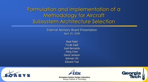
<strong>Formulation</strong> <strong>and</strong> <strong>Implementation</strong> <strong>of</strong> a<br />
<strong>Methodology</strong> <strong>for</strong> <strong>Aircraft</strong><br />
Subsystem Architecture Selection<br />
External Advisory Board Presentation<br />
April 29, 2009<br />
Neal Patel<br />
Turab Zaidi<br />
José Bernardo<br />
Peng Chen<br />
David Jackson<br />
Sehwan Oh<br />
Edward Tsai<br />
Aerospace System Design Laboratory<br />
Georgia Institute <strong>of</strong> Technology
“Engineering has has taken taken us us to to a a stage stage where where we we are are beginning to to rationalize <strong>and</strong> <strong>and</strong><br />
reintegrate things things that that we we have have spent spent many many decades separating <strong>and</strong> <strong>and</strong> ‘optimizing.’<br />
Now, Now, the the potential <strong>of</strong> <strong>of</strong> science can can enable enable us us to to take take the the next next step step in in this this journey.”<br />
2<br />
Lester Faleiro<br />
Project Manager, Power Optimized <strong>Aircraft</strong>
The EOASys<br />
Initiative<br />
The Installation<br />
Problem<br />
Outline<br />
Architecture<br />
Selection<br />
<strong>Methodology</strong><br />
3<br />
The Pro<strong>of</strong><br />
<strong>of</strong> Concept<br />
Pro<strong>of</strong> <strong>of</strong><br />
Concept Demo<br />
Concluding<br />
Remarks
Dr. Dr. Dimitri DimitriMavris Mavris<br />
Faculty<br />
Faculty<br />
Sponsor<br />
Sponsor<br />
José JoséBernardo Bernardo<br />
Program Organization<br />
Neal Neal Patel Patel<br />
Project<br />
Project<br />
Manager<br />
Manager<br />
Dr. Dr. Elena Elena Garcia Garcia<br />
Project<br />
Project<br />
Advisor<br />
Advisor<br />
Turab TurabZaidi Zaidi<br />
Chief<br />
Chief<br />
Engineer<br />
Engineer<br />
4<br />
Dr. Dr. Neil Neil Weston Weston<br />
Project<br />
Project<br />
Advisor<br />
Advisor<br />
Mathias Mathias Emeneth Emeneth<br />
PACE<br />
PACE<br />
Consultant<br />
Consultant<br />
Peng Chen David Jackson Sehwan Oh Oh Edward Tsai Tsai
The EOASys<br />
Initiative<br />
The EOASys Initiative<br />
The Installation<br />
Problem<br />
Architecture<br />
Selection<br />
<strong>Methodology</strong><br />
5<br />
The Pro<strong>of</strong><br />
<strong>of</strong> Concept<br />
Pro<strong>of</strong> <strong>of</strong><br />
Concept Demo<br />
Concluding<br />
Remarks
• What is an energy optimized aircraft?<br />
Energy Optimized <strong>Aircraft</strong> Initiative<br />
– One that manages energy flows to achieve the most reduction in peak<br />
nonpropulsive power usage, while obtaining the best compromise in<br />
fuel consumption <strong>and</strong> equipment weight<br />
• Major Obstacles<br />
– <strong>Aircraft</strong> <strong>of</strong> the future must adapt to changing power requirements 1<br />
– Rising power dem<strong>and</strong>s have led to greater system complexity<br />
– Increasing fuel costs <strong>and</strong> environmental concern<br />
• AIAA EOASys Program Committee<br />
– Seeks comprehension <strong>of</strong> technical issues facing <strong>Aircraft</strong> Equipment Systems (AES) 1<br />
– AES are the systems “hidden under the floor, inside wings, <strong>and</strong> behind panels” 1<br />
– This includes avionics, hydraulic actuators, electric cables, etc.<br />
6<br />
Boeing 787 will<br />
require 1 MW <strong>of</strong><br />
electric power
• Current ef<strong>for</strong>ts emphasize developing more<br />
electric technologies<br />
– Components optimized individually by vendors<br />
• Majority <strong>of</strong> issues arise during system integration<br />
– New technologies <strong>of</strong>ten physically swapped in<br />
– Organization <strong>of</strong> AES affects overall subsystem efficiency<br />
• Interactions <strong>and</strong> constraints between<br />
components must be captured<br />
– In<strong>for</strong>mation should be leveraged to develop strategic<br />
AES installation<br />
– No environment exists to evaluate these types <strong>of</strong><br />
trade<strong>of</strong>fs during conceptual design<br />
Motivation<br />
7<br />
Old Components More Electric Components
The EOASys<br />
Initiative<br />
The Installation Problem<br />
The Installation<br />
Problem<br />
Architecture<br />
Selection<br />
<strong>Methodology</strong><br />
8<br />
The Pro<strong>of</strong><br />
<strong>of</strong> Concept<br />
Pro<strong>of</strong> <strong>of</strong><br />
Concept Demo<br />
Concluding<br />
Remarks
The Focused Problem: Installation<br />
• Full potential <strong>of</strong> new components may not be achieved<br />
in future aircraft<br />
• Current configurations may benefit from holistic re-<br />
integration/evaluation<br />
• Potential gains:<br />
– Minimizing system weight - Adding/removing cabling or<br />
hydraulic lines<br />
– Minimizing exergy loss - Maximum amount <strong>of</strong> available work<br />
– Managing energy flows - Efficiency fluctuation due to<br />
thermal effects<br />
9<br />
Minimizing Weight<br />
Minimizing Exergy Loss<br />
Investigation <strong>of</strong> new installation architectures is necessary<br />
Managing Energy Flow
What is an Installation Architecture?<br />
B<br />
Architecture 1 Architecture 2<br />
A<br />
C<br />
D<br />
Same components<br />
Different placement<br />
10<br />
B<br />
C<br />
A<br />
D
Program Objectives<br />
1. Formulate a generic methodology that allows designers to optimally install <strong>Aircraft</strong> Equipment Systems into an aircraft<br />
– <strong>Methodology</strong> facilitates installation <strong>of</strong> any subsystem or component<br />
2. Demonstrate methodology through a Pro<strong>of</strong> Of Concept (POC)<br />
– POC makes enabling assumptions to facilitate project scope<br />
– POC shows how the methodology can be used to improve component placement <strong>and</strong> realize aircraft level gains<br />
<strong>Methodology</strong> Pro<strong>of</strong> <strong>of</strong> Concept Program Results<br />
Enabling<br />
Assumptions<br />
11<br />
Architecture<br />
Selection
Architecture Selection <strong>Methodology</strong><br />
The EOASys<br />
Initiative<br />
The Installation<br />
Problem<br />
Architecture<br />
Selection<br />
<strong>Methodology</strong><br />
12<br />
The Pro<strong>of</strong><br />
<strong>of</strong> Concept<br />
Pro<strong>of</strong> <strong>of</strong><br />
Concept Demo<br />
Concluding<br />
Remarks
Step 1<br />
The Architecture Selection <strong>Methodology</strong><br />
Component Component Component Library<br />
Library<br />
Library<br />
Creation<br />
Creation<br />
Creation<br />
Step 2<br />
Sizing/Synthesis Sizing/Synthesis Sizing/Synthesis Sizing/Synthesis &<br />
&<br />
&<br />
&<br />
<strong>Aircraft</strong> <strong>Aircraft</strong> <strong>Aircraft</strong> <strong>Aircraft</strong> Zoning<br />
Zoning<br />
Zoning<br />
Zoning<br />
Step 3<br />
Step 4<br />
Component Component Placement<br />
Placement<br />
Placement<br />
Requirements<br />
Requirements<br />
Flow-down<br />
Flow-down<br />
Flow-down<br />
Flow-down<br />
Flow down down down<br />
Initial Initial Architecture<br />
Architecture<br />
Generation<br />
Generation<br />
13<br />
Step 5<br />
Step 6<br />
Investigate Investigate Investigate Competing<br />
Competing<br />
Competing<br />
Architectures<br />
Architectures<br />
Architectures<br />
Measures Measures Measures Measures <strong>of</strong> <strong>of</strong> <strong>of</strong> <strong>of</strong> Merit<br />
Merit<br />
Merit<br />
Merit<br />
Identification<br />
Identification<br />
Identification<br />
Identification
Step 1 – Component Library Creation<br />
• Method <strong>of</strong> library creation leveraged from previous<br />
Gr<strong>and</strong> Challenge Teams<br />
1.1 Select a primary function<br />
1.2 Identify induced functions<br />
1.3 Create matrix <strong>of</strong> alternatives <strong>of</strong> components<br />
1.4 Define basic connections between components<br />
1.5 Verify specific functions are met<br />
Output <strong>of</strong> Step 1<br />
A fixed list <strong>of</strong> components <strong>and</strong> basic<br />
connections to be installed<br />
14<br />
Primary Function<br />
Generate light<br />
Component List<br />
Induced Functions<br />
Provide electricity or ignite light source<br />
Component List
2.1 Select an aircraft geometry<br />
Step 2 – Sizing/Synthesis & <strong>Aircraft</strong> Zoning<br />
2.2 Acquire sizing <strong>and</strong> synthesis in<strong>for</strong>mation<br />
2.3 Zone the aircraft<br />
– Assists with capturing component placement constraints<br />
2.4 Specify possible connection routes<br />
Output <strong>of</strong> Step 2<br />
A fully defined <strong>and</strong> zoned aircraft geometry<br />
15
Step 3 – Placement Requirements Flow-down<br />
3.1 Find applicable system level constraints<br />
– FAA Federal Aviation Regulations (FAR)<br />
– Stability Limits<br />
– Volume Limits<br />
– Ease <strong>of</strong> maintenance<br />
3.2 Define applicable component level requirements<br />
– Temperature ranges, Electrical power <strong>and</strong> ratings,<br />
EMI control, System grounding, etc. 2<br />
3.3 Formulate zonal placement requirements<br />
Output <strong>of</strong> Step 3<br />
Constraints <strong>and</strong> requirements on component placement<br />
16<br />
Component<br />
Constraints Functional<br />
Requirements<br />
Component<br />
Placement<br />
Requirements
Step 4 – Initial Architecture Generation<br />
4.1 Select location <strong>of</strong> components<br />
within feasible zones<br />
– Use historical data when available<br />
4.2 Verify all requirements are met<br />
– Change component location when<br />
needed<br />
Output <strong>of</strong> Step 4<br />
Step 1<br />
Hydraulic<br />
Mechanic<br />
Electric<br />
Components<br />
Baseline aircraft with components<br />
placed to meet requirements<br />
17<br />
Sized <strong>Aircraft</strong><br />
Initial Configuration<br />
Step 2<br />
FAR<br />
Step 3<br />
Volume<br />
Power<br />
Zone<br />
Requirements
Step 5 – Measures <strong>of</strong> Merit Identification<br />
5.1 Identify relevant system level metrics<br />
– Metrics should be related to costs <strong>and</strong><br />
benefits<br />
5.2 Relate system level metrics to<br />
applicable installation metrics<br />
– Metrics have to be quantifiable<br />
5.3 Benchmark the initial architecture<br />
Output <strong>of</strong> Step 5<br />
Potential<br />
Architectures<br />
Metrics <strong>for</strong> comparison <strong>of</strong> different architectures<br />
18<br />
Installation<br />
Metrics<br />
Architecture C<br />
`<br />
Architecture B<br />
Architecture A<br />
System Level<br />
Metric Target
Step 6 – Investigating Competing Architectures<br />
6.1 Choose method to explore design space<br />
6.2 Implement exploration method<br />
– Requires development <strong>of</strong> modeling <strong>and</strong> simulation environment<br />
6.3 Per<strong>for</strong>m architecture trades<br />
– Based on weighting preferences on measures <strong>of</strong> merit<br />
Output <strong>of</strong> Step 6<br />
An optimized architecture based on<br />
customer preferences<br />
19
The EOASys<br />
Initiative<br />
The Pro<strong>of</strong> <strong>of</strong> Concept<br />
The Installation<br />
Problem<br />
Architecture<br />
Selection<br />
<strong>Methodology</strong><br />
20<br />
The Pro<strong>of</strong><br />
<strong>of</strong> Concept<br />
Pro<strong>of</strong> <strong>of</strong><br />
Concept Demo<br />
Concluding<br />
Remarks
• Need a plat<strong>for</strong>m to implement a methodology<br />
• No existing environment which captures<br />
component interactions<br />
• Several s<strong>of</strong>tware plat<strong>for</strong>ms were considered to create<br />
the design environment <strong>for</strong> the pro<strong>of</strong> <strong>of</strong> concept<br />
• Plat<strong>for</strong>m requirements:<br />
1. Provide a 3-D visual representation <strong>of</strong> component placement <strong>for</strong><br />
each architecture<br />
2. Easily populate components <strong>and</strong> connections into model<br />
3. Quickly generate multiple installation architectures<br />
4. Dynamically evaluate component characteristics <strong>and</strong> interactions<br />
5. Interact with other s<strong>of</strong>tware to incorporate existing codes<br />
6. Facilitate analysis <strong>and</strong> trades between architectures<br />
7. Provide direct links to s<strong>of</strong>tware support personnel<br />
• <strong>Pace</strong>lab APD was selected as best compromise<br />
Plat<strong>for</strong>m Selection<br />
21<br />
1<br />
2<br />
3<br />
4<br />
5<br />
6<br />
7<br />
ADEN CATIA Dymola Easy5 Excel JMP <strong>Pace</strong>lab APD Simulink<br />
Meets requirement<br />
Potentially meets requirement<br />
Did not meet requirement
Modeling & Simulation Environment<br />
• M&S environment was created in <strong>Pace</strong>lab<br />
<strong>Aircraft</strong> Preliminary Design (<strong>Pace</strong>lab APD)<br />
• Displays a 3D representation <strong>of</strong> the model<br />
• Unique s<strong>of</strong>tware plat<strong>for</strong>m focused on<br />
Knowledge Based Engineering<br />
• Allows mathematical definition <strong>of</strong> an aircraft<br />
<strong>and</strong> its internal structure<br />
• Acquisition <strong>of</strong> <strong>Pace</strong>lab APD was a key<br />
breakthrough <strong>for</strong> our design environment<br />
22
Step 1 – Component Library Creation<br />
• Only one primary function was demonstrated to limit the scope<br />
– Deliver electrical power to loads in the avionics bay<br />
• Function further limits the scope by reducing the number <strong>of</strong><br />
components modeled<br />
• The component list was created from the Maintenance Facility<br />
Planning (MFP) document <strong>and</strong> in<strong>for</strong>mation from Airbus component<br />
suppliers<br />
• Schematics in the MFP were used to define basic connections<br />
23<br />
IDG<br />
IDG<br />
AC AC Bus Bus 1<br />
1<br />
AC AC Essential Essential Bus<br />
Bus<br />
Avionics<br />
Avionics<br />
Loads<br />
Loads<br />
Other<br />
Other<br />
Electric<br />
Electric<br />
Components<br />
Components
Step 2 – Sizing/Synthesis & <strong>Aircraft</strong> Zoning<br />
• A320 chosen as the aircraft geometry <strong>for</strong> POC<br />
• Flight deck, passenger cabin, & cargo holds modeled in<br />
simulation environment<br />
• Feasible aircraft areas divided into five zones<br />
– Zones based on possible locations <strong>for</strong> components in library<br />
– Includes knowledge gained from Delta 737 overhaul<br />
• Feasible wiring route pathways generated <strong>for</strong> potential<br />
component connections<br />
24
Step 3 – Placement Requirements Flow-down<br />
• Requirements come from aircraft<br />
documentation <strong>and</strong> FAR<br />
– Operating Temperature<br />
– Required Power<br />
– Center <strong>of</strong> Gravity<br />
Operating<br />
Temperature<br />
<strong>Aircraft</strong> Documents Requirements<br />
B<br />
A<br />
C<br />
25<br />
Required<br />
Power<br />
B<br />
Center <strong>of</strong><br />
Gravity<br />
A<br />
C
Step 3 – Placement Requirements Flow-down<br />
• Requirements come from aircraft<br />
documentation <strong>and</strong> FAR<br />
– Operating Temperature<br />
– Required Power<br />
– Center <strong>of</strong> Gravity<br />
– Volume<br />
– Zones<br />
– Wire Routes<br />
Volume Zones<br />
Wire Routes<br />
26<br />
Fire Zone<br />
Cabin/Cargo Compartment<br />
A320 Cross Section<br />
General<br />
Wire Paths
Step 4 – Initial Architecture Generation<br />
• Comparing architectures <strong>and</strong> per<strong>for</strong>ming<br />
trades fundamentally requires a baseline<br />
– Initial configuration used <strong>for</strong> comparison to<br />
all other architectures<br />
• Initial placements <strong>and</strong> connections<br />
determined from Airbus documentation<br />
• Initial architecture input into<br />
<strong>Pace</strong>lab APD using Excel file<br />
27<br />
Initial Configuration
• Payload Capacity<br />
Step 5 – Measures <strong>of</strong> Merit Identification<br />
– Wire weight reduction allows a payload increase<br />
– Results in an increase in revenue<br />
• Fuel Weight<br />
– Varies depending on decrease in power drop<br />
due to temperature, wire length, efficiency<br />
– Results in decrease in operating fuel cost<br />
• Center <strong>of</strong> Gravity<br />
– Locations <strong>of</strong> components affect stability<br />
Method <strong>of</strong><br />
Calculation<br />
B<br />
B<br />
Locations <strong>of</strong> Components<br />
28<br />
A<br />
C<br />
A<br />
Wire Weight<br />
Power Extraction from engines<br />
B<br />
C<br />
POC<br />
Evaluator<br />
Payload Capacity<br />
Related<br />
System<br />
Level Metric<br />
$/RPM<br />
Fuel Weight Fuel Cost<br />
C.G.<br />
Stability
Step 6 – Investigating Competing Architectures<br />
• Many methods to identify competing architectures<br />
– Optimization methods<br />
– Design Space Exploration methods<br />
• Selected a Monte Carlo simulation combined with data<br />
post-processing<br />
• Investigation consists <strong>of</strong> three phases:<br />
– Pre-processing: Generating architectures<br />
– Processing: Running the modeling <strong>and</strong> simulation environment<br />
– Post-Processing: Analysis <strong>of</strong> the saved measures <strong>of</strong> merits<br />
29<br />
Run 1: Component 1: X1, Y1, Z1<br />
Component 2: X2, Y2, Z2<br />
Component 3: X3, Y3, Z3<br />
...<br />
Run 2: Component 1: X1, Y1, Z1<br />
Component 2: X2, Y2, Z2<br />
Component 3: X3, Y3, Z3<br />
...<br />
…<br />
Pre-processing:<br />
Pre-processing:<br />
Processing:<br />
Processing:<br />
Post-processing:<br />
Post-processing:<br />
Run 1: Results 1<br />
Results 2<br />
...<br />
Run 2: Results 1<br />
Results 2<br />
...<br />
…
The EOASys<br />
Initiative<br />
Pro<strong>of</strong> <strong>of</strong> Concept Demo<br />
The Installation<br />
Problem<br />
Architecture<br />
Selection<br />
<strong>Methodology</strong><br />
30<br />
The Pro<strong>of</strong><br />
<strong>of</strong> Concept<br />
Pro<strong>of</strong> <strong>of</strong><br />
Concept Demo<br />
Concluding<br />
Remarks
The EOASys<br />
Initiative<br />
Concluding Remarks<br />
The Installation<br />
Problem<br />
Architecture<br />
Selection<br />
<strong>Methodology</strong><br />
31<br />
The Pro<strong>of</strong><br />
<strong>of</strong> Concept<br />
Pro<strong>of</strong> <strong>of</strong><br />
Concept Demo<br />
Concluding<br />
Remarks
Conclusions<br />
• POC tool applies generic methodology to focused problem<br />
– Provides capability to dynamically <strong>and</strong> visually trade architectures<br />
– ‘Best’ design demonstrates fuel savings <strong>and</strong> increase in payload capacity <strong>for</strong><br />
small fraction <strong>of</strong> the AES<br />
• POC enables not only study <strong>of</strong> fixed aircraft <strong>and</strong> components:<br />
– Ability to create architectures with entirely new <strong>and</strong> varying component lists<br />
– New technologies can be input <strong>and</strong> explored early in design<br />
– With appropriate in<strong>for</strong>mation <strong>and</strong> knowledge base, entire AES can be studied<br />
This study serves as a stepping stone <strong>for</strong> future<br />
integration <strong>of</strong> energy optimized aircraft<br />
32<br />
New<br />
Technologies<br />
New Installation<br />
Architectures<br />
Holistic<br />
Integration<br />
<strong>of</strong> AES
Future Work<br />
• Modeling <strong>of</strong> more components <strong>and</strong> systems to realize a more complete perspective <strong>of</strong> the installation design space<br />
– Replacing hydraulic <strong>and</strong> pneumatic systems<br />
• Incorporate <strong>Pace</strong>lab APD’s sizing <strong>and</strong> synthesis<br />
– If aircraft could be scaled geometrically as in sizing <strong>and</strong> synthesis, benefits would be magnified<br />
• Requirements added to include different flight modes <strong>and</strong> failure modes<br />
• Exp<strong>and</strong> knowledge base with more accurate industry in<strong>for</strong>mation<br />
– Requirements <strong>and</strong> experience utilized <strong>for</strong> installation must be captured as rules <strong>and</strong> input<br />
– More comprehensive set <strong>of</strong> evaluators can be considered<br />
33
– Dr. Dimitri Mavris<br />
– Dr. Elena Garcia<br />
– Dr. Neil Weston<br />
– Michael Armstrong<br />
– Latessa Bortner<br />
– Bjorn Cole<br />
ASDL<br />
Acknowledgements<br />
– Cyril de Tenorio<br />
– Andrew Dunbeck<br />
– Kelly Griendling<br />
– Eric Hendricks<br />
– Hern<strong>and</strong>o Jimenez<br />
– Leon Phan<br />
34<br />
Delta<br />
– Livia Carneiro<br />
– Brian Duff<br />
– Charles Harkey<br />
PACE<br />
– Mathias Emeneth<br />
– Glenn Reis<br />
– Alex<strong>and</strong>er<br />
Schneegans