Case Study: Lufthansa CityLine | Aircraft IT Operations ... - Pace
Case Study: Lufthansa CityLine | Aircraft IT Operations ... - Pace
Case Study: Lufthansa CityLine | Aircraft IT Operations ... - Pace

You also want an ePaper? Increase the reach of your titles
YUMPU automatically turns print PDFs into web optimized ePapers that Google loves.
10 | CASE STUDY: LUFTHANSA C<strong>IT</strong>YLINE | AIRCRAFT <strong>IT</strong> OPERATIONS | SUMMER 2011<br />
therefore reached later. This situation is reversed for a low cost index (CI=0) or<br />
a low speed. The extra power of the engines results in a high climb angle, so<br />
that the cruise altitude is reached earlier. Both cases have implications for the<br />
subsequent cruise segment and the overall flight time.<br />
In the case of the descent segment, a higher cost index (higher flight speed)<br />
leads to a steeper angle of descent, whereas a lower cost index (slower flight<br />
speed) allows for a gentler angle of descent. Like the climb segment, there are<br />
implications to the cruise segment. A steep and short descent results in a longer<br />
cruise segment at the optimum altitude.<br />
It is important to note that for each parameter set comprised of take-off weight<br />
(TOW), CI, distance and wind there is a particular combination of optimum<br />
altitude and optimum speed triple, where ‘speed triple’ denotes a particular<br />
combination of climb, cruise and descent speed values. The figure below shows<br />
such a speed triple for an example parameter set with an altitude restriction (Alt<br />
Cap) on FL340 as a point in three-dimensional space.<br />
Each time the parameters are changed, the position of the point changes in<br />
this space, making rule of thumb estimates impossible.<br />
CI OPS USE In COCKP<strong>IT</strong><br />
<strong>Lufthansa</strong> <strong>CityLine</strong> uses so called Class 2 EFB systems in the cockpits of their<br />
Canadair and Embraer Jets. Class 2 EFB systems are generally commercialoff-the-shelf<br />
(COTS) based computer systems used for aircraft operations.<br />
They are portable and connected to aircraft power through a certified power<br />
source. The Class 2 EFB system is considered as a controlled personal electronic<br />
device (PED) and is connected to an aircraft mounting device during normal<br />
operations. Moreover connectivity to Avionics is possible, but the systems<br />
require airworthiness approval.<br />
PERFORmIng CALCULATIOnS In CI OPS<br />
COCKP<strong>IT</strong> PREPARATION (PREP)<br />
Before flight, the <strong>Pace</strong>lab CI OPS must be initialized with basic flight mission<br />
and weather data. These data can be supplied using an eOFP or by manually<br />
entering the required data.<br />
After having entered all data necessary for calculating the optimum trajectory,<br />
the ‘Calculate’ button can be used for a first optimum trajectory be calculated.<br />
The trajectories calculated in PREP are not time constrained and therefore<br />
correspond to the most economical trajectory with regard to the total costs<br />
(time and fuel).<br />
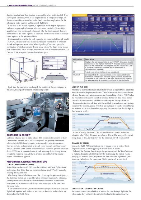
In the results window the (non-time constrained) trajectory for even and odd<br />
flight levels together with additional information about fuel and total cost are<br />
displayed in the Profile View:<br />
LINE-UP (T/O 60S)<br />
After line-up clearance has been obtained and take-off is expected to be initiated in<br />
about 60 seconds, the pilot can click the ‘T/O 60s’ Button on the action toolbar to<br />
calculate the optimum trajectory considering the actual take-off time. CI OPS takes<br />
the system time and adds 60 seconds to estimate the take-off time. Based on this<br />
take-off time, the application calculates the trajectory and displays the results.<br />
By comparing the take-off time with the on-block time, delays or early-in-timescenarios<br />
(for example, caused by slot or taxi-out delay or shorter taxi-out times)<br />
are included in the time dependent trajectory. The time window for the flight is<br />
thus larger or smaller.<br />
In case of a delay, <strong>Pace</strong>lab CI OPS will modify the CI up to a maximum<br />
allowable value. When this value is reached, a delay will be accepted. In case of<br />
being ahead of time, the trajectory for the minimum CI will be calculated.<br />
CHANGE OF SPEED<br />
During the flight, ATC might advise you to change speed in cruise. This is<br />
frequently caused by the staggering of aircraft ahead or behind.<br />
Following the fact that there is a specific optimum speed, the ‘Speed’ use case<br />
is available. In addition to the trajectory for maintaining the current FL and<br />
applying the required speed, trajectories for four additional flight levels (two<br />
above, two below) and the appropriate ECON speeds will be calculated.<br />
DELAYED OR TOO EARLY IN CRUISE<br />
Because of various external effects, it is often the case during a flight that the<br />
pilots realize they will arrive too early (or too late) at the destination. The