How to assemble the Hoffman Amps bias current ... - Mojotone.com
How to assemble the Hoffman Amps bias current ... - Mojotone.com
How to assemble the Hoffman Amps bias current ... - Mojotone.com

Create successful ePaper yourself
Turn your PDF publications into a flip-book with our unique Google optimized e-Paper software.
<strong>How</strong> <strong>to</strong> <strong>assemble</strong> <strong>the</strong> <strong>Hoffman</strong><br />
<strong>Amps</strong> <strong>bias</strong> <strong>current</strong> checkers<br />
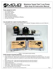
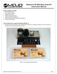
The Bias Checker Parts<br />
The tube bases with <strong>the</strong> wire hole already drilled and a nice<br />
gold sticker<br />
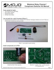
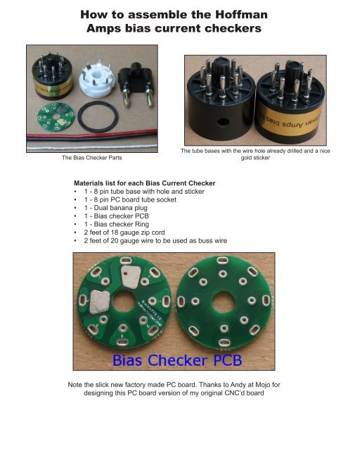
Materials list for each Bias Current Checker<br />
• 1 - 8 pin tube base with hole and sticker<br />
• 1 - 8 pin PC board tube socket<br />
• 1 - Dual banana plug<br />
• 1 - Bias checker PCB<br />
• 1 - Bias checker Ring<br />
• 2 feet of 18 gauge zip cord<br />
• 2 feet of 20 gauge wire <strong>to</strong> be used as buss wire<br />
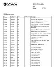
Note <strong>the</strong> slick new fac<strong>to</strong>ry made PC board. Thanks <strong>to</strong> Andy at Mojo for<br />
designing this PC board version of my original CNC’d board
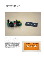
Assembled <strong>bias</strong> checkers<br />
<strong>How</strong> it works<br />
• The way this Bias checker works is that pins 1,2,3,4,5,and 7 pass uninterrupted through <strong>the</strong><br />
Bias Checker from <strong>the</strong> tube base <strong>to</strong> <strong>the</strong> tube socket.<br />
• Pin 6 is not used in most 8 pin tubes and so <strong>the</strong>re is no need <strong>to</strong> wire it up.<br />
• Pin 8 from <strong>the</strong> tube base is sent out <strong>to</strong> a Multimeter set <strong>to</strong> dc milliamps and sent back <strong>to</strong> pin 8 of<br />
<strong>the</strong> tube socket.<br />
• You are basically reading <strong>the</strong> <strong>current</strong> flowing through pin 8 by putting your meter in line with it.<br />
• You can see <strong>the</strong> <strong>current</strong> flow in <strong>the</strong> diagram above left.<br />
• The <strong>current</strong> flows up from pin 8 of <strong>the</strong> tube base, out through <strong>the</strong> multi meter and <strong>the</strong>n from <strong>the</strong><br />
multi meter <strong>to</strong> pin 8 of <strong>the</strong> tube socket.<br />
• The meter is set <strong>to</strong> DC milliamps and <strong>the</strong> range is set <strong>to</strong> under 200 milliamps on <strong>the</strong> meter.<br />
• Most amps will only be <strong>bias</strong>ed <strong>to</strong> under 50 milliamps per each power tube<br />
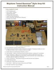
The banana plug plugged in<strong>to</strong> a multi meter. Note that some meters have different spacing and may<br />
not accept a dual banana plug. You can use individual banana plugs <strong>to</strong> do <strong>the</strong> same thing on wider<br />
spaced meters
<strong>How</strong> <strong>to</strong> <strong>assemble</strong> <strong>the</strong> Bias Current Checker<br />
Insert a 8 pin tube in<strong>to</strong> <strong>the</strong> 8 pin PC socket. This is done so that all <strong>the</strong> pins line up properly on <strong>the</strong><br />
tube socket. You may not be able <strong>to</strong> get a tube in<strong>to</strong> <strong>the</strong> socket later if you do not insert one now.<br />
Slide on <strong>the</strong> Ring now - If you forget <strong>to</strong> do this now, it will be <strong>to</strong>o late later. I like <strong>to</strong> super glue <strong>the</strong><br />
ring <strong>to</strong> <strong>the</strong> socket now, so it be<strong>com</strong>es part of <strong>the</strong> socket. The ring helps center <strong>the</strong> tube socket on<br />
<strong>the</strong> tube base and gives <strong>the</strong> tube socket a nice place <strong>to</strong> rest. Bend <strong>the</strong> tube socket pins so that <strong>the</strong>y<br />
are straight up, so <strong>the</strong>y will line up with <strong>the</strong> circuit board holes properly.<br />
The circuit board has small numbers for each pin. The 8 pin PC tube socket has numbers on it also.<br />
Line up <strong>the</strong> numbers so <strong>the</strong>y match and slide <strong>the</strong> circuit board on<strong>to</strong> <strong>the</strong> Tube socket pins. The key<br />
on your tube base and <strong>the</strong> key on your tube socket should be pointing between pin 8 and pin 1 on<br />
<strong>the</strong> PC board.
Check <strong>to</strong> make sure you put <strong>the</strong> ring on<br />
Solder all <strong>the</strong> tube socket pins <strong>to</strong> <strong>the</strong> PC board<br />
The holes in <strong>the</strong> circuit board are drilled for 20 gauge wire. Cut 7 pieces of 20 gauge wire about 2 <strong>to</strong><br />
3 inches long. See my tip below about wire lengths. Strip <strong>the</strong> insulation off <strong>the</strong> 20 gauge wire. Push<br />
<strong>the</strong> 20 gauge wires down in<strong>to</strong> <strong>the</strong> 7 holes as far as <strong>the</strong>y will go. There is nothing behind <strong>the</strong> board<br />
<strong>the</strong>y can short out on, so just push till <strong>the</strong> wire s<strong>to</strong>ps.<br />
The 20 gauge wires should stand up in <strong>the</strong> air by <strong>the</strong>mselves, which makes <strong>the</strong>m easier <strong>to</strong> solder.<br />
Solder <strong>the</strong> 7 wires in<strong>to</strong> <strong>the</strong> 7 holes on <strong>the</strong> circuit board. Pin 6 does not have a hole.<br />
The image fur<strong>the</strong>r down <strong>the</strong> page shows <strong>the</strong> wires standing up in <strong>the</strong> air<br />
I like <strong>to</strong> trim <strong>the</strong> 7 x 20 gauge wires so that each one is a bit shorter than <strong>the</strong> next one. This makes it<br />
much easier <strong>to</strong> slide <strong>the</strong> wires in<strong>to</strong> <strong>the</strong> tube base one at a time. This image is an exaggeration of <strong>the</strong><br />
wire lengths. Each wire is maybe about 1/8th inch shorter than <strong>the</strong> next
The bases already have a wire hole drilled in <strong>the</strong> proper place. This hole is right in front of pin 6. Pin<br />
6 is not used on most 8 pin power tubes and so this makes a great place for <strong>the</strong> wire <strong>to</strong> enter <strong>the</strong><br />
tube base. Slide <strong>the</strong> wire in<strong>to</strong> <strong>the</strong> hole in <strong>the</strong> base The image below shows what this looks like.<br />
Strip <strong>the</strong> wire ends and solder <strong>the</strong> Black/Red zip cord <strong>to</strong> <strong>the</strong> circuit board. It helps if <strong>the</strong> Red wire is<br />
cut just a tiny bit shorter than <strong>the</strong> black wire. The black wire is soldered <strong>to</strong> <strong>the</strong> pad where pin 8 is.<br />
The red wire is soldered <strong>to</strong> <strong>the</strong> pad next <strong>to</strong> pin 6.<br />
Make sure your solder connections are clean and that <strong>the</strong>re is no way a wire or solder blob can<br />
short out on<strong>to</strong> ano<strong>the</strong>r part of <strong>the</strong> circuit board. Make sure you do not use <strong>to</strong>o much solder and<br />
jumper across <strong>the</strong> circuit board sections.<br />
Tip: I like <strong>to</strong> bend <strong>the</strong> tip of <strong>the</strong> red wire at a 90 degree angle before I solder it.<br />
This keeps <strong>the</strong> red wire from getting <strong>to</strong>o close <strong>to</strong> pin 5
Push <strong>the</strong> two sections <strong>to</strong>ge<strong>the</strong>r slowly. This part can be a bit tricky so take your time. You have <strong>to</strong><br />
rotate <strong>the</strong> tube base and <strong>the</strong> tube socket circuit board assembly so that pin 6 lines up in a straight<br />
line. Move <strong>the</strong> two items closer <strong>to</strong>ge<strong>the</strong>r and align all 7 of <strong>the</strong> 20 gauge wires so <strong>the</strong>y go through <strong>the</strong><br />
holes on <strong>the</strong> tube base. See my wire length tip because it makes this part much easier.<br />
The technique is <strong>to</strong> pull a bit of <strong>the</strong> zip cord, pull everything closer, pull some more zip cord, pull<br />
everything closer, etc. It helps if you can guide <strong>the</strong> 7 wires in<strong>to</strong> <strong>the</strong> tube base holes with a small set<br />
of needle nose pliers or some sort of dental pick device. When you get it right, <strong>the</strong> 7 wire tips will be<br />
sticking out <strong>the</strong> bot<strong>to</strong>m of <strong>the</strong> tube base pins. Double check <strong>to</strong> make sure all 7 wires are in <strong>the</strong> correct<br />
holes in <strong>the</strong> tube base. After you have made sure <strong>the</strong> 7 wires are in <strong>the</strong> correct holes, push <strong>the</strong><br />
whole assembly <strong>to</strong>ge<strong>the</strong>r tight.<br />
Tip:<br />
Before you solder, now is <strong>the</strong> time <strong>to</strong> make sure you have everything <strong>assemble</strong>d correctly. You can<br />
use a multimeter set <strong>to</strong> continuity <strong>to</strong> check <strong>the</strong> red and black wire connections. My multimeter beeps<br />
and this is very handy. These two points should have continuity<br />
1 - The tip of <strong>the</strong> black wire and pin 8 on <strong>the</strong> tube base = continuity<br />
2 - The tip of <strong>the</strong> red wire and pin 8 on <strong>the</strong> tube socket = continuity<br />
Solder all 7 wires <strong>to</strong> <strong>the</strong> tube base pins. You solder <strong>the</strong> wires by <strong>to</strong>uching your hot soldering iron <strong>to</strong><br />
<strong>the</strong> junction of <strong>the</strong> base pin and <strong>the</strong> 20 gauge wire. As soon as <strong>the</strong> junction is hot enough, <strong>to</strong>uch<br />
your solder <strong>to</strong> <strong>the</strong> junction and it will follow <strong>the</strong> wire down in<strong>to</strong> <strong>the</strong> tube base pin. You do not apply<br />
<strong>the</strong> solder <strong>to</strong> <strong>the</strong> outside of <strong>the</strong> tube base pin. It’s a delicate operation and one that takes a bit of<br />
practice <strong>to</strong> get good at. Your soldering iron tip should be very pointy and very close <strong>to</strong> <strong>the</strong> tube base<br />
pin so that <strong>the</strong> pin gets just as hot as <strong>the</strong> wire does. The Solder will follow <strong>the</strong> heat, you do not have<br />
<strong>to</strong> stuff <strong>the</strong> solder in<strong>to</strong> <strong>the</strong> hole.
Tips:<br />
I grind my soldering tips on a bench <strong>to</strong>p sander <strong>to</strong> a fine point for this type of work. I take a piece of<br />
solder with me <strong>to</strong> <strong>the</strong> sander and my solder iron is already hot. I spin <strong>the</strong> tip on <strong>the</strong> sander <strong>to</strong> get a<br />
nice point. The tip is now copper colored so I quickly tin <strong>the</strong> tip with solder <strong>to</strong> get a nice clean, pointy<br />
tip.<br />
If you blob solder all over <strong>the</strong> outside of <strong>the</strong> tube base pin, you will not be able <strong>to</strong> push it in<strong>to</strong> a tube<br />
socket on your amp. You may even damage a tube socket by trying <strong>to</strong> force an oversized pin in<strong>to</strong> it.<br />
If you do blob a bit of solder on <strong>the</strong> pins, you can do this. Clean all <strong>the</strong> solder off <strong>the</strong> tip of your soldering<br />
iron with a damp cloth. Heat up <strong>the</strong> tube base pin and wipe <strong>the</strong> solder blobs off with a cloth<br />
while <strong>the</strong> solder is still hot. You can also use an exac<strong>to</strong> knife or razor blade <strong>to</strong> gently slice off <strong>the</strong><br />
solder. It is way better <strong>to</strong> do it right <strong>the</strong> first time and not have <strong>to</strong> clean up a mess later<br />
Snip off all <strong>the</strong> 20 gauge wires after you have soldered <strong>the</strong>m
Strip <strong>the</strong> ends of <strong>the</strong> black and red wires. Tin <strong>the</strong> wire ends with a bit of solder. Loosen both set<br />
screws on <strong>the</strong> banana plug. Push in <strong>the</strong> black and red wires. Tighten down <strong>the</strong> set screws. You can<br />
install <strong>the</strong> wires in<strong>to</strong> <strong>the</strong> banana plug any way you like. If you plug it in<strong>to</strong> your meter one way, you<br />
will be reading negative <strong>current</strong> flow. If you plug it in<strong>to</strong> your meter <strong>the</strong> o<strong>the</strong>r way, you will be reading<br />
positive <strong>current</strong> flow. If your meter only works one way, you will have <strong>to</strong> make a note which way <strong>to</strong><br />
plug it in<strong>to</strong> your meter.<br />
<strong>How</strong> <strong>to</strong> use <strong>the</strong> Bias Current Checker<br />
1. Plug your Bias Checker in<strong>to</strong> a tube socket on an amp.<br />
2. Plug your power tube in<strong>to</strong> <strong>the</strong> Bias Checker.<br />
3. Plug <strong>the</strong> banana plug in<strong>to</strong> your Multimeter.<br />
4. Make sure you plug <strong>the</strong> banana plug in<strong>to</strong> <strong>the</strong> two holes on your meter that are for DC <strong>current</strong><br />
measurement.<br />
5. Set your Multimeter <strong>to</strong> DC milliamps in <strong>the</strong> under 200ma range.<br />
6. Turn on <strong>the</strong> amp and let it warm up in standby mode, if it has a standby.<br />
7. Take <strong>the</strong> amp off standby, but be ready <strong>to</strong> quickly put <strong>the</strong> amp back on standby if <strong>the</strong> <strong>current</strong> is<br />
<strong>to</strong>o high.<br />
8. Turn <strong>the</strong> <strong>bias</strong> pot until you get somewhere around 35 milliamps of <strong>current</strong>.<br />
9. 35ma is a Generic <strong>bias</strong> setting, set your <strong>bias</strong> accordingly<br />
10. Put <strong>the</strong> amp back on standby<br />
11. Remove <strong>the</strong> <strong>bias</strong> checker and move it <strong>to</strong> <strong>the</strong> next tube.<br />
12. Put <strong>the</strong> first tube back in<strong>to</strong> <strong>the</strong> tube socket.<br />
13. Check <strong>the</strong> next power tube and split <strong>the</strong> difference if <strong>the</strong>y are off just a bit.<br />
14. You cannot check <strong>the</strong> <strong>bias</strong> properly unless all <strong>the</strong> power tubes are installed and running.<br />
15. Each power tube pulls a certain amount of <strong>current</strong> and this alters <strong>the</strong> overall voltage on <strong>the</strong> power<br />
supply.<br />
16. If you try and read <strong>the</strong> <strong>bias</strong> with some of <strong>the</strong> power tubes out of <strong>the</strong> amp, you will not get a proper<br />
<strong>current</strong> reading.<br />
Example of a <strong>bias</strong> reading<br />
If you have 38 ma on one tube and 34 ma on ano<strong>the</strong>r, <strong>the</strong>y are still close enough <strong>to</strong> be called a<br />
matched pair. If you are off more than 8 or 10ma, that is not a real good matched pair but <strong>the</strong> amp will<br />
work. I have seen some Fenders be way off and still sound awesome.<br />
Different <strong>current</strong> readings between each of <strong>the</strong> power tubes can be caused a couple different things.<br />
It could be <strong>the</strong> tubes <strong>the</strong>mselves or <strong>the</strong> parts connected <strong>to</strong> each tube socket can alter <strong>the</strong> <strong>current</strong><br />
readings. You must swap <strong>the</strong> tubes around and read <strong>the</strong>m in different sockets <strong>to</strong> figure out what is going<br />
on. If a tube reads differently in a different socket, <strong>the</strong>n you can assume it’s not <strong>the</strong> tube. Screen<br />
grid resis<strong>to</strong>rs can drift and cause altered <strong>current</strong> readings. The output transformer windings can also<br />
be <strong>the</strong> problem. The <strong>bias</strong> supply can be sending different negative voltage levels <strong>to</strong> each tube.
If your amp has fixed <strong>bias</strong> but it does not have a <strong>bias</strong> pot<br />
If you do not have a <strong>bias</strong> pot, you will have <strong>to</strong> figure out where <strong>the</strong> fixed resis<strong>to</strong>r is in <strong>the</strong> <strong>bias</strong> circuit<br />
that controls <strong>the</strong> negative <strong>bias</strong> voltage. It is a resis<strong>to</strong>r that will be able <strong>to</strong> read <strong>the</strong> negative <strong>bias</strong> voltage<br />
on one end and is connected <strong>to</strong> ground on <strong>the</strong> o<strong>the</strong>r end. You have <strong>to</strong> change <strong>the</strong> <strong>bias</strong> resis<strong>to</strong>r <strong>to</strong><br />
a larger value for less <strong>bias</strong> <strong>current</strong> (more <strong>bias</strong> voltage) and a smaller value for more <strong>bias</strong> <strong>current</strong> (less<br />
<strong>bias</strong> voltage). This page will not be able <strong>to</strong> cover all situations you may run in<strong>to</strong> on a <strong>bias</strong> circuit that<br />
may need <strong>to</strong> be modded. Please go <strong>to</strong> <strong>the</strong> <strong>Hoffman</strong> Amplifiers tube amp forum for help, <strong>the</strong> people on<br />
my forum are very knowledgeable.<br />
If your amp is cathode <strong>bias</strong>ed<br />
You don’t really need a <strong>bias</strong> checker, but you can use one if you want <strong>to</strong> get a more accurate picture<br />
of what is going on. You can measure <strong>the</strong> voltage across <strong>the</strong> cathode resis<strong>to</strong>r and do some math.<br />
Measure <strong>the</strong> voltage on <strong>the</strong> cathode resis<strong>to</strong>r where it connects <strong>to</strong> pin 8. Divide that figure by <strong>the</strong> value<br />
of <strong>the</strong> cathode resis<strong>to</strong>r. Both power tubes usually go through one resis<strong>to</strong>r, so you divide that figure in<br />
half <strong>to</strong> see each power tubes <strong>current</strong>.<br />
Example:<br />
Two 6V6’s in a Fender share a 470 ohm cathode resis<strong>to</strong>r<br />
You measure 22 volts DC on pin 8 of ei<strong>the</strong>r power tube.<br />
Divide 22 volts by 470 ohms = .0468 amps<br />
Divide that by 2 <strong>to</strong> get each power tubes <strong>current</strong> and you get .0234 amps<br />
Each power tube is flowing 23.4 milliamps of <strong>current</strong><br />
Of course, one power tube may be pulling 20 milliamps and one 26 milliamps.<br />
The <strong>bias</strong> checker can tell you more accurately what each tube is doing.<br />
Multiple <strong>bias</strong> checkers<br />
One <strong>bias</strong> checker for each power tube in your amp would be <strong>the</strong> ideal situation. Switching <strong>the</strong> amp<br />
on and off and moving <strong>the</strong> <strong>bias</strong> checker around is less than ideal. The problem with this is that you<br />
have <strong>to</strong> have some sort of switching situation that re-connects a tube after you switch <strong>to</strong> <strong>the</strong> next<br />
tube. I made such a thing years ago after finding a multiple push but<strong>to</strong>n switch that was able <strong>to</strong> switch<br />
properly. You could also have multiple meters running it’s own <strong>bias</strong> checker and read multiple tubes at<br />
<strong>the</strong> same time.