Q1) a) Draw the block diagram of a SMART TRANSMITTER with ...
Q1) a) Draw the block diagram of a SMART TRANSMITTER with ...
Q1) a) Draw the block diagram of a SMART TRANSMITTER with ...

You also want an ePaper? Increase the reach of your titles
YUMPU automatically turns print PDFs into web optimized ePapers that Google loves.
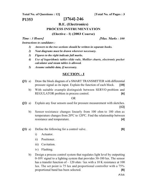
P1353<br />
Instructions to candidates :<br />
1) Answers to <strong>the</strong> two sections should be written in separate books.<br />
2) Neat <strong>diagram</strong>s must be drawn wherever necessary.<br />
3) Figures to <strong>the</strong> right indicate full marks.<br />
4) Use <strong>of</strong> logarithmic tables slide rule, Mollier charts, electronic pocket<br />
calculator and steam tables is allowed.<br />
5) Assume suitable data, if necessary.<br />
<strong>Q1</strong>) a) <strong>Draw</strong> <strong>the</strong> <strong>block</strong> <strong>diagram</strong> <strong>of</strong> a <strong>SMART</strong> <strong>TRANSMITTER</strong> <strong>with</strong> differential<br />
pressure signal as its input. Explain <strong>the</strong> function <strong>of</strong> each <strong>block</strong>. [10]<br />
b) With suitable example distinguish between SERVO problem and<br />
REGULATOR problem in process control. [6]<br />
OR<br />
Q2) a) Explain any four sensors used for pressure measurement <strong>with</strong> sketches.<br />
[12]<br />
b) Sensor resistance changes linearly from 100 ohm to 180 ohm as<br />
temperature changes from 20ºC to 120ºC. Find <strong>the</strong> relationship between<br />
resistance and temperature. [4]<br />
Q3) a) Define <strong>the</strong> following for a control valve. [8]<br />
i) Actuator.<br />
ii) Positioner.<br />
iii) Cavitation.<br />
iv) Flashing.<br />
b) Design a process control system that regulates light level by outputting<br />
0-10V signal to a lighting system that provides 30-180 lux. The sensor<br />
has a transfer function <strong>of</strong> – 120 ohm / lux <strong>with</strong> a 10 K resistance at 100<br />
lux. The set point is 75 lux and proportional controller <strong>with</strong> a 75%<br />
proportional band has been selected. [8]<br />
P.T.O.
OR<br />
Q4) a) Sketch a Digital Control valve and explain its working. Where it is used?<br />
[8]<br />
b) A temperature control system inputs <strong>the</strong> controlled variable as a range<br />
0-2V. Final control element is a heater control module which requires<br />
0-5V. Develop a PID controller for this application <strong>with</strong> K p = 2.4%/%,<br />
K I = 9% / min / % K D = 0.7% / % / min.<br />
The period <strong>of</strong> fastest expected change in process is estimated to be 8 sec.<br />
[8]<br />
Q5) a) Explain <strong>the</strong> term “Statistical Process Control”. Where it is applied? [6]<br />
b) With a <strong>block</strong> <strong>diagram</strong> explain “Model Reference Adaptive Controller”.[6]<br />
c) <strong>Draw</strong> <strong>the</strong> P & I Diagram <strong>of</strong> “Feed forward Control” <strong>of</strong> a Heat Exchanger.<br />
Write <strong>the</strong> specifications <strong>of</strong> <strong>the</strong> instruments used in it. [6]<br />
OR<br />
Q6) a) What is a “Self Tuning Controller”? Explain <strong>with</strong> a <strong>block</strong> <strong>diagram</strong>. [6]<br />
b) <strong>Draw</strong> <strong>the</strong> P & I Diagram for <strong>the</strong> cascade control scheme for a jacketed<br />
CSTR (Continuously Stirred Tank Reactor) write <strong>the</strong> specifications <strong>of</strong><br />
<strong>the</strong> instruments used in it. [6]<br />
c) With a <strong>block</strong> <strong>diagram</strong> explain “Programmed Adaptive Control”. [6]<br />
Q7) a) With a <strong>block</strong> <strong>diagram</strong> explain “Feedforward Optimizing Control”. [6]<br />
b) What are <strong>the</strong> different modelling approaches in Process Control?<br />
Compare among <strong>the</strong>m. [10]<br />
OR<br />
Q8) a) What is meant by “Constraint Handling”. Explain any one method for<br />
<strong>the</strong> same. [8]<br />
b) Explain <strong>the</strong> following terms: [8]<br />
i) Model Predictive Control (MPC).<br />
ii) Internal Model Control (IMC).<br />
[3764]-246 2
Q9) a) Distinguish between “Physical Ladder Diagram” and “Programmed<br />
Ladder Diagram”. [4]<br />
b) <strong>Draw</strong> <strong>the</strong> event sequence and ladder <strong>diagram</strong> for a PLC system for a<br />
“Bottle Filling Plant”. Consider all sensors as direct inputs to PLC.[12]<br />
OR<br />
<strong>Q1</strong>0)a) <strong>Draw</strong> <strong>the</strong> <strong>block</strong> <strong>diagram</strong> <strong>of</strong> a PLC and explain <strong>the</strong> function <strong>of</strong> each <strong>block</strong>.<br />
[6]<br />
b) Write <strong>the</strong> important specifications <strong>of</strong> a PLC having both Analog and<br />
Digital Inputs and outputs. [6]<br />
c) Define <strong>the</strong> following terms <strong>with</strong> respect to a PLC.<br />
i) I/O scan mode.<br />
ii) Execution mode. [4]<br />
<strong>Q1</strong>1)a) Develop a supervisory control flow chart <strong>of</strong> a system to increase <strong>the</strong> set<br />
point <strong>of</strong> a process reaction Vessel to a new value TSPNU. The temperature<br />
set point (TSP) is to be increased in steps <strong>of</strong> 0.2% <strong>with</strong> 5 sec delay<br />
between increases. If <strong>the</strong> pressure (P) rises above critical value (PCR),<br />
<strong>the</strong>n TSP should be decreased by 0.1% until P falls below PCR. Then<br />
<strong>the</strong> set point increases can begin again. [10]<br />
b) Explain <strong>the</strong> functions <strong>of</strong> <strong>the</strong> following in a Distributed Control System<br />
(DCS). [8]<br />
i) Local controller. ii) Co-ordinating controller.<br />
iii) Data Links. iv) Central Information Display.<br />
OR<br />
<strong>Q1</strong>2)Write short notes on (any three): [18]<br />
a) Flow Totaliser. b) Alarm Annunciator.<br />
c) Square root extractor. d) Classification <strong>of</strong> Control Panels.<br />
e) Digital Recorders.<br />
[3764]-246 3