user guide - night vision
user guide - night vision
user guide - night vision

Create successful ePaper yourself
Turn your PDF publications into a flip-book with our unique Google optimized e-Paper software.
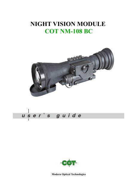
NIGHT VISION MODULE<br />
COT NM-108 BC<br />
Modern Optical Technologies
Safety Summary<br />
Before operating this product, carefully read and study this Operation and Maintenance Manual.<br />
The COT NM-108 BC <strong>night</strong> <strong>vision</strong> module is a precision electro-optical instrument and requires<br />
careful handling. To avoid physical danger or equipment damage when using the COT NM-108 BC,<br />
follow all WARNINGS, CAUTIONS and NOTES.<br />
Below you will find definitions of the alerts that appear throughout this Manual:<br />
WARNING — Identifies a clear danger to the person operating the equipment.<br />
CAUTION — Identifies risk of damage to the equipment.<br />
NOTE — Serves to highlight essential procedures, conditions, statements, or conveys important<br />
instructional data to the <strong>user</strong>.<br />
WARNINGS:<br />
• When installing the equipment on a weapon, be sure the weapon is clear and the safety is on<br />
before proceeding.<br />
• It is recommended that you use an eyecup on the eyepiece of the day scope, allowing for the<br />
eyepiece diameter and eye relief and having side paddle preferably in order to escape detection.<br />
• The light from the infrared illuminator is invisible to the unaided eye. However, the light can be<br />
detected by other <strong>night</strong> <strong>vision</strong> devices.<br />
CAUTIONS:<br />
• DO NOT dismantle the equipment.<br />
• Keep the equipment clean. Protect it from moisture, dramatic temperature changes, and electric<br />
shocks.<br />
DO NOT drop or hit the equipment.<br />
• Protect the equipment from overexposure to light: DO NOT activate the equipment in daylight<br />
with the objective lens cap removed; DO NOT aim the equipment at bright light sources (a fire,<br />
car headlights, lanterns, street lamps, room lights, etc.).<br />
• DO NOT force the equipment controls past their stopping points.<br />
• DO NOT leave the equipment activated during breaks in operation.<br />
• Verify that the equipment is off before installing a battery.<br />
• DO NOT store the equipment with the battery still in it.<br />
• To avoid deformation or damage, remove the light suppressor from the COT NM-108 BC<br />
before placing the equipment in storage.<br />
• Thoroughly clean and dry each item before placing them into the storage case.<br />
NOTES:<br />
• Optical axes of the COT NM-108 BC and day scope should align. It is not recommended for the<br />
distance between the axes to exceed 3 mm. If the difference in the axis heights of the COT NM-<br />
108 BC and day scope above the weapon rail exceeds 3 mm, you will need to replace the day<br />
scope mounting rings or monoblock.<br />
• At operating temperatures below -20 °C, alkaline battery life will be severely reduced. Under<br />
said conditions, the use of lithium battery is recommended.<br />
• The equipment requires some level of ambient light (moonlight, starlight, etc.) to function<br />
correctly.
• Performance of the device in <strong>night</strong>time conditions depends on the level of ambient light in the<br />
environment. Please remember the following:<br />
— The level of ambient light is reduced by the presence of clouds, shade, or objects that block<br />
natural light (trees, buildings, etc.).<br />
— The equipment is less effective when operated in shadows and other darkened areas.<br />
— The equipment is less effective when operated in rain, fog, sleet, snow, dust or smoke.<br />
— The equipment will not “see” through dense smoke.<br />
• For the purpose of returning defective components, retain all packaging materials.<br />
How to Use This Manual<br />
USAGE<br />
You must familiarize yourself with this entire manual before operating the equipment. Before<br />
performing any kind of maintenance on your COT NM-108 BC, read the section on maintenance in<br />
its entirety. Follow all WARNINGS, CAUTIONS, and NOTES.<br />
MANUAL OVERVIEW<br />
The Manual contains sections on operating and maintaining the COT NM-108 BC <strong>night</strong> <strong>vision</strong><br />
module.<br />
Throughout this Manual, COT NM-108 BC will be referred to as the NM-108 BC , “the device”, or<br />
“the equipment”.<br />
Reference data for the estimation of ambient illumination levels can be found in Appendix A.<br />
Chapter 1. INTRODUCTION<br />
1.1 General Information<br />
1.1.1 Type of Manual<br />
Operation and Maintenance (including a List of Spare Parts).<br />
1.1.2 Model Number and Equipment Name<br />
COT NM-108 BC<br />
1.1.3 Purpose of Equipment<br />
The COT NM-108 BC is a <strong>night</strong> <strong>vision</strong> system intended for use in conjunction with a daytime sight,<br />
or riflescope (hereafter referred to as a “day scope”). When mounted on a weapon in front of an existing<br />
day scope, the NM-108 BC adds to the scope’s capabilities a <strong>night</strong> <strong>vision</strong> function (up to range of<br />
900m), without affecting the boresight. Advisable day scope magnification values are 3 to 12X (4 to<br />
10X are optimal).<br />
The NM-108 BC is compatible with most commercial and military specification day scopes, and fits<br />
any Picatinny MIL STD 1913 or Weaver rail via the quick release mount.<br />
An optional long-range IR-illuminator enables use of the NM-108 BC in extremely low light conditions<br />
or total darkness. Other additional equipment, such as an infrared laser, red dot sight, etc., may
also be installed on the NM-108 BC top Weaver rail.<br />
NOTE:<br />
The NM-108 BC can also be installed in front of the viewfinders of various instruments to<br />
widen the operational illumination range.<br />
Chapter 2. DESCRIPTION AND DATA<br />
2.1 System Description<br />
The NM-108 BC consists of two primary parts, as shown in Figure 2-1: the <strong>night</strong> <strong>vision</strong> device<br />
(hereafter referred to as NVD), and the quick release mount system, or mount. The NM-108 BC is<br />
delivered already assembled: the mount (B) should be secured to the rail (A) of the NVD (D) with two<br />
screws.<br />
A<br />
B<br />
C<br />
D<br />
Figure 2-1. NM-108 BC NIGHT VISION CLIP ON SYSTEM<br />
The optical-electronic system of the NVD includes four main components: the objective and output<br />
lenses, an image intensifier tube, and the wired body (C).<br />
The objective lens focuses available light (photons) on the photocathode of the image intensifier tube<br />
(IIT). The light energy causes electrons to be released from the cathode. After being amplified, the<br />
electron flow represents an intensified version of the original image of the scene. The electrons then<br />
strike the IIT phosphor screen, which reacts to them by glow that is visible to the human eye. The image<br />
is projected by the output lens from the IIT screen to infinity, and the resulting image is magnified<br />
when viewed through the day scope. As such, when the NM-108 BC mounted in front of the day<br />
scope, it converts the latter into a <strong>night</strong> <strong>vision</strong> sight.<br />
The automatic brightness adjustment system maintains consistent image brightness, even in changing<br />
light conditions. The manual gain control (optional feature) allows the operator to refine the image<br />
contrast by compensating for overly bright or extremely dark conditions.<br />
The bright light protection system controls the existing ambient light through a photoreceiver, and
cuts off the IIT automatically when the illumination level exceeds the limit of 100…150 lx within 10<br />
seconds. The NM-108 BC turns back on when removed from the excessive light.<br />
The automatic shut-off function preserves battery life should the NM-108 BC be inadvertently activated.<br />
The NM-108 BC is powered by a single AA or CR123A battery.<br />
The NM-108 BC uses a LED indicator to show the operator when the bright light protection system is<br />
activated, or to indicate a low battery.<br />
The Picatinny / Weaver mount (B) has an adjustable lever-cam clamping device for easy, quick and<br />
reliable mounting and removal of the NM-108 BC.<br />
The NM-108 BC is shown in Figure 2-2. The ITEM NO. column in Table 2-1 indicates the number<br />
used to identify items in Figure 2-2.<br />
Figure 2-2. NM-108 BC NIGHT VISION CLIP ON SYSTEM
TABLE 2-1. SYSTEM DESCRIPTION<br />
ITEM DESCRIPTION ITEM DESCRIPTION<br />
1 Photoreceiver 9 Focus Knob<br />
2 Purge Screw 10 Nut<br />
3 Pivoted Shutter 11 Turn Switch<br />
4 Objective Lens Cap 12 Battery Cap with Adapter<br />
5 Gain Control Knob 13 Control Compartment<br />
6 Top Weaver Rail 14 Main Body<br />
7 Output Lens Cap 15 Cam Lever<br />
8 Double Lever-Lock Quick-Release<br />
Picatinny Mount<br />
16<br />
17<br />
Lever Holder<br />
Clamp<br />
2.2 Specifications<br />
TABLE 2-2. SYSTEM DATA<br />
Magnification<br />
Boresight Characteristics:<br />
— Accuracy<br />
— Retention<br />
— Repeatability<br />
ITEM<br />
DATA<br />
Unity (1X)<br />
Factory aligned to 0.75 MOA or better<br />
Permanent to within 1.5 MOA or better<br />
Within 0.75 MOA<br />
System Resolution subject to Image Intensifier Tube<br />
Resolution:<br />
— 45 to 54 lp/mm<br />
— 55 to 64 lp/mm<br />
— Over 65 lp/mm<br />
0.23 mrad/lp<br />
0.19 mrad/lp<br />
0.16 mrad/lp<br />
TABLE 2-3. MECHANICAL DATA<br />
ITEM<br />
DATA<br />
Dimensions (L×W×H)<br />
Weight (without Mount and Remote Control)<br />
Weight of Mount<br />
Height of the NM-108 BC Axis above Weapon’s<br />
Picatinny / Weaver Rail<br />
235×97×80 mm<br />
0.91 kg<br />
0.1 kg<br />
40 mm
TABLE 2-4. ELECTRICAL DATA<br />
Battery<br />
Cell Life at 20°C<br />
ITEM<br />
DATA<br />
Single AA (1.5V) or CR123A (3V)<br />
25 hr (1.5V) / 45 hr CR123A (3V)<br />
Interrupting Time*<br />
60 minutes<br />
* — Optional feature. Interrupting Time setting can be changed at the production stage, or the<br />
function can be completely disabled.<br />
TABLE 2-5. OPTICAL DATA<br />
Objective Lens Focal Length<br />
ITEM<br />
DATA<br />
108 mm<br />
Objective Lens F/number 1:1.5<br />
Focus Range<br />
Field of View<br />
Exit Pupil Diameter<br />
10 m to infinity<br />
9 o<br />
40 mm<br />
TABLE 2-6. ENVIRONMENTAL DATA<br />
ITEM<br />
DATA<br />
Operating Temperature<br />
Storage Temperature<br />
Illumination Required<br />
Immersion<br />
MIL-STD-810<br />
-40 to +50 о С<br />
-50 to +50 о С<br />
Natural <strong>night</strong> illumination (overcast<br />
starlight to moonlight)<br />
10 m for 30 minutes<br />
Complies
2.3 Standard Components<br />
The NM-108 BC standard components are shown in Figure 2-3 and listed in Table 2-7.<br />
The ITEM NO. column indicates the number used to identify items in Figure 2-3.<br />
TABLE 2-7. STANDARD COMPONENTS<br />
Figure 2-3. STANDARD COMPONENTS<br />
ITEM<br />
NO.<br />
DESCRIPTION<br />
1 NM-108 BC Night Vision Clip-On System - a <strong>night</strong> <strong>vision</strong> device equipped with<br />
quick release mount, to be installed on a Picatinny/ Weaver rail. Intended for use in<br />
conjunction with a day scope.<br />
2 Wireless Remote Control Unit – used to operate the NM-108 BC in short-time<br />
activation mode. Ensures quick and silent NM-108 BC activation / deactivation.<br />
Delivered with two CR2016 (3V) batteries installed.<br />
3 Light Suppressor - a rubber cup installed on the NM-108 BC output lens to reduce<br />
light scattering.<br />
4 Operation and Maintenance Manual - provides safety information, equipment<br />
description, mounting procedures, operating instructions, and preventive<br />
maintenance checks and services (including a List of Spare Parts).<br />
Q-TY<br />
1<br />
1<br />
1<br />
1
5 Special Wrench - an instrument used for repositioning the adapter in the NM-108<br />
BC battery cap, depending on the battery being installed.<br />
6 CR123А Battery - a single lithium battery used to power the NM-108 BC. 1<br />
7 Soft Case - used for carrying / storage of the NM-108 BC and its accessories. 1<br />
1<br />
2.4 Key Features<br />
• Converts your daytime scope, sight, or binoculars into a <strong>night</strong> <strong>vision</strong> ones<br />
• Mounts in front of any day scope with no re-zeroing required<br />
• Available in a variety of high performing Gen 2+ and Gen 3 image intensifier tube options<br />
• Wireless remote control<br />
• Both automatic and manual gain control<br />
• Powered by a single AA or CR123A battery<br />
• Bright light cut-off system<br />
• Bright light cut-off and low battery indications in the viewing area<br />
• Interrupting time 60 minutes (optional feature)<br />
• Filled with dry nitrogen to prevent internal fogging<br />
• Mounts on Picatinny / Weaver rail with a quick release mount<br />
• Mil Standard compliant<br />
2.5 System Limitations<br />
The NM-108 BC requires some ambient light (moonlight, starlight, etc.) to operate. Factors that can<br />
reduce natural <strong>night</strong> light and negatively affect the efficiency and operation of the NM-108 BC include:<br />
rain, fog, sleet, snow, and smoke; passing cloud cover and objects that produce shadows; and<br />
low-contrast environments such as snow-covered territory, sandy deserts, large bodies of water or<br />
grassy hills.<br />
Chapter 3. OPERATING INSTRUCTIONS<br />
3.1 Installation and Mounting<br />
CAUTION:<br />
To protect the image intensifier tube when the device is not in use or when it is being operated<br />
in daylight, keep the protective objective lens cap securely fitted over the lens.<br />
3.1.1 NM-108 BC Battery Installation<br />
NOTE:<br />
At operating temperatures below -20 °C , alkaline battery life will be severely reduced. Under<br />
said conditions, the use of lithium battery is recommended.<br />
CAUTION:<br />
Ensure that the device is off before installing a battery.<br />
Install the battery as follows (refer to Figure 3-1):<br />
1. Unscrew the battery cap (E) and check the position of the adapter (D). See Figure 3-2 for the correct<br />
positioning of the threaded adapter, which changes depending on the battery being installed.<br />
2. If necessary, change the adapter position in the cap. Use the special wrench.
3. Install the battery (C) into the battery compartment (B). Follow the battery symbol (A).<br />
4. Replace the battery cap (E).<br />
Figure 3-1. THE NM-108 BC. BATTERY INSTALLATION<br />
Figure 3-2. POSITIONS OF THE ADAPTER IN THE BATTERY CAP<br />
3.1.2 Installing the NM-108 BC on a Picatinny / Weaver Rail<br />
WARNING:<br />
When installing the equipment on a weapon, be sure the weapon is clear and the safety is on before<br />
proceeding.<br />
WARNING:<br />
It is recommended that you use an eyecup on the eyepiece of the day scope, allowing for the<br />
eyepiece diameter and eye relief and having side paddle preferably in order to escape detection.
NOTE:<br />
Optical axes of the NM-108 BC and day scope should align. It is not recommended for the distance<br />
between the axes to exceed 3 mm. If the difference in the axis heights of the NM-108 BC<br />
and day scope above the weapon rail exceeds 3 mm, you will need to replace the day scope<br />
mounting rings or monoblock.<br />
The NM-108 BC on Picatinny rail in front of a day scope is shown in Figure 3-3.<br />
Install the NM-108 BC on a Picatinny / Weaver rail in front of a day scope as follows:<br />
1. Remove the output lens cap and place it in the storage case.<br />
2. Remove the light suppressor from the storage case. Put it on the output lens in place of the cap.<br />
3. Unlock the clamping device of the NM-108 BC mount by pushing down on the dogs (A, see Figure<br />
3-4) and unlocking the levers (B).<br />
4. Install the NM-108 BC on the Picatinny / Weaver rail in front of the day scope so that the stops<br />
(A, Figure 3-5) slide into the transverse slots on the rail. The light suppressor should cover the day<br />
scope’s objective lens.<br />
5. Affix the NM-108 BC to the rail by locking the levers (B, Figure 3-4).<br />
6. Verify that the clamping device is firmly holding the NM-108 BC. If necessary, adjust the clamping<br />
device’s lever-cam locks as detailed in Part 3.1.4 (Clamping Device Adjustment).<br />
Figure 3-3. THE NM-108 BC INSTALLED ON A PICATINNY RAIL IN FRONT OF A DAY SCOPE<br />
Figure 3-4. MOUNT. TOP VIEW
3.1.3 Clamping Device Adjustment<br />
Figure 3-5. MOUNT. UNDERSIDE VIEW<br />
Adjust the mount clamping device as follows (refer to Figure 3-6):<br />
1. Remove the NM-108 BC from the weapon.<br />
2. With the clamping device unlocked (as shown in Figure 3-6), push the cam (B) towards the arrow,<br />
which will cause the nut (A) to slide out of its hollow.<br />
3. To tighten / loosen the clamping device, push down on the cam (B) and turn the nut (A) CW/ CCW<br />
respectively, in one-two increments (see note below). Much like when the cam (B) is released, backward-moving<br />
springs will cause the nut (A) to slide back into its hollow.<br />
NOTE:<br />
The eight-sided nuts of the mount lever-cam locks will only fit into their hollows only if<br />
turned in one of the discrete positions using increments equal to 360 o /8.<br />
4. Verify that the adjusted lever-cam lock is firmly holding the NM-108 BC.<br />
5. Repeat the procedure to adjust the clamping device’s second lever-cam lock.<br />
Figure 3-6. CLAMPING DEVICE ADJUSTMENT
3.1.4 Fastening Remote Control Unit to Weapon<br />
Using Velcro tape (A), fasten the wireless remote control unit (B) (Figure 3-7) to a weapon in an easily<br />
accessible place (e.g., on the front of the rifle stock) on the side of the NM-108 BC’s control compartment<br />
preferably.<br />
If the rifle has a Picatinny or Weaver rail on the forend you can use the Picatinny adapter for the wireless<br />
remote (C). Install adapter on the rail. Insert the wireless remote control unit in the adapter.<br />
Figure 3-7. REMOTE CONTROL UNIT<br />
3.2 Controls and Indicators<br />
CAUTION:<br />
DO NOT force the equipment controls past their stopping points.<br />
3.2.1 NM-108 BC Controls and Indicators<br />
The NM-108 BC controls are shown in Figure 3-8.<br />
The MN-108 BC controls and indicators are defined in Table 3-1. The ITEM NO. column indicates<br />
the number used to identify items in Figure 3-8.<br />
The NM-108 BC controls described elsewhere in this manual (levers and nuts of clamping device) are<br />
omitted in this Part.
Figure 3-8. NM-108 BC CONTROLS<br />
TABLE 3-1. NM-108 BC CONTROLS AND INDICATORS<br />
ITEM<br />
NO.<br />
CONTROL /<br />
INDICATOR<br />
FUNCTION<br />
1 Pivoted Shutter Closes / opens the photoreceiver when placed in the highest / lowest<br />
position.<br />
2 Gain Control Knob Adjusts the brightness of the image.<br />
3 Turn Switch Switches on the NM-108 BC, when turned CW from OFF to ON<br />
position.<br />
NOTE:<br />
Both ON and STB positions can only be entered if the switch is<br />
unlocked by pushing the spring-loaded stop (5) before turning.<br />
Switches the device to standby mode, when turned CCW from OFF to<br />
STB (see note above).<br />
Switches off the NM-108 BC, when turned CCW/ CW from ON/ STB<br />
to OFF.<br />
4 Focus Knob Focuses the objective lens. Adjusts for sharpest view of the scene. The<br />
total focus range is covered with 1.5 turn of the knob. Directions of<br />
focus (sharper to softer) are designated by a double arrow on the knob.<br />
5 Spring-loaded Stop<br />
Locks the turn switch in OFF position.<br />
- Remote Control<br />
Button<br />
- Built-in LED<br />
Indicator<br />
Activates/ deactivates the NM-108 BC in standby when pressed /<br />
released.<br />
PERMANENT RED GLOW in viewing area indicates excessive light<br />
conditions. After 10 seconds the image intensifier tube will be cut off.<br />
The NM-108 BC turns back again when moved away from the<br />
excessive light.<br />
FLASHING RED LIGHT in viewing area indicates a low battery. LED<br />
flashes three times every 3 minutes.
3.3 Operating Procedures<br />
3.3.1 Operating NM-108 BC<br />
Operating procedures should be performed in <strong>night</strong> light conditions only.<br />
CAUTION:<br />
USE OF THE CO-LR IN BRIGHTLY LIT CONDITIONS MAY DAMAGE THE IMAGE<br />
INTENSIFIER TUBE.<br />
CAUTION:<br />
PAY ATTENTION TO THE CAUTION NOTICE ON THE OBJECTIVE LENS CAP: “DO<br />
NOT REMOVE IN DAYLIGHT”.<br />
1. Verify that the battery is installed as required.<br />
2. Perform a visual estimation of the illumination level in the viewing area, using the reference data<br />
presented in Appendix A. You can begin operating the NM-108 BC if the illumination level is less<br />
than 1 lx.<br />
3. Remove the objective lens cap and place it over the lens’ housing.<br />
CAUTION:<br />
BEFORE REMOVING THE OBJECTIVE LENS CAP, VERIFY THAT THE<br />
PHOTORECEIVER IS OPEN.<br />
4. Verify that there are no bright light sources in the NM-108 BC field of view. Turn the device on.<br />
After a slight delay, a green glow will appear in the day scope’s output lens.<br />
CAUTION:<br />
AVOID EXPOSING THE DEVICE TO BRIGHT LIGHT SOURCES SUCH AS FIRELIGHT,<br />
HEADLIGHTS, SEARCHLIGHTS, ETC., AS THESE CAN DAMAGE THE NM-108 BC.<br />
5. To operate the NM-108 BC in short-time activation mode, turn the device on standby. To activate<br />
the NM-108 BC, press and hold the remote control button. Release the remote control button to<br />
deactivate the NM-108 BC.<br />
6. Observe the scene. Adjust the focus by rotating the NM-108 BC focus knob until the image<br />
becomes clear and sharp.<br />
7. Adjust the image contrast by rotating the NM-108 BC gain control knob.<br />
8. If the day scope includes a focusing ring (i.e., parallax adjustment knob), adjust the focus for a<br />
parallax free image.<br />
9. Turn on the day scope’s reticle illumination and adjust the reticle brightness.<br />
CAUTION:<br />
DO NOT LEAVE THE NM-108 BC ACTIVATED IF IT IS NOT BEING USED.<br />
NOTE:<br />
AUTOMATIC INTERRUPTING TIME IS 60 MINUTES. TO RESUME OPERATION, YOU<br />
WILL NEED TO RESTART THE NM-108 BC.
3.3.2 Operating in Changing Light Conditions<br />
If a mission must be carried out in changing light conditions, you can deactivate the bright light<br />
protection system of the NM-108 BC. To shut down the protection system, close the photoreceiver by<br />
flipping up the pivoted shutter.<br />
CAUTION:<br />
AFTER YOUR MISSION IS COMPLETE, OPEN THE PHOTORECEIVER BY FLIPPING<br />
THE PIVOTED SHUTTER DOWN.<br />
3.3.3 Shut-Down<br />
Shut-down the NM-108 BC as follows:<br />
1. Turn the device OFF. The green glow will disappear.<br />
2. Place the cap over the objective lens.<br />
3. Remove the NM-108 BC from the weapon.<br />
4. Remove the light suppressor from the output lens.<br />
5. Replace the cap on the output lens.<br />
6. Remove the batteries.<br />
CAUTION:<br />
DO NOT STORE THE EQUIPMENT WITH THE BATTERY STILL IN IT.<br />
CAUTION:<br />
REMOVE THE LIGHT SUPPRESSOR FROM THE NM-108 BC TO AVOID<br />
DEFORMATION OR DAMAGE.<br />
7. Ensure that the NM-108 BC and any accessories are clean and dry before placing them into<br />
the storage case.<br />
8. Place the NM-108 BC and any accessories into the storage case.<br />
9. Store the NM-108 BCand accessories in the appropriate locations in the case and close the<br />
cover.<br />
Chapter 4. PREVENTIVE MAINTENANCE AND TROUBLESHOOTING<br />
4.1 Preventive Maintenance Checks and Services (PMCS)<br />
Table 4-1: Preventive Maintenance Checks and Services, has been provided so that you can keep your<br />
equipment operable and in good condition.<br />
Perform all functional tests in the order listed in Table 4-1.<br />
Operating Procedures are detailed in Chapter 3.<br />
Always observe any CAUTIONS that appear in the table.<br />
Explanation of Table Entries:<br />
SEQ NO. column. Sequence numbers are for reference and appear in the order required to perform<br />
checks and services.<br />
LOCATION / ITEM TO CHECK / SERVICE column. Indicates the location and the item to be<br />
checked or serviced.<br />
PROCEDURE column. Details the checking / servicing procedure.<br />
NOT FULLY MISSION CAPABLE IF… column. Indicates what faults will prevent your<br />
equipment from operating successfully.
TABLE 4-1. PREVENTIVE MAINTENANCE CHECKS AND SERVICES<br />
SEQ.<br />
NO.<br />
ITEM TO<br />
CHECK<br />
CHECKING PROCEDURE<br />
BEFORE OPERATION CHECKS<br />
1 Completeness Inventory items by comparing them with the data<br />
specified in this manual.<br />
2 Body Inspect for cracks or damage. Scratches and<br />
gouges are OK if operation is not affected. Inspect<br />
for missing parts (purge screw, knobs).<br />
3 Objective Lens<br />
Cap<br />
Inspect for cuts, tears and dirt. Clean as required.<br />
4 Output Lens Cap Inspect for dirt or O-ring damage. Clean as required.<br />
5 Battery Compartment<br />
/ Cap with<br />
Adapter<br />
Check to make sure the adapter is present. Check<br />
for corrosion, cap damaged or retainer breaks.<br />
Check O-ring for cuts or damage.<br />
NOT FULLY<br />
MISSION<br />
CAPABLE IF:<br />
Items are missing.<br />
Cracked or damaged.<br />
Purge screw or knob<br />
is missing.<br />
Cap is torn or cut.<br />
Cap is not held up on<br />
the lens housing.<br />
Retainer is broken.<br />
Cap, O-ring or<br />
adapter is damaged or<br />
missing.<br />
6 Switch Check for operation (without battery). Switch is inoperative.<br />
7 Lenses Inspect for cleanliness, scratches, chips or cracks.<br />
Clean as required.<br />
8 Photoreceiver Inspect for cleanliness, scratches. Clean as required.<br />
9 Focus Knob Check to ensure there is free rotation through full<br />
range of travel (1.5 turn).<br />
10 Remote Control<br />
Unit<br />
Check for damage.<br />
Check Velcro tape for wear.<br />
11 Light Suppressor Inspect for cuts or tears. Check ease of installation<br />
and removal.<br />
12 Mount Inspect for damage or corrosion, and for missing<br />
parts. Check for proper operation.<br />
OPERATIONAL CHECKS<br />
Chipped or cracked.<br />
Scratches hinder <strong>vision</strong><br />
through the NM-<br />
108 BC.<br />
Photoreceiver is damaged.<br />
Knob is inoperative.<br />
Damaged. Unit or<br />
tape is missing.<br />
Light suppressor is<br />
torn or cut.<br />
Damaged. Some parts<br />
are missing. Clamping<br />
device is inoperative.<br />
CAUTION:<br />
The objective lens cap has an optical filter, which allows operational testing of the NM-108 BC<br />
in daylight. Activate the NM-108 BC in daylight with the objective lens cap on or in dark<br />
conditions.<br />
NOTE:<br />
Daylight checks are described below.
CAUTION:<br />
DO NOT forget to open the photoreceiver after finishing operational checks<br />
13 NM-108 BC<br />
Switch<br />
Insert the battery. Remove the output lens cap.<br />
Close the photoreceiver by flipping up the pivotal<br />
shutter. Turn the switch to ON position. Look for<br />
green glow (after a slight delay) in viewing area.<br />
Open the photoreceiver by flipping the pivotal<br />
shutter down. Look through the output lens and<br />
wait about 10 seconds for green glow to disappear.<br />
14 Remote Control Close the photoreceiver. Put the device in STB.<br />
Press and hold the remote control button. Look for<br />
the green glow in output lens. Release the button.<br />
Turn the device off.<br />
15 Focus Knob Turn the device on. Rotate the knob to ensure it<br />
adjusts for focus.<br />
16 Gain Control<br />
Knob<br />
Rotate the gain control knob to ensure it changes<br />
the screen brightness.<br />
17 Viewed Image Inspect for any operational defects (refer to Section<br />
4.3: Inspection Criteria for Proper Image Intensifier<br />
Tube Operation).<br />
AFTER CHECKING PROCEDURES<br />
No green glow.<br />
Green glow is<br />
present, yellow glow<br />
is absent.<br />
Green glow is absent.<br />
Knob does not adjust<br />
for focus.<br />
Knob does not adjust<br />
the screen brightness.<br />
Shading, edge glow,<br />
flashing, flickering,<br />
and intermittent<br />
operation, or excessive<br />
cosmetic defects<br />
are found.<br />
18 Turn off the NM-108 BC. Replace the protective cap on the NM-108 BC output lens.<br />
Remove the batteries. Return the NM-108 BC and all accessories to the storage case.<br />
4.2 Operator Troubleshooting<br />
The purpose of troubleshooting is to identify the most commonly occurring equipment malfunctions,<br />
their probable causes, and the corrective actions required to fix them.<br />
Table 4-2 lists the common malfunctions that may occur during the operation or maintenance of the<br />
NM-108 BC. Perform the tests, inspections, and corrective actions in the order listed in the table.<br />
This table cannot list all of the malfunctions that may occur with the NM-108 BC, or all of the<br />
tests and corrective actions that may be necessary. If you experience an equipment malfunction<br />
that is not listed, or is not fixed by the corrective actions listed in the table, please contact Armasight’s<br />
Customer Service center.
TABLE 4-2. OPERATOR TROUBLESSHOOTING<br />
MALFUNCTION<br />
Equipment fails to activate.<br />
Poor image quality.<br />
PROBABLE CAUSE / TEST/<br />
INSPECTION<br />
Battery is missing or improperly<br />
installed.<br />
Battery is dead.<br />
Battery surfaces or contacts are<br />
dirty or corroded.<br />
Remote control unit is damaged.<br />
Remote control batteries are<br />
dead.<br />
Defective image intensifier tube.<br />
Check focus.<br />
Objective and output lenses are<br />
dirty.<br />
Damaged optical components.<br />
LED indicator fails to activate. Visual inspection.<br />
The NM-108 BC affects boresight<br />
after installation or during<br />
the firing.<br />
Hindered rotation of the battery<br />
cap.<br />
Battery adapter difficult to remove.<br />
Light visible around light suppressor.<br />
Factory alignment is broken.<br />
Dirty cap thread.<br />
Damaged cap thread.<br />
Check for damaged adapter and<br />
battery cap.<br />
Incorrect position of the NM-108<br />
BC relative to the day scope.<br />
Check the light suppressor resilience.<br />
CORRECTIVE ACTION<br />
Insert battery or install it correctly.<br />
Replace battery.<br />
Clean the contact surfaces with a<br />
pencil eraser and / or alcohol and<br />
cotton swabs.<br />
Please contact Customer Support.<br />
Replace the batteries as per Part<br />
4.4.3.<br />
Please contact Customer Support.<br />
Refocus.<br />
Thoroughly clean the surface of<br />
each lens.<br />
Please contact Customer Support.<br />
Please contact Customer Support.<br />
Please contact Customer Support.<br />
Clean the thread.<br />
Please contact Customer Support.<br />
If damaged please contact Customer<br />
Support.<br />
Align the NM-108 BC position<br />
relative to the day scope.<br />
If light suppressor is defective<br />
please contact Customer Support.<br />
4.3 Inspection Criteria for Proper Image Intensifier Tube Operation<br />
4.3.1 Operational Defects<br />
Operational defects relate to the reliability of the intensifier, and are an indication of instability. If<br />
identified, the <strong>user</strong> will need to return the NM-108 BC immediately. Operational defects include<br />
shading, edge glow, flashing, flickering, and intermittent operation.<br />
A. Shading<br />
If shading is persistent, you will not be able to see a fully circular image (Figure 4-1). Shading is a<br />
very dark, high-contrast area with a distinct line of demarcation present, and you cannot see an image<br />
through it. Shading always begins on the edge and will eventually migrate inward until it spans across<br />
the entire image area. If you notice shading with your device, please contact Customer Support.
Figure 4-1. SHADING<br />
NOTE:<br />
VERIFY THAT ANY SHADING IS NOT THE RESULT OF IMPROPER EYE-RELIEF<br />
ADJUSTMENT.<br />
B. Edge Glow<br />
Edge glow is a bright area (it sometimes appears to be coloring) in the outer portion of the viewing<br />
area (see Figure 4-2). To check for edge glow, block out all light from the device by cupping a hand<br />
over the lens. If the image intensifier tube is displaying edge glow, the bright area will still show up; if<br />
edge glow occurs please contact Customer Support.<br />
Figure 4-2. EDGE GLOW<br />
C. Flashing, Flickering, or Intermittent Operation<br />
The image may appear to flicker or flash. If there is more than a single flicker, check for a loose battery<br />
adapter or a weak battery. If flickering continues, please contact Customer Support.<br />
4.3.2 Cosmetic Blemishes<br />
Cosmetic blemishes are usually the result of manufacturing imperfections. They do not affect the<br />
reliability of the image intensifier tube, and are not normally a cause for returning the NM-108 BC.<br />
However, some types of cosmetic blemishes can worsen over time and interfere with the <strong>user</strong>’s ability<br />
to properly operate the device during missions. If you believe a cosmetic blemish is cause for<br />
returning the device, record the specific nature of the problem on the maintenance forms and use the<br />
clock method to identify the position of the blemish and approximate distance from the center (e.g.,<br />
5:00 toward the outside, 2:30 near the center, or 1:00 midway).<br />
The following are examples of cosmetic blemishes:
A. Bright Spots<br />
A bright spot is a small, non-uniform bright area that may flicker or appear constant (Figure 4-3).<br />
Not all bright spots make the NM-108 BC returnable. Cup your hand over the lens to block out all<br />
light. If the bright spot remains, please contact Customer Support.<br />
Bright spots usually go away when all light is blocked out. Verify that any bright spots are not simply<br />
the result of bright light in the area you are observing. Bright spots are acceptable if they do not interfere<br />
with the <strong>user</strong>’s ability to view the scene or perform missions.<br />
Figure 4-3. EMISSION POINTS AND BRIGHT SPOTS<br />
B. Emission points<br />
Emission points are steady or fluctuating pinpoints of bright light in the image area that do not go<br />
away when all external light is blocked from the objective lens (Figure 4-3). The position of an emission<br />
point within the image area does not move. Not all emission points are cause to return the NM-<br />
108 BC. Verify that emission points are not simply light sources present in the scene you are observing.<br />
Emission points are acceptable if they do not interfere with the <strong>user</strong>’s ability to perform missions.<br />
C. Black Spots<br />
Black spots are cosmetic blemishes in the image intensifier or debris between the lenses. Black spots<br />
are acceptable as long as they do not interfere with the <strong>user</strong>’s ability to observe the scene. No action is<br />
required if this condition is present, unless the spots interfere with the operator’s ability to perform<br />
missions.<br />
D. Fixed-pattern Noise<br />
Fixed-pattern noise is usually a cosmetic blemish characterized by a faint hexagonal (honeycomb)<br />
pattern that appears throughout the viewing area. This typically occurs in excessively lit environments<br />
or when viewing very bright lights (See Figure 4-4). This pattern can be seen in every image intensifier<br />
if the level of light is high enough. This condition is acceptable as long as the pattern does not interfere<br />
with the <strong>user</strong>’s ability to view an image or their ability to perform missions.<br />
Figure 4-4.<br />
FIXED PATTERN NOISE
E. Chicken Wire<br />
Chicken Wire is an irregular pattern of dark thin lines that can appear in the field of view, either<br />
throughout the image area or in sections of the image area (See Figure 4-5). In the worst-case scenario,<br />
these lines will form hexagonal or square, wave-shaped lines. No action is required if this condition<br />
is present, unless it interferes with the <strong>user</strong>’s ability to view an image or their ability to perform<br />
missions.<br />
4.4 Maintenance<br />
4.4.1 General<br />
Figure 4-5. CHICKEN WIRE<br />
The NM-108 BC operator maintenance consists of operational tests, inspections for the unit serviceability,<br />
cleaning and mounting procedures, corrective actions (troubleshooting and replacement of a<br />
limited number of parts). Maintenance instructions covered elsewhere in this manual (PMCS, troubleshooting,<br />
etc.) are not repeated in this section.<br />
CAUTION:<br />
The NM-108 BC is a precision electro-optical instrument and must be handled carefully at all<br />
times to prevent damage.<br />
4.4.2 Cleaning Procedures<br />
CAUTION:<br />
Thoroughly dry each item before placing them into the storage case.<br />
Clean the NM-108 BC as follows:<br />
1. Gently brush off any dirt from the device’s body using a clean soft cloth.<br />
2. Moisten the cloth with fresh water and gently wipe external surfaces (except for glass surfaces).<br />
3. Dry any wet surfaces (except for glass surfaces) with another clean, soft, dry cloth.<br />
4. Using a lens brush, carefully remove all loose dirt from the glass surface.<br />
5. Slightly dampen a cotton swab with ethanol. Gently and slowly wipe the lenses (including the<br />
photoreceiver and the pivotal focusing lens). Without touching the lens holders, clean the glass surfaces<br />
in circular movements, beginning in the centre and moving out towards the edge. Change the<br />
cotton swab after each circular stroke. Repeat until the glass surfaces are clean.<br />
6. Clean the battery surfaces and contacts with a pencil eraser and/or alcohol-dampened cotton<br />
swabs.<br />
Clean optional equipment with a soft brush (cloth), soap, and water as required.
4.4.3 Battery Removal and Replacement<br />
Refer to Parts 3.1.1 for the NM-108 BC battery installation procedure, respectively.<br />
Replace the remote control batteries as follows:<br />
1. Using a screwdriver, unscrew the four screws (A, Figure 4-6) that affix the cover to the bottom of<br />
the unit. Remove the cover.<br />
2. Replace the batteries with two new ones (CR2016, 3V). Stack the batteries in its place under the<br />
leaf contact spring with the minus contacts directed towards the electric board, as the minus sign<br />
etched on the board indicates.<br />
3. Replace the cover and retighten the screws (A).<br />
Figure 4-6. REMOTE CONTROL UNIT. BATTERY INSTALLATION<br />
APPENDIX А<br />
(Reference)<br />
ESTIMATION OF AMBIENT ILLUMINATION LEVEL<br />
Table A-1 lists some common natural light conditions and their corresponding representative illumination<br />
values.<br />
TABLE А-1. STANDARD NATURAL LIGHT CONDITIONS AND ILLUMINATION<br />
VALUES<br />
Standard Natural Light Conditions<br />
Illumination Value, lx<br />
Quarter moon 0.05<br />
Full moon 0.30<br />
Late twilight sky 1.00<br />
Twilight sky 10.00<br />
Overcast sky in the daytime 500.00