Smartfire Installation Manual - Wilson Mohr
Smartfire Installation Manual - Wilson Mohr
Smartfire Installation Manual - Wilson Mohr

You also want an ePaper? Increase the reach of your titles
YUMPU automatically turns print PDFs into web optimized ePapers that Google loves.
SMARTFIRE Intelligent Combustion Control<br />
Page 7200-S-1<br />
General <strong>Installation</strong> Instructions<br />
Please read all installation and start-up<br />
instructions prior to working with the<br />
SMARTFIRE Intelligent Combustion Control<br />
System. A view port providing a clear view of<br />
the entire flame is strongly recommended.<br />
Do not discard packing material until all parts<br />
have been identified. Collect the five<br />
SMARTFIRE components required for controlling a<br />
burner (or zone of burners):<br />
1. Interface Panel (includes the Burner Brain, User<br />
Interface Terminal, and 24 VDC Power Supply)<br />
2. Air Valve Actuator<br />
3. Fuel Valve Actuator<br />
4. Air Flow Controller (comprised of a sensor probe<br />
and attached electronics in a flow body)<br />
5. Fuel Flow Controller (comprised of a sensor<br />
probe and attached electronics in a flow body)<br />
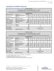
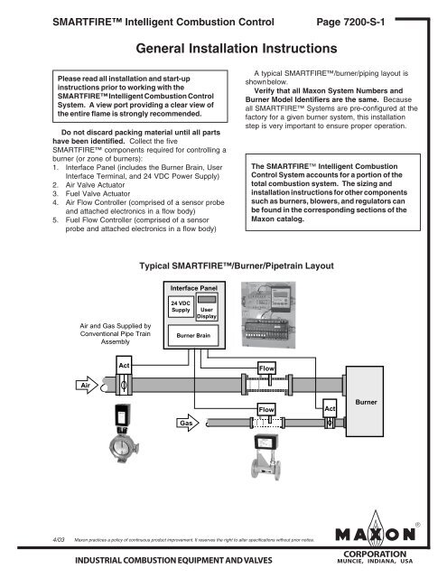
A typical SMARTFIRE/burner/piping layout is<br />
shown below.<br />
Verify that all Maxon System Numbers and<br />
Burner Model Identifiers are the same. Because<br />
all SMARTFIRE Systems are pre-configured at the<br />
factory for a given burner system, this installation<br />
step is very important to ensure proper operation.<br />
The SMARTFIRE Intelligent Combustion<br />
Control System accounts for a portion of the<br />
total combustion system. The sizing and<br />
installation instructions for other components<br />
such as burners, blowers, and regulators can<br />
be found in the corresponding sections of the<br />
Maxon catalog.<br />
Typical SMARTFIRE/Burner/Pipetrain Layout<br />
Interface Panel<br />
Air and Gas Supplied by<br />
Conventional Pipe Train<br />
Assembly<br />
24 VDC<br />
Supply<br />
User<br />
Display<br />
Burner Brain<br />
Act<br />
Flow<br />
Air<br />
Flow<br />
Act<br />
Burner<br />
Gas<br />
4/03<br />
Maxon practices a policy of continuous product improvement. It reserves the right to alter specifications without prior notice.<br />
INDUSTRIAL COMBUSTION EQUIPMENT AND VALVES<br />
mCORPORATION<br />
MUNCIE, INDIANA, USA
Page 7200-S-2<br />
SMARTFIRE Intelligent Combustion Control<br />
General <strong>Installation</strong> Instructions<br />
The SMARTFIRE System can be installed as a<br />
new or retrofit system. <strong>Installation</strong> is straightforward<br />
and can be accomplished in a working day for most<br />
applications. The major tasks involve installing the<br />
four field devices and mounting the SMARTFIRE<br />
Interface Panel. These tasks are described in the<br />
following sections:<br />
• Mechanical <strong>Installation</strong> Instructions<br />
(pages 7200-S-3 to 5)<br />
• Electrical <strong>Installation</strong> Instructions<br />
(pages 7200-S-6 to 15)<br />
The Interface Panel and the four field devices can<br />
be installed in any sequence.<br />
WARNING<br />
The SMARTFIRE System is not a safety<br />
device. The System provides cross-limited air/<br />
fuel ratio control and performs many redundant<br />
and physically diverse diagnostic tests<br />
during operation. However, in accordance with<br />
NFPA (National Fire Protection Agency) guidelines<br />
and other local and national safety codes,<br />
the User should provide appropriate safety<br />
equipment such as flame safeguard, high<br />
temperature limits, oxygen sensors, or redundant<br />
air and fuel flow sensors, as required.<br />
Before performing the installation steps described in<br />
these sections, please note the following general<br />
guidelines and safety instructions:<br />
• Validate the air and fuel flow measurements<br />
during commissioning by using the pressures at<br />
the burner.<br />
• The SMARTFIRE Interface Panel must be<br />
mounted in a protected enclosure.<br />
• Check for air and fuel leaks before the burner is<br />
started.<br />
• CAUTION: Never place hands or fingers in the<br />
Valve Actuators/Valve Assemblies.<br />
• If the piping requirements outlined in the Mechanical<br />
<strong>Installation</strong> Instructions (Page 7200-S-3)<br />
cannot be achieved within the User’s allocated<br />
space for the combustion system, call Maxon<br />
SMARTFIRE Support at 800-652-3553 (within<br />
the United States or Canada).<br />
• Eliminate any construction debris from the fuel<br />
and air pipetrains before installing the Flow<br />
Controllers to prevent blockages in the flow<br />
conditioning screens.<br />
• Verify that the combustion air blower is properly<br />
filtered. (Proper filtering ensures that the air<br />
sensing probe of the SMARTFIRE Flow<br />
Controller is not contaminated by particulate<br />
matter or water.)<br />
• Verify that the gas regulator is sized for both the<br />
maximum and minimum fuel flow required by the<br />
burner and/or application.<br />
After the installation steps are completed, follow the<br />
SMARTFIRE checkout and startup procedures<br />
provided in the Start-up and Operation Instructions<br />
(Page 7200-S-16 to 21).<br />
mCORPORATION<br />
MUNCIE, INDIANA, USA<br />
INDUSTRIAL COMBUSTION EQUIPMENT AND VALVES<br />
Maxon practices a policy of continuous product improvement. It reserves the right to alter specifications without prior notice.
SMARTFIRE Intelligent Combustion Control<br />
Page 7200-S-3<br />
Mechanical <strong>Installation</strong> Instructions<br />
Requirements<br />
When installing the SMARTFIRE Air and Fuel<br />
Flow Controllers and the Air and Fuel Valve Actuators,<br />
please note the following:<br />
• The arrow on the side of each Flow Controller<br />
should be oriented in the direction of flow.<br />
• The Flow Controllers and the Valve Actuators can<br />
be mounted in any orientation.<br />
• Refer to the Electrical <strong>Installation</strong> Instructions<br />
(pages 7200-S-6 to 7200-S-15) for cable and<br />
wiring requirements for each of the field devices.<br />
Maintain proper wire color code for 24 Volt DC<br />
Power and Data Communication Signals.<br />
In cases where replacement Flow Controller air<br />
and/or fuel sensor probes (with their attached electronics)<br />
need to be installed in their respective flow<br />
bodies, loosen the compression fitting sufficiently to<br />
insert the sensor probe and alignment pin into the<br />
flow body. The probe assembly should sit flush<br />
against the flow body’s horizontal mounting flange<br />
and should not be cocked at an angle. The compression<br />
fitting is then tightened.<br />
The following piping guidelines for the<br />
SMARTFIRE field devices ensure that the gas and<br />
air flow can be properly measured and controlled.<br />
Flow control accuracy is essential for optimum burner<br />
performance. If the piping requirements outlined<br />
in the Air Piping Guidelines and/or Gas Piping<br />
Guidelines cannot be achieved within the space<br />
allocated for the combustion system, call Maxon<br />
SMARTFIRE Support at 800-652-3553 (within<br />
the United States or Canada).<br />
Air Piping Guidelines<br />
Air piping between the combustion blower and the<br />
burner should be constructed using the following<br />
guidelines:<br />
• Locate the SMARTFIRE Air Valve Actuator at a<br />
maximum distance of 10 blower outlet diameters<br />
from the combustion blower. This configuration<br />
prevents blower pulsation (effects) created by the<br />
blower and air piping at low flow rates.<br />
• If Maxon is not supplying the blower, the User<br />
should contact the blower manufacturer for the<br />
maximum recommended distance (for a specific<br />
pipe diameter) between the blower outlet and a<br />
control valve (i.e., the SMARTFIRE Air Valve<br />
Actuator) to prevent Helmholtz effect.<br />
• The SMARTFIRE Air Flow Controller is installed<br />
downstream of the air valve actuator. It<br />
requires a total straight piping run of 14 flow body<br />
diameters (including approximately 4 diameters<br />
for the Flow Controller) to ensure accurate air<br />
flow control. See installation schematic on page<br />
7200-S-4:<br />
1. A minimum of seven (7) “straight” diameters are<br />
required upstream of the Air Flow Controller.<br />
Minimum length of pipe =<br />
7 x the air flow body diameter<br />
“Straight” diameter piping is defined as same<br />
diameter pipe with no elements such as valves,<br />
flanges, orifice plates, or bends within the specified<br />
pipe length.<br />
2. Exceed the above minimum requirement by as<br />
many straight diameters as space permits (i.e.,<br />
maximize the number of straight diameters<br />
upstream of the Air Flow Controller). This length<br />
ensures that the air stream can be properly<br />
conditioned and measured by the Air Flow<br />
Controller.<br />
3. A minimum of three (3) “straight” diameters are<br />
required downstream of the Air Flow Controller.<br />
Minimum length of pipe =<br />
3 x the air flow body diameter<br />
• Because the blower is rotational machinery,<br />
dampening pads for the blower stand and a<br />
flexible (bellows-type or braided stainless<br />
hose) connection from the blower discharge to<br />
the air piping are recommended.<br />
4/03<br />
Maxon practices a policy of continuous product improvement. It reserves the right to alter specifications without prior notice.<br />
INDUSTRIAL COMBUSTION EQUIPMENT AND VALVES<br />
mCORPORATION<br />
MUNCIE, INDIANA, USA
Page 7200-S-4<br />
SMARTFIRE Intelligent Combustion Control<br />
Mechanical <strong>Installation</strong> Instructions<br />
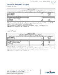
SMARTFIRE Air Piping Specification<br />
SMART FIRE<br />
Valve Assembly<br />
See Note 2<br />
A<br />
SMART<br />
FIRE Flow<br />
Controller Assembly<br />
See Note 1<br />
See Note 2<br />
Burner<br />
Blower<br />
From Gas Pipe Train<br />
C<br />
B D<br />
See Notes 3 & 4 See Note 4<br />
Note 1: For Maxon blowers, piping distance between the blower and the control valve must not exceed 10 times<br />
the blower outlet diameter. For non-Maxon blowers, contact the blower manufacturer for the maximum<br />
recommended length for the blower outlet size to prevent Helmholtz effects.<br />
Note 2: Piping diameters should match the Flow Controller’s ID<br />
Note 3: Maximize the straight length of Dimension C (space permitting)<br />
Note 4: Piping sections dimensioned C and D are customer-supplied<br />
Flow Controller and Pipetrain Dimensions<br />
Air Flow<br />
Controller<br />
Size<br />
Maxon<br />
Flow<br />
Controller<br />
P/N<br />
A<br />
Flow<br />
Controller<br />
OD/ID<br />
(inches)<br />
B<br />
Flow<br />
Controller<br />
Length<br />
(inches)<br />
Flow<br />
Controller<br />
Flange<br />
ID/OD<br />
(inches)<br />
Flow<br />
Controller<br />
Flange<br />
Bolt Circle<br />
(inches)<br />
Flange<br />
Hole<br />
Size<br />
Flow Controller<br />
Flange<br />
No. of Holes<br />
Equally Spaced<br />
C<br />
Minimum<br />
Length<br />
(inches)<br />
D<br />
Minimum<br />
Length<br />
(inches)<br />
8 SF SAC<br />
8.63/8.42<br />
34.0±.03<br />
8.12/10.62<br />
9.<br />
5 0.406<br />
8 59<br />
26<br />
12<br />
SF SAC<br />
12.75/12.54<br />
50.0±.05<br />
12.19/15.19<br />
13.81<br />
0.406<br />
12<br />
88<br />
38<br />
16<br />
SF SAC<br />
16.00/15.76<br />
64.0±.06<br />
16.25/19.75<br />
18.13<br />
0.406<br />
16<br />
111<br />
48<br />
20<br />
SF SAC<br />
20.00/19.76<br />
80.0±.08<br />
20.25/23.75<br />
22.13<br />
0.406<br />
20<br />
139<br />
60<br />
24<br />
SF SAC<br />
24.00/23.76<br />
96.0±.10<br />
24.25/27.75<br />
26.13<br />
0.562<br />
20<br />
167<br />
72<br />
28<br />
SF SAC<br />
28.00/27.77<br />
96.0±.10<br />
28.25/32.25<br />
30.<br />
5 0.625<br />
24<br />
195<br />
84<br />
Flange per Chicago Metal Rolled Products: (773-523-5757)<br />
mCORPORATION<br />
MUNCIE, INDIANA, USA<br />
INDUSTRIAL COMBUSTION EQUIPMENT AND VALVES<br />
Maxon practices a policy of continuous product improvement. It reserves the right to alter specifications without prior notice.
SMARTFIRE Intelligent Combustion Control<br />
Page 7200-S-5<br />
Mechanical <strong>Installation</strong> Instructions<br />
Gas Piping Guidelines<br />
Gas piping between the fuel train and burner<br />
should be constructed using the following guidelines:<br />
• Locate the SMARTFIRE Fuel Flow Controller<br />
downstream of the gas regulator and upstream of<br />
the gas valve actuator.<br />
• The SMARTFIRE Fuel Flow Controller requires<br />
a total straight piping run of 14 flow body diameters<br />
(including approximately 4 diameters for the<br />
Flow Controller) to ensure accurate fuel flow<br />
control. See installation schematic below:<br />
1. A minimum of five (5) “straight” diameters are<br />
required upstream of the Fuel Flow Controller.<br />
Minimum length of pipe =<br />
5 x the fuel flow body diameter<br />
“Straight” diameter piping is defined as same<br />
diameter pipe with no elements such as<br />
valves, flanges, orifice plates, or bends within<br />
the specified pipe length.<br />
2. Exceed the above minimum requirement by<br />
as many straight diameters as space permits<br />
(i.e., maximize the number of straight diameters<br />
upstream of the Fuel Flow Controller).<br />
This length ensures that the gas stream can<br />
be properly conditioned and measured by the<br />
Fuel Flow Controller.<br />
3. A minimum of five (5) “straight” diameters are<br />
required downstream of the Fuel Flow<br />
Controller.<br />
Minimum length of pipe =<br />
5 x the fuel flow body diameter<br />
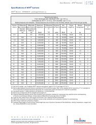
SMARTFIRE Gas Piping Specification<br />
Gas Line<br />
SMARTFIRE Flow<br />
Controller Assembly<br />
See Note 1<br />
A See Note 1<br />
To Burner<br />
SMARTFIRE<br />
Valve Assembly<br />
C<br />
See Notes 2 & 3<br />
B<br />
D<br />
D<br />
See Note 3<br />
Note 1: Piping diameters should match the Flow Controller’s ID<br />
Note 2: Maximize the straight length of Dimension C (space permitting)<br />
Note 3: Piping sections dimensioned C and D are customer-supplied<br />
Pipetrain Dimensions<br />
Flow<br />
Controller<br />
Size<br />
Oxy<br />
Flow<br />
Controller<br />
P/N<br />
2 SF SSOC<br />
3 SF SSOC<br />
4 SF SSOC<br />
6 SF SSOC<br />
Schedule 40 Pipe<br />
Fuel Flow<br />
Controller<br />
P/N<br />
A<br />
Flow<br />
Controller<br />
OD<br />
(inches)<br />
B<br />
Flow<br />
Controller<br />
Length<br />
(inches)<br />
C<br />
Minimum<br />
Length<br />
(inches)<br />
D<br />
Minimum<br />
Length<br />
(inches)<br />
ANSI Flange<br />
Rating<br />
(pounds)<br />
SF SNC<br />
2.38<br />
8 ± .02<br />
12<br />
12<br />
150<br />
SF SNC<br />
3.<br />
5 12<br />
± .02<br />
18<br />
18<br />
150<br />
SF SNC<br />
4.<br />
5 16<br />
± .02<br />
23<br />
23<br />
150<br />
SF SNC<br />
6.63<br />
24<br />
± .02<br />
32<br />
32<br />
150<br />
4/03<br />
Maxon practices a policy of continuous product improvement. It reserves the right to alter specifications without prior notice.<br />
INDUSTRIAL COMBUSTION EQUIPMENT AND VALVES<br />
mCORPORATION<br />
MUNCIE, INDIANA, USA
Page 7200-S-6<br />
SMARTFIRE Intelligent Combustion Control<br />
Electrical <strong>Installation</strong> Instructions<br />
System Wiring Requirements<br />
The following block diagram indicates the major<br />
sources and destinations of the electrical wiring<br />
required by the SMARTFIRE System. The System<br />
wiring is divided into the following four categories:<br />
• Burner management AC control wiring to/from<br />
the SMARTFIRE Burner Brain.<br />
• Current loop (4-20 mA) control and monitoring<br />
wiring from a User’s temperature controller and/<br />
or DCS system to the SMARTFIRE Burner<br />
Brain.<br />
• Network wiring from the SMARTFIRE Burner<br />
Brain to the SMARTFIRE Field Devices.<br />
• Power and network wiring between the<br />
SMARTFIRE Burner Brain and the 24VDC<br />
Power and the User Display. These connections<br />
are factory wired on the SMARTFIRE Interface<br />
Panel.<br />
A complete set of wiring schematics describing<br />
how SMARTFIRE is interfaced to a<br />
“typical” burner management system is<br />
shown in the following pages.<br />
SMARTFIRE Interface Panel<br />
User 4-20mA Inputs & Outputs<br />
FIRING RATE SOURCE<br />
AIR & GAS VALVE<br />
POSITION MONITORS<br />
BURNER START/STOP<br />
CONTROL SOURCE<br />
(120VAC RELAY<br />
COIL DRIVES)<br />
User Burner Management System<br />
BURNER START/STOP<br />
CONTROL MONITOR<br />
(120VAC SPST<br />
RELAY CONTACTS)<br />
J10<br />
J11<br />
J12<br />
s<br />
Relay Inputs Relay Outputs Relay Outputs<br />
BURNER BRAIN<br />
4-20 mA I/O J9<br />
RS232 J8<br />
24VDC J1<br />
Gas Flow J7<br />
Air Flow J6<br />
Gas Valve J5<br />
Air Valve J4<br />
Display J3<br />
Spare J2<br />
24VDC<br />
SUPPLY<br />
USER<br />
DISPLAY<br />
AIR & GAS FLOW<br />
RATE MONITORS<br />
GAS FLOW<br />
CONTROLLER<br />
GAS<br />
VALVE<br />
ACTUATOR<br />
AIR FLOW<br />
CONTROLLER<br />
AIR<br />
VALVE<br />
ACTUATOR<br />
SMARTFIRE Field Devices<br />
(Network Cabling)<br />
mCORPORATION<br />
MUNCIE, INDIANA, USA<br />
INDUSTRIAL COMBUSTION EQUIPMENT AND VALVES<br />
Maxon practices a policy of continuous product improvement. It reserves the right to alter specifications without prior notice.
SMARTFIRE Intelligent Combustion Control<br />
Page 7200-S-7<br />
Electrical <strong>Installation</strong> Instructions<br />
Typical SMARTFIRE Wiring Schematic<br />
120/1/60<br />
100<br />
1<br />
1<br />
Control Panel<br />
Power<br />
OFF ON<br />
SS100 3 4<br />
3<br />
10 AMP<br />
FU100<br />
4 4<br />
Control Panel<br />
Power On<br />
G<br />
X1 X2<br />
LT100<br />
2<br />
2<br />
101<br />
102<br />
5<br />
Combustion Air<br />
Pressure Switch<br />
CAP102<br />
Jumper all unused limits and interlocks<br />
6<br />
6<br />
Low Gas<br />
Pressure Switch<br />
LGP102<br />
7 7<br />
High Gas<br />
Pressure Switch<br />
HGP102<br />
8<br />
8<br />
Lockout Interlocks<br />
103<br />
104<br />
105<br />
106<br />
107<br />
108<br />
4<br />
4<br />
Customer<br />
Interlocks #1<br />
8<br />
Remote<br />
Burner Start<br />
7 4<br />
CR308<br />
9<br />
Customer<br />
Customer High Temperature<br />
Interlocks #2 Interlocks #3<br />
Limit SMARTFIRE Ready<br />
9 10 10<br />
11 2 312<br />
13<br />
J11-1 J11-2<br />
Honeywell<br />
HTL400<br />
See Line 307<br />
Flame Safeguard<br />
RM7800E-1010<br />
FSG106<br />
5<br />
4<br />
6<br />
Request for<br />
Heat<br />
4<br />
(L1)<br />
Lockout<br />
Interlocks<br />
7<br />
L2<br />
Neutral<br />
Interlocks<br />
Proven<br />
13 13<br />
2<br />
W<br />
X1 X2<br />
LT106<br />
2<br />
2<br />
Lockout Interlocks<br />
Indicates Interlocks<br />
Proven<br />
109<br />
4<br />
13<br />
110<br />
111<br />
4<br />
Field wiring shown for<br />
block and bleed valve<br />
arrangement<br />
7<br />
Main Valve<br />
VCS-1<br />
MV301<br />
8<br />
15<br />
12<br />
17<br />
17<br />
➤To Line 302<br />
(SMARTFIRE J10-2)<br />
Purging<br />
17 2<br />
A<br />
X1 X2<br />
LT109<br />
Indicates<br />
System Purging<br />
112<br />
113<br />
15 15<br />
Blocking Valve<br />
15 7 VCS-1 8<br />
BV303<br />
16<br />
20 Proof of<br />
Closure<br />
14<br />
18<br />
18<br />
➤To Line 302<br />
(SMARTFIRE J10-3)<br />
18<br />
Purge<br />
Complete<br />
2<br />
B<br />
X1 X2<br />
LT112<br />
Indicates<br />
Purge Complete<br />
114<br />
115<br />
116<br />
4<br />
15<br />
19<br />
19<br />
➤To Line 303<br />
(SMARTFIRE J10-5)<br />
Temperature Control<br />
Enabled<br />
19<br />
2<br />
G<br />
X1 X2<br />
LT115<br />
2<br />
Indicates Temperature<br />
Control Enabled<br />
TO: 200<br />
Continued on Line 200<br />
4/03<br />
Maxon practices a policy of continuous product improvement. It reserves the right to alter specifications without prior notice.<br />
INDUSTRIAL COMBUSTION EQUIPMENT AND VALVES<br />
mCORPORATION<br />
MUNCIE, INDIANA, USA
Page 7200-S-8<br />
SMARTFIRE Intelligent Combustion Control<br />
Electrical <strong>Installation</strong> Instructions<br />
Typical SMARTFIRE Wiring Schematic (Continued)<br />
Continued From Line 116<br />
Honeywell<br />
Flame Safeguard<br />
RM7800E1010<br />
FSG106<br />
2<br />
SMARTFIRE Enable Purge<br />
20 19<br />
High Fire<br />
3 23<br />
Alarm<br />
J11-3 J11-4<br />
Position<br />
See Line 308<br />
Jumper<br />
23<br />
23<br />
Remote Alarm<br />
Alarm<br />
2<br />
R<br />
X1 X2<br />
LT201<br />
2<br />
Indicates an Alarm<br />
Condition Exists<br />
SMARTFIRE Enable Ignition<br />
22 21<br />
J11-5 J11-6<br />
See Line 309<br />
Keyboard Display<br />
Module<br />
22<br />
1<br />
2 (DDL Cable)<br />
3<br />
4<br />
5<br />
This device is externally<br />
mounted to the<br />
nclosure door, and is<br />
ated for NEMA 4<br />
nvironment<br />
18<br />
5<br />
Low Fire<br />
Position<br />
Ignition 8<br />
(10 sec.)<br />
21<br />
Interrupted<br />
Pilot<br />
(15 sec.)<br />
F<br />
Flame Detector<br />
22<br />
Shutter<br />
G<br />
24<br />
25<br />
Blue<br />
White (S)<br />
Yellow<br />
White (L2)<br />
2<br />
XFMR203 SP204<br />
Ignition cable to the<br />
spark electrode must be<br />
run in separate conduit<br />
Pilot On<br />
25 26<br />
2<br />
X1<br />
B<br />
7 4<br />
X2<br />
LT205<br />
CR211<br />
25<br />
25 Pilot Valve 2<br />
PV206<br />
Wire to the detector should be #14AWG Type 600V<br />
insulated wire or equal. Wire must not be in the<br />
same conduit with power wiring.<br />
27<br />
28<br />
GND<br />
Spark Ignition<br />
Transformer<br />
Spark Plug<br />
Honeywell<br />
Self Checking<br />
Flame Detector<br />
C7061A-1012<br />
UVD208<br />
2<br />
2<br />
Spark Ignition<br />
Transformer<br />
Indicates<br />
Pilot is On<br />
Pilot Valve<br />
Flame Detector<br />
Main Valves 9<br />
29 29 2<br />
CR<br />
A B<br />
CR211<br />
Provides True Indication<br />
of Pilot Status<br />
205<br />
To enable shut-off valve power<br />
29 2<br />
mCORPORATION<br />
MUNCIE, INDIANA, USA<br />
INDUSTRIAL COMBUSTION EQUIPMENT AND VALVES<br />
Maxon practices a policy of continuous product improvement. It reserves the right to alter specifications without prior notice.
Split Ferrite, 1-turn<br />
Steward #28A2024-OA<br />
Flow Control Network<br />
SMARTFIRE Intelligent Combustion Control<br />
Page 7200-S-9<br />
Electrical <strong>Installation</strong> Instructions<br />
Typical SMARTFIRE Wiring Schematic (Continued)<br />
From line 215<br />
4<br />
2<br />
300<br />
301<br />
302<br />
303<br />
304<br />
305<br />
306<br />
307<br />
308<br />
309<br />
310<br />
311<br />
312<br />
313<br />
314<br />
315<br />
Blocking Valve<br />
From Line 112<br />
4<br />
VCS-2<br />
10<br />
12 32<br />
4<br />
4<br />
BV303<br />
Contacts close<br />
when valve<br />
starts open<br />
2<br />
2<br />
Alarm 1<br />
R<br />
X1 X2<br />
LT712<br />
Alarm 2<br />
R<br />
X1 X2<br />
LT713<br />
From Line 109<br />
From Line 115<br />
4<br />
SMARTFIRE<br />
Alarm Reset<br />
3 4<br />
PB705<br />
From Line 104<br />
To Line 104<br />
From Line 201<br />
To Line 201<br />
From Line 205<br />
34<br />
35<br />
To Line 204<br />
AIN0+ 1<br />
SMARTFIRE BURNER BRAIN<br />
AIN0-<br />
AIN1+<br />
AIN1-<br />
2<br />
3<br />
4<br />
2<br />
AOUT0+ 5<br />
1 Relay ret<br />
AOUT0- 6<br />
17<br />
AOUT1+ 7<br />
2 Drive to max air AOUT1- 8<br />
18<br />
AOUT2+ 9<br />
3 Drive to light off<br />
AOUT2- 10<br />
32<br />
AOUT3+ 11<br />
4 Main valve on<br />
AOUT3- 12<br />
19<br />
5 Modulation enable<br />
TX 1<br />
RX 2<br />
6 Select A<br />
CTS 3<br />
RTS 4<br />
7 Select B<br />
COM 5<br />
33<br />
8 Alarm Reset<br />
9 Spare Input<br />
+24VDC 1<br />
10 Spare Input<br />
GND 2<br />
+24VDC 1<br />
GND 2<br />
DATA A 3<br />
DATA B 4<br />
+24VDC 1<br />
12<br />
GND 2<br />
1 SMARTFIRE ready<br />
DATA A 3<br />
13<br />
DATA B 4<br />
2 SMARTFIRE ready ret<br />
+24VDC 1<br />
4<br />
3 Enable purge<br />
GND 2<br />
DATA A 3<br />
20<br />
4 Enable purge ret<br />
DATA B 4<br />
22<br />
+24VDC 1<br />
5 Enable ignition<br />
GND 2<br />
21<br />
DATA A 3<br />
6 Enable ignition ret<br />
DATA B 4<br />
7 Select A ack<br />
+24VDC 1<br />
GND 2<br />
8 Select A ack ret<br />
DATA A 3<br />
DATA B 4<br />
9 Select B ack<br />
+24VDC 1<br />
GND 2<br />
10 Select B ack ret<br />
DATA A 3<br />
DATA B 4<br />
4<br />
11 Alarm 1<br />
34<br />
4<br />
35<br />
12<br />
13<br />
14<br />
15<br />
16<br />
Alarm 1 ret<br />
Alarm 2<br />
Alarm 2 ret<br />
Spare output<br />
Spare output ret<br />
J10 (Input relay coils ref to relay ret)<br />
J11 (N.0. output relay contact pairs)<br />
J12 (N.0. output relay contact pairs)<br />
J9<br />
J8<br />
J1<br />
J7<br />
J5 J6<br />
J4<br />
J3<br />
J2<br />
SW1<br />
SW2<br />
CR3<br />
CR2<br />
CR1<br />
CR5<br />
CR4<br />
CR6<br />
Reserved for future SMARTFIRE use<br />
4/20 mA output, mass flow gas<br />
Reserved<br />
for future<br />
SMARTFIRE<br />
use<br />
Orange<br />
Weidmuller<br />
BLA 5.08<br />
Series Connector<br />
120VAC to<br />
24VDC Supply<br />
4/20 mA temperature control input<br />
4/20 mA output, mass flow air<br />
4/20 mA output, gas valve position<br />
4/20 mA output, air valve position<br />
24 VDC<br />
(+) (+) (-) (-)<br />
+24VDC<br />
GND<br />
DATA A<br />
DATA B<br />
SHLD<br />
L N PE<br />
120 VAC<br />
SMARTFIRE<br />
User Interface<br />
Data A<br />
Data B<br />
+24VDC<br />
GND<br />
DATA A<br />
DATA B<br />
SHLD<br />
+24VDC<br />
GND<br />
DATA A<br />
DATA B<br />
SHLD<br />
+24VDC<br />
GND<br />
DATA A<br />
DATA B<br />
SHLD<br />
+24VDC<br />
GND<br />
DATA A<br />
DATA B<br />
SHLD<br />
SMARTFIRE<br />
Gas Flow<br />
Controller<br />
SMARTFIRE<br />
Air Flow<br />
Controller<br />
SMARTFIRE<br />
Gas Valve<br />
Actuator<br />
SMARTFIRE<br />
Air Valve<br />
Actuator<br />
MAXON P/N 59829 cable<br />
used for connections to valve<br />
actuators and Flow Controllers.<br />
Apply color code:<br />
+24VDC, White/Orange<br />
GND, Orange<br />
Data A, White/Blue<br />
Data B, Blue<br />
RJ11<br />
Optional Telephone Gateway<br />
Maxon P/N 1055838<br />
2<br />
Split Ferrite,<br />
2-turns, line/neutral,<br />
Steward #28A2024-OA<br />
To Telephone<br />
Service<br />
2<br />
316<br />
2<br />
4<br />
Indicates terminals and wiring in Maxon<br />
Control Panel<br />
Indicates external wiring<br />
7/08<br />
Maxon practices a policy of continuous product improvement. It reserves the right to alter specifications without prior notice.<br />
INDUSTRIAL COMBUSTION EQUIPMENT AND VALVES<br />
mCORPORATION<br />
MUNCIE, INDIANA, USA
Page 7200-S-10<br />
SMARTFIRE Intelligent Combustion Control<br />
Electrical <strong>Installation</strong> Instructions<br />
Field Device Wiring Requirements<br />
A four-conductor cable with an outer shield is<br />
required between the SMARTFIRE Burner Brain and<br />
each of the four SMARTFIRE field devices (four field<br />
cables are required, one for each field device). A fifth<br />
cable of the same type is provided (pre-wired) with the<br />
Interface Panel. It connects the Burner Brain to the<br />
User Interface Terminal. An optional sixth cable can be<br />
run for connection to a remote display or to connect to<br />
a telephone gateway for remote monitoring by Maxon<br />
field support personnel.<br />
The recommended cable can be purchased from<br />
Maxon (P/N 59829) in a 500-foot spool, or it can be<br />
supplied in longer lengths (Connect-Air P/N W22P-1005)<br />
by contacting the following manufacturer.<br />
Connect-Air International, Inc.<br />
4240 “B” Street NW<br />
Auburn, Washington 98001<br />
Phone: 800-247-1978<br />
The shields of each field cable should be terminated<br />
just as the cable enters the enclosure that houses the<br />
Interface Panel. Shield wire length should not exceed<br />
2 inches.<br />
Maxon recommends all SMARTFIRE field device<br />
cables be routed through a dedicated conduit or at least<br />
one that carries only low voltage, instrumentation<br />
signals.<br />
Typically, flex conduit is used at each field device.<br />
The flex conduits feed a common steel conduit or cable<br />
tray that is run to the combustion panel. The<br />
SMARTFIRE control cable conduit(s) should not<br />
share the same conduit with any AC wiring or be in<br />
close proximity to the burner ignition cable. All wiring<br />
should be done in accordance with all applicable<br />
local and national electric codes.<br />
The maximum total length of the recommended<br />
Maxon cable (P/N 59829) must be:<br />
• Less than a total length of 1100 feet<br />
• No single cable run to a SMARTFIRE Flow<br />
Controller, remote User Display Terminal, or Digital<br />
Gateway greater than 300 feet<br />
• No single cable run to a SMARTFIRE Valve<br />
Actuator greater than 100 feet.<br />
If any single cable run to a SMARTFIRE Valve<br />
Actuator exceeds 100 feet in length but is less than<br />
300 feet, Belden Cable #3086A should be ordered.<br />
Belden product distribution information is available at<br />
1-800-BELDEN-1 or www.belden.com.<br />
If a single cable run to any SMARTFIRE device<br />
must exceed 300 feet, call the Maxon Product<br />
Support Team at 1-800-652-3553 within the United<br />
States or Canada.<br />
The Burner Brain diagram on the following page<br />
shows all input/output terminations to the User’s<br />
burner management system and field device cable<br />
terminations for the SMARTFIRE Valve Actuators<br />
and Flow Controllers. The tables on pages 7200-S-<br />
12 through 7200-S-15 explain the function of all<br />
inputs and outputs and network wiring color code.<br />
It is the responsibility of the User to ensure<br />
that Maxon’s SMARTFIRE Burner Brain is<br />
wired correctly to the proper burner start-up<br />
sequencing logic and combustion safety interlocks<br />
as required by local and national safety<br />
codes.<br />
The User’s burner management system and<br />
all related electrical control drawings that<br />
incorporate Maxon’s SMARTFIRE Combustion<br />
Control System should be reviewed by qualified<br />
personnel knowledgeable in all relevant safety<br />
and industrial combustion requirements.<br />
Maintain the integrity of the MAXON enclosure<br />
by using NEMA 4X or IP66 rated dust- and watertight<br />
electrical connectors. Use cable-sealing grips<br />
and strain-relief loops for any cord or cable. Use<br />
internal sealing materials on all conduit connections.<br />
Moisture can have a harmful effect on<br />
device internals if permitted to enter through wiring<br />
connectors. Ensure that the device connection is<br />
not at a low point of the conduit to avoid condensation<br />
run-off into the housing; install a drip loop if<br />
necessary. Make sure that the access cover plate<br />
is in place and securely fastened. All cover screws<br />
should be tightened using an alternate crosscorner<br />
tightening pattern. Cover screws should be<br />
checked periodically to ensure adequate sealing<br />
protection.<br />
mCORPORATION<br />
MUNCIE, INDIANA, USA<br />
INDUSTRIAL COMBUSTION EQUIPMENT AND VALVES<br />
Maxon practices a policy of continuous product improvement. It reserves the right to alter specifications without prior notice.
SMARTFIRE Intelligent Combustion Control<br />
Page 7200-S-11<br />
Electrical <strong>Installation</strong> Instructions<br />
Burner Brain Interconnect Diagram<br />
RELAY RET 1<br />
DRIVE TO MAX AIR 2<br />
DRIVE TO LIGHTOFF 3<br />
MAIN VALVE ON 4<br />
MODULATION ENABLE 5<br />
SELECT A 6<br />
SELECT B 7<br />
ALARM RESET 8<br />
SPARE INPUT 9<br />
N/C 10<br />
SMARTFIRE READY 1<br />
SMARTFIRE READY RET 2<br />
ENABLE PURGE 3<br />
ENABLE PURGE RET 4<br />
ENABLE IGNITION 5<br />
ENABLE IGNITION RET 6<br />
SELECT A ACK 7<br />
SELECT A ACK RET 8<br />
SELECT B ACK 9<br />
SELECT B ACK RET 10<br />
ALARM 1 11<br />
ALARM 1 RET 12<br />
ALARM 2 13<br />
ALARM 2 RET 14<br />
SPARE OUTPUT 15<br />
J10<br />
J11<br />
J12<br />
Relay Inputs Relay Outputs Relay Outputs<br />
BURNER BRAIN<br />
4-20 mA ma I/O J9<br />
RS232 J8<br />
24VDC J1<br />
Gas Flow J7<br />
Air Flow J6<br />
Gas Valve J5<br />
Air Valve J4<br />
Display J3<br />
Spare J2<br />
1<br />
2<br />
3<br />
4<br />
5<br />
6<br />
7<br />
8<br />
9<br />
10<br />
11<br />
12<br />
1<br />
2<br />
3<br />
4<br />
5<br />
1<br />
2<br />
1<br />
2<br />
3<br />
4<br />
1<br />
2<br />
3<br />
4<br />
1<br />
2<br />
3<br />
4<br />
1<br />
2<br />
3<br />
4<br />
1<br />
2<br />
3<br />
4<br />
1<br />
2<br />
3<br />
4<br />
AIN0 +<br />
AIN0 –<br />
AIN1 +<br />
AIN1 –<br />
AOUT0 +<br />
AOUT0 –<br />
AOUT1 +<br />
AOUT1 –<br />
AOUT2 +<br />
AOUT2 –<br />
AOUT3 +<br />
AOUT3 –<br />
TX<br />
RX<br />
CTS<br />
RTS<br />
COM<br />
+24VDC<br />
GND<br />
+24VDC<br />
GND<br />
DATA A<br />
DATA B<br />
+24VDC<br />
GND<br />
DATA A<br />
DATA B<br />
+24VDC<br />
GND<br />
DATA A<br />
DATA B<br />
+24VDC<br />
GND<br />
DATA A<br />
DATA B<br />
+24VDC<br />
GND<br />
DATA A<br />
DATA B<br />
+24VDC<br />
GND<br />
DATA A<br />
DATA B<br />
SPARE OUTPUT RET<br />
16<br />
4/03<br />
Maxon practices a policy of continuous product improvement. It reserves the right to alter specifications without prior notice.<br />
INDUSTRIAL COMBUSTION EQUIPMENT AND VALVES<br />
mCORPORATION<br />
MUNCIE, INDIANA, USA
Page 7200-S-12<br />
SMARTFIRE Intelligent Combustion Control<br />
Electrical <strong>Installation</strong> Instructions<br />
SMARTFIRE Input/Output Signal Descriptions<br />
Relay Inputs (120 VAC)<br />
Signal<br />
Name<br />
Terminal<br />
Signal Function<br />
Commands SMARTFIRE to<br />
checks air flow.<br />
open its air valve to a full open position and<br />
Commands SMARTFIRE to position its fuel valve at 5<br />
controlling air flow to the required starting flow setpoint.<br />
degrees and begins<br />
RELAY RET<br />
J 10-1<br />
Return for all 120VAC SMARTFIRE relay inputs.<br />
DRIVE TO MAX AIR<br />
J10-2<br />
DRIVE TO LIGHTOFF<br />
J10-3<br />
MAIN VALVE ON<br />
J 10-4<br />
Informs SMARTFIRE that the fuel shut-off valves have begun to open.<br />
Air/fuel ratio control is then enabled at the required starting firing rate.<br />
MODULATION ENABLE J10-5<br />
SELECT A<br />
J10-6<br />
Enables SMARTFIRE modulation<br />
rate input (J9-1, J9-2)<br />
of firing rate based on the 4-20mA firing<br />
Selects one of three SMARTFIRE air/fuel ratio curves installed in the Burner<br />
Brain or disables SMARTFIRE control. These selections are made as follows:<br />
- Default Operating Air/Fuel Ratio Curve is selected with no voltage applied to<br />
either input.<br />
- Curve No. 1<br />
- Curve No. 2<br />
SELECT B<br />
J10-7<br />
ALARM RESET<br />
J10-8<br />
SPARE INPUT<br />
J 10-9<br />
Reserved for future use.<br />
NO CONNECTION<br />
J 10-10<br />
No connection.<br />
is selected with Select A at 120 VAC and Select B at 0 VAC.<br />
is selected with Select A at 0 VAC and Select B at 120 VAC.<br />
- SMARTFIRE control disable is selected with 120 VAC on both inputs.<br />
The control disable function would be used during an on-line air/propane switch.<br />
This operational command is invalid during start-up.<br />
Resets all shutdown conditions, latched-air and fuel-limit alarms, and<br />
fuel flow check alarms. This reset function is performed when the<br />
SMARTFIRE Burner Brain senses a transition from 0 to 120 VAC.<br />
air and<br />
mCORPORATION<br />
MUNCIE, INDIANA, USA<br />
INDUSTRIAL COMBUSTION EQUIPMENT AND VALVES<br />
Maxon practices a policy of continuous product improvement. It reserves the right to alter specifications without prior notice.
SMARTFIRE Intelligent Combustion Control<br />
Page 7200-S-13<br />
Electrical <strong>Installation</strong> Instructions<br />
SMARTFIRE Input/Output Signal Descriptions<br />
Relay Outputs (120 VAC)<br />
Signal<br />
SMARTFIRE<br />
TM<br />
Name<br />
Terminal<br />
READY<br />
11-1<br />
Signal Function<br />
J Closed output contact indicates at start-up the following conditions are satisfied:<br />
M<br />
- All SMARTFIRE<br />
T components are functioning properly .<br />
- Control valves are in their standby position.<br />
M<br />
- SMARTFIRE System is ready to accept a "drive-to-maximum" air command<br />
T .<br />
SMARTFIRE<br />
TM<br />
READY RET<br />
J11-2<br />
ENABLE PURGE<br />
J11-3<br />
ENABLE PURGE RET<br />
J11-4<br />
ENABLE IGNITION<br />
J11-5<br />
ENABLE IGNITION RET J11-6<br />
SELECT "A" ACK<br />
J11-7<br />
SELECT "A" ACK RET J11-8<br />
SELECT "B" ACK<br />
J12-9<br />
SELECT "B" ACK RET J12-10<br />
ALARM 1<br />
J12-11<br />
ALARM 1 RET<br />
J12-12<br />
ALARM 2<br />
J12-13<br />
ALARM 2 RET<br />
J12-14<br />
SPARE OUTPUT<br />
J12-15<br />
SPARE OUTPUT RET<br />
J12-16<br />
After the pilot is lit and the main gas valve is opened by the burner management<br />
system, this output contact remains closed unless a shutdown condition or<br />
failure is detected.<br />
User-provided burner management hardware must employ the<br />
TM<br />
" SMARTFIRE Ready" output contacts as a start-up and running<br />
permissive.<br />
TM<br />
Output<br />
contact closes during the start-up sequence after the SMARTFIRE<br />
air<br />
valve reaches the full open position and air flow greater than 50 percent of the<br />
maximum flow required at high fire is measured by the air Mass Flow Controller.<br />
TM<br />
Contacts<br />
remain closed until SMARTFIRE detects an unsafe condition or until<br />
the burner is shutdown externally by the burner management system or User.<br />
M<br />
Closed<br />
output contact indicates when SMARTFIRE<br />
T is in a "low-fire start "<br />
condition. The contacts close during the start-up sequence after the following<br />
conditions are achieved:<br />
- Starting air flow has been accomplished<br />
- Fuel control valve is in its starting position (5 degrees is default)<br />
- Gas flow in excess of 1/20th of the flow required for high fire is not present<br />
(i.e., no appreciable fuel leak exists).<br />
TM<br />
Contact<br />
remains closed until SMARTFIRE detects an unsafe condition or until<br />
the burner is externally shutdown by the User or burner management system.<br />
Close/open output contact combinations acknowledge which air/fuel ratio curve<br />
TM<br />
is<br />
selected or if SMARTFIRE control has been disabled. Refer to Select A and<br />
Select B inputs for contact combinations.<br />
TM<br />
Closed<br />
output contact indicates that the SMARTFIRE<br />
System detected a flow<br />
test alarm condition, shutdown, or device failure. Refer to "Command and<br />
Display" Function for a list of all alarm conditions.<br />
Closed output contact indicates a lower level alarm condition that should be<br />
investigated to ensure proper system operation. Refer to "Command and<br />
Display" Functions for a list of all alarm conditions.<br />
Reserved<br />
for future SMARTFIRE<br />
T M<br />
use.<br />
4/03<br />
Maxon practices a policy of continuous product improvement. It reserves the right to alter specifications without prior notice.<br />
INDUSTRIAL COMBUSTION EQUIPMENT AND VALVES<br />
mCORPORATION<br />
MUNCIE, INDIANA, USA
Page 7200-S-14<br />
SMARTFIRE Intelligent Combustion Control<br />
Electrical <strong>Installation</strong> Instructions<br />
4 to 20 mA Inputs/Outputs<br />
Signal<br />
Name<br />
Terminal<br />
AIN 0+ (FIRING RATE)<br />
J9-1<br />
A 4 to 20<br />
follows:<br />
INPUTS<br />
Signal Function<br />
mA input signal that establishes the burner's firing rate setpoint is as<br />
- A 20 mA, full-scale signal represents a setpoint of 100 percent of the burner's<br />
maximum rated heat capacity.<br />
- A 4 mA signal represents the burner's minimum heat capacity.<br />
The User's temperature controller typically provides the firing rate signal.<br />
AOUT 0+ (GAS FLOW)<br />
J9-5<br />
AIN 0- (FIRING RATE)<br />
J9-2<br />
AIN 1+ (FUTURE USE)<br />
J9-3<br />
AIN 1- (FUTURE USE)<br />
J9-4<br />
AOUT 0- (GAS FLOW)<br />
J9-6<br />
AOUT 1+ (AIR FLOW)<br />
J9-7<br />
AOUT 1- (AIR FLOW)<br />
J9-8<br />
AOUT 2+<br />
(GAS VALVE POSITION)<br />
J9-9<br />
Reserved for future use.<br />
OUTPUTS<br />
The 4 to 20 mA output signals indicate the gas and air<br />
M<br />
the<br />
SMARTFIRE<br />
T Flow Controllers. For each signal :<br />
mass flow measured by<br />
- 20 mA represents the full-scale flow of the respective Flow Controller.<br />
- 4 mA represents no flow.<br />
Both<br />
outputs are isolated from the SMARTFIRE<br />
current.<br />
TM<br />
+ 24 VDC supply and sources<br />
The 4 to 20 mA output signals indicate the gas and air valve positions<br />
M<br />
measured<br />
by the SMARTFIRE<br />
T Valve Actuators. For each signal :<br />
as<br />
AOUT 2-<br />
(GAS VALVE POSITION)<br />
AOUT 3+<br />
(AIR VALVE POSITION)<br />
AOUT 3-<br />
(AIR VALVE POSITION)<br />
J9-10<br />
J9-11<br />
J9-12<br />
- 20 mA indicates a valve position of 100 degrees.<br />
- 4 mA indicates a valve position of 0 degrees.<br />
The Valve Actuators currently open to a maximum position of 80 degrees. Each<br />
TM<br />
signal<br />
is isolated from the SMARTFIRE System's + 24 VDC supply and<br />
sources current.<br />
RS-232 Interface<br />
Signal<br />
Name Terminal<br />
TX<br />
J8-1<br />
RX<br />
J8-2<br />
CTS<br />
J8-3<br />
RTS<br />
J8-4<br />
COM<br />
J8-5<br />
Signal Function<br />
Reserved<br />
for future RS-232 SMARTFIRE<br />
diagnostic purposes.<br />
TM<br />
monitoring, configuration, and<br />
mCORPORATION<br />
MUNCIE, INDIANA, USA<br />
INDUSTRIAL COMBUSTION EQUIPMENT AND VALVES<br />
Maxon practices a policy of continuous product improvement. It reserves the right to alter specifications without prior notice.
SMARTFIRE Intelligent Combustion Control<br />
Page 7200-S-15<br />
Electrical <strong>Installation</strong> Instructions<br />
Power and Field Device Cable Terminations<br />
Signal<br />
Name<br />
INPUT POWER<br />
Terminal<br />
+ 24 VDC<br />
J1-1<br />
GAS FLOW CONTROLLER<br />
GND<br />
J1-2<br />
+ 24 VDC<br />
J7-1<br />
GND<br />
J7-2<br />
DATA A<br />
J7-3<br />
AIR FLOW CONTROLLER<br />
DATA B<br />
J7-4<br />
+ 24 VDC<br />
J6-1<br />
GND<br />
J6-2<br />
DATA A<br />
J6-3<br />
GAS VALVE ACTUATOR<br />
DATA B<br />
J6-4<br />
+ 24 VDC<br />
J5-1<br />
GND<br />
J5-2<br />
DATA A<br />
J5-3<br />
AIR VALVE ACTUATOR<br />
DATA B<br />
J5-4<br />
+ 24 VDC<br />
J4-1<br />
GND<br />
J4-2<br />
DATA A<br />
J4-3<br />
DISPLAY<br />
DATA B<br />
J4-4<br />
+ 24 VDC<br />
J3-1<br />
GND<br />
J3-2<br />
DATA A<br />
J3-3<br />
SPARE<br />
DATA B<br />
J3-4<br />
+ 24 VDC<br />
J2-1<br />
GND<br />
J2-2<br />
DATA A<br />
J2-3<br />
DATA B<br />
J2-4<br />
Signal Function<br />
An isolated +24 VDC supply that provides 2 amps (or 50 watts) is required<br />
TM<br />
power<br />
the SMARTFIRE<br />
System. A supply is provided as part of the<br />
M<br />
SMARTFIRE<br />
T Interface Panel and is pre-wired to these terminals .<br />
TM<br />
The<br />
SMARTFIRE<br />
field device power and communication signals are<br />
terminated on connectors J2 through J7 using four-wire shielded control cable<br />
(either Maxon P/N 59829 or Belden Cable #3086A).<br />
Connector J2 is provided as a spare connection for an optional User Display or<br />
connection to a telephone gateway (Maxon P/N 1055838) for remote monitoring.<br />
The<br />
color coding convention recommended for wiring all SMARTFIRE<br />
devices when using Maxon control cable (P/N 59829) is:<br />
- +24 VDC: White/Orange<br />
- GND: Orange<br />
- Data A: White/Blue<br />
- Data B: Blue<br />
The<br />
color coding convention recommended for wiring all SMARTFIRE<br />
devices when using Belden cable (# 3086A) is:<br />
- +24 VDC: Brown<br />
- GND: Blue<br />
- Data A: White<br />
- Data B: Black<br />
TM<br />
TM<br />
to<br />
field<br />
field<br />
4/03<br />
Maxon practices a policy of continuous product improvement. It reserves the right to alter specifications without prior notice.<br />
INDUSTRIAL COMBUSTION EQUIPMENT AND VALVES<br />
mCORPORATION<br />
MUNCIE, INDIANA, USA
Page 7200-S-16<br />
SMARTFIRE Intelligent Combustion Control<br />
Start-up and Operation Instructions<br />
Checkout before Start-up<br />
After the SMARTFIRE System has been installed<br />
and before power is applied, follow the<br />
checkout procedure listed below:<br />
1. Verify that all Maxon system numbers and burner<br />
model identifiers on the device labels are the<br />
same. Because all SMARTFIRE systems are<br />
preconfigured at the factory for a specific burner<br />
configuration, this verification is very important.<br />
It ensures that the proper components are<br />
installed.<br />
2. Verify the Air Flow Controller and Air Valve<br />
Actuator are installed in the air pipetrain and the<br />
Gas Flow Controller and Gas Valve Actuator are<br />
installed in the gas pipetrain.<br />
3. Verify the proper connection of the<br />
SMARTFIRE READY output contact to the startup<br />
and running interlock of the User’s burner<br />
management system. With no AC power applied<br />
to the SMARTFIRE Interface Panel, the<br />
SMARTFIRE READY output should provide an<br />
open contact to the burner management permissive<br />
circuit.<br />
4. Verify that all other required terminations have<br />
been made at the Burner Brain.<br />
5. Verify the connections and color coding convention<br />
on all control cable wiring at each<br />
SMARTFIRE field device and the Burner Brain.<br />
6. On the Interface Panel with power off, measure<br />
the resistance between earth ground and each of<br />
the four signals wired to each field device: 24<br />
VDC, GND, Data-A, and Data-B. The resistance<br />
should indicate an open circuit (i.e., a resistance<br />
value of several Mega-Ohms). If the resistance<br />
value does not indicate an open circuit, it is likely<br />
that there is a short circuit in the cabling between<br />
the field devices and the Burner Brain. Disconnect<br />
each cable and determine where the short<br />
circuit exists.<br />
7. Perform all required prestart-up checkout procedures<br />
for the installed burner, pipetrain, and the<br />
burner management system.<br />
Once these checks have been completed, the<br />
SMARTFIRE System is ready to operate in conjunction<br />
with the User’s installed burner management<br />
system.<br />
Start-up Procedure<br />
During start-up, the SMARTFIRE System<br />
responds to commands supplied by the burner<br />
management system by moving its Air and Gas Valve<br />
Actuators to appropriate positions and closing<br />
several output contacts to acknowledge specific<br />
conditions such as “maximum combustion air” and<br />
“low fire start” conditions.<br />
Note: The SMARTFIRE System does not<br />
replace, inhibit, or interfere with any of the<br />
safety functions provided by the User’s<br />
flame relay or burner management system.<br />
During the start-up sequence outlined below, if the<br />
User Display shows an alarm indication, reference<br />
the Troubleshooting section of these instructions<br />
(Page 7200-S-23) for appropriate action.<br />
If the start-up sequence does not proceed as<br />
expected, check if the required SMARTFIRE input<br />
or output is powered and properly connected to the<br />
burner management system.<br />
The following burner start-up procedure is driven<br />
by the User’s burner management system:<br />
1. Apply 120VAC power to the 24VDC Supply of the<br />
SMARTFIRE Interface Panel. After power is<br />
applied, the User Display reads, “System Initializing.”<br />
All SMARTFIRE output contacts are<br />
opened while the System performs initialization<br />
and self-diagnostic tasks. The System will close<br />
the SMARTFIRE READY contact after approximately<br />
20 seconds if all the following conditions<br />
are met:<br />
• The SMARTFIRE Flow Controllers and<br />
Valve Actuators are communicating properly;<br />
• A fuel leak test passes (i.e., fuel flow less<br />
than 1/20 th the burner’s flow at high fire);<br />
• Both Valve Actuators are in their pre-defined<br />
standby positions: and<br />
• The combustion-related data in the Burner<br />
Brain are correct.<br />
When the System completes initialization successfully,<br />
the User Display reads “SMARTFIRE<br />
Ready ON, Waiting for Dr to Max” with no alarm<br />
conditions displayed. The SMARTFIRE<br />
System is now waiting for the burner management<br />
command to drive to a maximum air condition<br />
for purging.<br />
mCORPORATION<br />
MUNCIE, INDIANA, USA<br />
INDUSTRIAL COMBUSTION EQUIPMENT AND VALVES<br />
Maxon practices a policy of continuous product improvement. It reserves the right to alter specifications without prior notice.
SMARTFIRE Intelligent Combustion Control<br />
Page 7200-S-17<br />
Start-up and Operation Instructions<br />
Before proceeding, press the Menu key of the User<br />
Display until the Burner Configuration Data screen<br />
is shown. Verify that the burner type and capacity<br />
data match the installed burner. If the displayed<br />
data do not match the installed burner, discontinue<br />
the start-up and call Maxon.<br />
2. The burner management system energizes the<br />
SMARTFIRE DRIVE TO MAX AIR input relay. (In<br />
a mechanically controlled MICRO-RATIO ®<br />
system, this burner management command<br />
would be used to drive open the MICRO-RATIO ®<br />
valve motor.)<br />
3. When the SMARTFIRE DRIVE TO MAX input is<br />
powered, the SMARTFIRE System prepares<br />
for a purge cycle and displays, “Driving to Max<br />
Air.” The SMARTFIRE ENABLE PURGE output<br />
contact is closed if all the following conditions are<br />
satisfied:<br />
• Air Valve Actuator is opened to its full open<br />
position;<br />
• A fuel leak check is passed;<br />
• Communications are tested, and<br />
• Air flow greater than one-half of the burner’s<br />
maximum required air flow is measured.<br />
If the above conditions are satisfied, the<br />
SMARTFIRE System displays “Enable Purge<br />
ON, Waiting for Dr to Lightoff.” It then waits for a<br />
low fire start command from the burner management<br />
system.<br />
4. The burner management system applies to 120<br />
VAC to the SMARTFIRE DRIVE TO LIGHTOFF<br />
input signal. (In a mechanically controlled<br />
MICRO-RATIO ® system, this burner management<br />
command would be used to drive the MICRO-<br />
RATIO ® valve to the minimum setting established<br />
by the mechanical linkage.)<br />
5. When the SMARTFIRE DRIVE TO LIGHTOFF input<br />
signal is powered, the System prepares for<br />
burner management ignition trials. If all the<br />
following conditions are satisfied, within approximately<br />
30 seconds, the SMARTFIRE ENABLE<br />
IGNITION output contact is closed:<br />
• Air flow control is enabled and the starting air<br />
flow is achieved;<br />
• Communications are tested; and<br />
• The Burner Brain verifies gas Valve Actuator<br />
starting position (nominally 5 degrees).<br />
If the above conditions are satisfied, the<br />
SMARTFIRE display shows “Enable Ignition ON,<br />
Waiting for Main Valve ON.” It then waits for the<br />
burner management system to prove pilot and<br />
begin main flame trials.<br />
6. The burner management system energizes the<br />
burner spark transformer and proves a pilot<br />
flame.<br />
7. The burner management system begins main<br />
flame trials. When this event occurs, the burner<br />
management system (typically using switches<br />
within the gas shut-off valve that close as the<br />
valve begins to open) energizes the<br />
SMARTFIRE MAIN VALVE ON relay input.<br />
8. When the SMARTFIRE MAIN VALVE ON input is<br />
powered, the burner management system proves<br />
main flame while the SMARTFIRE System<br />
performs the following actions:<br />
• Closed loop control of fuel flow at the starting<br />
flow setpoint after a 10-second fuel modulation<br />
delay for the shut-off valve to fully open and<br />
the fuel sensor to read properly;<br />
• A 10-second firing rate delay timer is started<br />
which allows the burner management system<br />
to prove the main flame before the<br />
SMARTFIRE System can begin to adjust<br />
the burner’s firing rate, and<br />
• A ratio check and a test for the<br />
SMARTFIRE MODULATION ENABLE input<br />
signal is started after the firing rate delay<br />
expires.<br />
9. After the main flame establishment period (typically<br />
10 to 15 seconds), the burner management<br />
system energizes the SMARTFIRE MODULATION<br />
ENABLE relay input.<br />
10. When the SMARTFIRE MODULATION ENABLE<br />
input is powered, SMARTFIRE begins to adjust<br />
the burner’s firing rate based on the SMART-<br />
FIRE FIRING RATE input, a 4-20 mA signal from<br />
the User’s temperature or process controller.<br />
SMARTFIRE translates the Firing Rate signal<br />
into air and fuel flow setpoints that are determined<br />
by the Maxon burner model being used in the<br />
application. These setpoints are transmitted to<br />
their respective Mass Flow Controllers, which, in<br />
turn, modulate the position of their respective<br />
Valve Actuator through digital position commands<br />
sent over the control network.<br />
4/03<br />
Maxon practices a policy of continuous product improvement. It reserves the right to alter specifications without prior notice.<br />
INDUSTRIAL COMBUSTION EQUIPMENT AND VALVES<br />
mCORPORATION<br />
MUNCIE, INDIANA, USA
Page 7200-S-18<br />
SMARTFIRE Intelligent Combustion Control<br />
Start-up and Operation Instructions<br />
After the burner is lit, the SMARTFIRE System<br />
continuously tests for the following unsafe operating<br />
conditions:<br />
• An incorrect ratio;<br />
• Loss of communication to either Fuel or Air<br />
Flow Controller;<br />
• Corrupted Burner Brain memory;<br />
• Improper Burner Brain program execution that<br />
tests for the three previous fault conditions;<br />
and<br />
• Fuel or air flow measurements that exceed the<br />
range of the sensor.<br />
If the SMARTFIRE System detects any of these<br />
fault conditions, it initiates a combustion system<br />
shutdown by opening the SMARTFIRE READY<br />
contact that is wired to the burner management<br />
system’s running interlocks. When the interlock<br />
string is opened, the burner management system deenergizes<br />
the main gas shut-off valves. A<br />
SMARTFIRE reset must be performed to allow a<br />
re-start. This can be accomplished through the<br />
display or by momentarily powering the alarm reset<br />
input or repowering the SMARTFIRE System.<br />
SMARTFIRE will return to the beginning of its<br />
start-up sequence if the burner management system<br />
initiated the shutdown event or if the main gas shutoff<br />
valve is closed at anytime. SMARTFIRE<br />
detects a closed main gas shut-off valve through its<br />
MAIN VALVE ON input signal.<br />
Checkout after Start-up<br />
Note: After the burner is running at minimum<br />
fire, perform the following checkout procedures<br />
to ensure safe operation.<br />
1. Verify that the SMARTFIRE READY output<br />
(used by the burner management system as a<br />
burner interlock) is operational by removing<br />
120VAC power to the SMARTFIRE System.<br />
The burner should shut-off when this test is<br />
performed.<br />
2. Restart the burner. If process temperature limits<br />
will not be exceeded, place the User’s temperature<br />
controller in manual mode and ramp the<br />
burner to approximately 25-50% capacity. After the<br />
burner reaches the requested firing rate, validate<br />
SMARTFIRE flow readings by measuring air and<br />
gas pressures at the taps typically provided at the<br />
burner. Using the burner’s flow-versus-pressure<br />
curves, verify that the flows calculated using<br />
pressure are within 10% of the SMARTFIRE flow<br />
readings available on the User Display.<br />
3. If process temperature limits will not be exceeded,<br />
ramp the burner to maximum capacity and check<br />
for any fuel or air flow “high limit” alarms (i.e.,<br />
insufficient gas pressure or combustion blower<br />
capacity).<br />
If an air flow limit is reached, check the specifications<br />
of the installed combustion blower and<br />
determine if the blower is undersized.<br />
If a fuel high limit is reached, increase the gas<br />
regulator pressure; reset the alarms with the User<br />
Display (refer to the User Display Functions<br />
section on the following page) and verify the high<br />
limit alarm condition has been eliminated.<br />
With the burner at maximum capacity, adjust the<br />
gas regulator pressure until the gas valve actuator<br />
position is between 50 and 60 degrees. If the<br />
blower is undersized or the available gas pressure<br />
is not adequate to reach the desired capacity,<br />
refer to the Maxon Field Configuration section<br />
(page 7200-S-21).<br />
4. Ramp the burner back down to minimum fire and<br />
check for an air or fuel “low limit” alarm (i.e., the<br />
gas/air pressure may be too high or the installed<br />
valve characteristics due to piping hydraulics<br />
may limit burner turndown). Readjust the gas<br />
pressure regulator, reset the alarms with the User<br />
Display and repeat Steps 3 and 4.<br />
If both maximum and minimum burner capacities<br />
cannot be achieved due to pressure limitations or<br />
pressure losses in the piping, refer to the Maxon<br />
Field Configuration section (Page 7200-S-21) to<br />
permanently modify the application’s capacity<br />
limits. If the application capacity limits are not<br />
modified, the SMARTFIRE System will automatically<br />
limit the maximum and minimum capacities<br />
and run with the proper ratio. However, a “low<br />
limit” or “high limit” condition will be indicated until<br />
power is cycled or the alarms are reset.<br />
5. After adjusting the gas pressure, turn the burner off<br />
and cycle power to SMARTFIRE. This resets<br />
the flow checking function in the Burner Brain.<br />
This continuous, on-line checking function tests for<br />
reasonable flow measurements that are critical to<br />
proper operation of a burner system and detection<br />
of flow sensor failures.<br />
mCORPORATION<br />
MUNCIE, INDIANA, USA<br />
INDUSTRIAL COMBUSTION EQUIPMENT AND VALVES<br />
Maxon practices a policy of continuous product improvement. It reserves the right to alter specifications without prior notice.
SMARTFIRE Intelligent Combustion Control<br />
Page 7200-S-19<br />
Start-up and Operation Instructions<br />
6. For some applications, on-site adjustment of the<br />
air/fuel ratio is necessary to optimize emissions or<br />
fuel efficiency. Although the SMARTFIRE<br />
System delivers high-precision, turnkey ratio<br />
control performance, adjustment of the air/fuel<br />
ratio is sometimes required due to variations in<br />
gas composition or piping configurations that<br />
cause errors in flow measurements. This adjustment<br />
procedure can be accomplished by source<br />
testing the burner system while trimming (in 1%<br />
steps) the entire air/fuel ratio curve using the<br />
User Display. Refer to the User Display Functions<br />
section on page 7200-S-20 for instructions.<br />
7. For applications that must optimize emissions or<br />
fuel efficiency over a significant turndown, the air/<br />
fuel ratio can also be trimmed in twenty 5%<br />
segments that cover 100% of the burner’s capacity.<br />
Maxon-trained personnel must perform this<br />
adjustment capability using a PC and<br />
SMARTFIRE commissioning software.<br />
User Display Functions<br />
The SMARTFIRE User Display is used to adjust<br />
air/fuel ratio, view start-up status, System performance,<br />
flow, alarm data, view and reset flow totals,<br />
perform valve diagnostics, and reset alarm and<br />
shutdown conditions. These functions can be easily<br />
accessed using the display’s MENU and BACK (or<br />
ESCAPE) keys.<br />
The table on the following page summarizes all User<br />
Display functions and is organized in the order that<br />
menu items are accessed using the MENU and<br />
ESCAPE keys. The up and down ARROW keys are<br />
used to scroll down sub-menus and increase or<br />
decrease specific adjustable parameters such as air/<br />
fuel ratio.<br />
Do not remove power from an air valve actuator<br />
when both 1) the valve is open more than 30<br />
degrees, and 2) the blower is running. Prior to<br />
power loss, ensure that the valve position is less<br />
than 30 degrees open, and/or that the blower has<br />
stopped. Failure to observe these precautions can<br />
result in permanent damage to the valve actuator.<br />
7/08<br />
Maxon practices a policy of continuous product improvement. It reserves the right to alter specifications without prior notice.<br />
INDUSTRIAL COMBUSTION EQUIPMENT AND VALVES<br />
mCORPORATION<br />
MUNCIE, INDIANA, USA
Page 7200-S-20<br />
SMARTFIRE Intelligent Combustion Control<br />
User Display Functions<br />
User Display Menu Item<br />
(See Note 1)<br />
SYSTEM STATUS<br />
RESET LATCHED ALARMS<br />
RESET DEMAND LIMITS<br />
CONFIGURATION DATA<br />
ADJUST AIR/FUEL RATIO<br />
FLOW TOTAL<br />
SHUTDOWN TOTAL<br />
VALVE CALIBRATION<br />
FLOW CHECK<br />
ENABLE/DISABLE<br />
PRODUCT SUPPORT<br />
Start-up and Operation Instructions<br />
Sub-Menus<br />
(See Note 2)<br />
Y es<br />
View system data and alarm status.<br />
None<br />
None<br />
Ye<br />
s<br />
None<br />
Ye<br />
s<br />
Ye<br />
s<br />
Ye<br />
s<br />
Yes<br />
Menu and Sub-Menu Descriptions<br />
During burner start-up process (indicated by "Start-up" message in upper<br />
right hand corner of User Display), view SMARTFIRE start-up actions,<br />
inputs needed to proceed, and alarms.<br />
After start-up process (indicated by "Control ON" message), view heat<br />
demand/output and alarm status.<br />
View firing rate, ratio, air and fuel flows, flow errors, and air/fuel valve<br />
positions using sub-menus.<br />
Press [Enter] key to reset "latched" alarm conditions. These alarms remain<br />
indicated until this display function is executed or until SMARTFIRE input<br />
power is cycled. Latched alarms include system shutdowns, flow check<br />
alarms and high/low demand limit alarms.<br />
Press [Enter] key to reset demand limits. These limits are set when the fuel<br />
or air flow for the firing rate (demanded by the User's temperature controller)<br />
cannot be achieved. When a limit is reached, the SMARTFIRE System<br />
adjusts its maximum or minimum firing rate to a level that permits proper ratio<br />
control.<br />
View pre-programmed combustion-specific data: maximum/minimum fuel<br />
flow and the burner model of the stored air/fuel ratio data. Sub-menus<br />
include software version numbers for each installed SMARTFIRE<br />
component.<br />
Adjust the installed air/fuel ratio curve leaner (increase ratio) or richer<br />
(decrease ratio) in 1% steps by pressing the up or down ARROW keys. This<br />
function can be performed when the burner is off or on. If the burner is on,<br />
this function will only be executed if the SMARTFIRE System is controlling<br />
at the requested firing rate setpoint.<br />
View fuel flow total. Sub-menus include viewing total hours of burner<br />
operation, fuel (and oxygen, if applicable) flow total, and a reset function for<br />
each total.<br />
View number of burner shutdowns caused by SMARTFIRE (i.e., removal<br />
SMARTFIRE READY output after burner is lit). Sub-menu includes total<br />
system shutdowns for external causes and a reset function for each total.<br />
Perform air valve actuator calibration. Sub-menus include a valve actuator<br />
calibration check and open-close position test. When any of these functions<br />
are executed, all other key functions are inhibited until the command is<br />
completed and the [Enter] key must be pressed to continue.<br />
Enable or disable the continuous on-line flow check. Sub-menus include flow<br />
check results (in degrees of valve position change and flow range), flow<br />
check alarm status, and flow check reset. The flow check is also reset when<br />
SMARTFIRE power is cycled off and on. The air and gas flow check will<br />
produce an alarm condition if the valve position for a given flow changes an<br />
amount greater than the selected threshold.<br />
N one<br />
View Maxon toll-free number (1-800-652-3553) for product support .<br />
Note 1: Press [Menu] key to move down menu. Press [Back] (or [Escape]) to move up menu list.<br />
Note 2: Press arrow up/arrow down keys to move up and down sub-menus.<br />
of<br />
mCORPORATION<br />
MUNCIE, INDIANA, USA<br />
INDUSTRIAL COMBUSTION EQUIPMENT AND VALVES<br />
Maxon practices a policy of continuous product improvement. It reserves the right to alter specifications without prior notice.
SMARTFIRE Intelligent Combustion Control<br />
Page 7200-S-21<br />
Start-up and Operation Instructions<br />
Maxon Field Configuration<br />
Using a PC connected to the SMARTFIRE<br />
control network and SMARTFIRE commissioning<br />
software, Maxon field personnel can perform the<br />
following field configuration functions:<br />
• For applications that require on-site optimization<br />
of emissions or fuel efficiency over a<br />
wide turndown, the air/fuel ratio can be<br />
adjusted in twenty 5% segments of burner<br />
firing capacity. The adjustments can be made<br />
leaner or richer in 1% steps.<br />
• Modify maximum, minimum, and starting<br />
firing rates due to fuel pressure limitations,<br />
undersized combustion blower, underestimated<br />
pressure losses in piping.<br />
• Modify starting fuel valve position for applications<br />
with long piping runs between the shutoff<br />
valve and the burner and have a burner<br />
management system with a very short main<br />
flame-establishment period.<br />
See the Product Support section on page 7200-S-<br />
22 for information on Maxon SMARTFIRE Technical<br />
Support.<br />
Local and Remote Monitoring<br />
Local monitoring of the SMARTFIRE System<br />
can be accomplished by connecting a User’s DCS<br />
(Distributed Control System) or data acquisition<br />
system. This monitoring may be required to meet<br />
local environmental regulations that mandate a<br />
record of air/fuel ratio performance data in place of<br />
costly periodic or continuous emissions monitoring.<br />
Local SMARTFIRE monitoring may also be useful<br />
to help determine the cause of a burner shutdown.<br />
The most straightforward method for local monitoring<br />
is to connect the User’s monitoring system to the<br />
two alarm contacts and the four isolated 4-20 mA<br />
outputs that represent fuel and air flow and fuel and air<br />
valve position.<br />
Remote diagnostic support by Maxon field personnel<br />
can also be performed with an optional SMARTFIRE<br />
telephone gateway (Maxon P/N 1055838) and a local<br />
telephone line. This remote monitoring option allows<br />
trained personnel to log diagnostic control data and<br />
help the customer diagnose a problem without an onsite<br />
service call.<br />
Maxon SMARTFIRE Telephone Gateway<br />
4/03<br />
Maxon practices a policy of continuous product improvement. It reserves the right to alter specifications without prior notice.<br />
INDUSTRIAL COMBUSTION EQUIPMENT AND VALVES<br />
mCORPORATION<br />
MUNCIE, INDIANA, USA
Page 7200-S-22<br />
SMARTFIRE Intelligent Combustion Control<br />
Maintenance and Product Support<br />
Maintenance<br />
The SMARTFIRE System continuously monitors<br />
its components for proper operation and alarms when<br />
failures or maintenance issues arise. Maxon recommends<br />
a minimum monthly check for alarm conditions<br />
that are indicated by SMARTFIRE alarm<br />
contacts and by alarm messages on the User Interface<br />
Display.<br />
When alarms occur, the user should follow the<br />
Troubleshooting section of these instructions (Page<br />
7200-S-23) to determine if any maintenance action is<br />
required. For example, if a Flow Test or Flow Limit<br />
Alarm occurs, a flow limitation or sensing problem<br />
may exist that requires cleaning of the combustion<br />
fan filter, removing debris in the flow conditioning<br />
screens, or cleaning contaminates on the flow sensor<br />
probe.<br />
Maxon also recommends the calibration of the<br />
SMARTFIRE Air and Fuel Flow Controllers be<br />
verified at least every 5 years. This verification can<br />
be accomplished in the field using the sensor validation<br />
procedure described in the Start-up and Operation<br />
section of these instructions (Page 7200-S-16 to<br />
21). For a more precise evaluation of sensor calibration,<br />
the sensor probe assemblies can be removed<br />
from their flow bodies and shipped to Maxon Corporation<br />
in Muncie, Indiana, for testing.<br />
All maintenance work performed on the Fuel or<br />
Air Flow Controllers must be performed with the<br />
System turned off. Cleaning of the flow sensor<br />
probes can be done with any solvent material suitable<br />
for stainless steel. However, care should be<br />
taken not to bend the two small sensing probes. Revalidation<br />
of any flow sensor that has been cleaned<br />
or removed from its flow body is required before recommissioning<br />
the combustion system.<br />
If the SMARTFIRE System is applied in combustion<br />
systems with minimal combustion air filtering or<br />
with fuel gas contaminants, the SMARTFIRE alarm<br />
contacts should be monitored by the plant or process<br />
DCS system to alert personnel of improper operation<br />
and possible maintenance issues.<br />
Product Support<br />
Maxon Corporation provides 24-hour telephone<br />
support for all SMARTFIRE customers. If you have<br />
a question that relates to the installation, operation,<br />
or maintenance of the SMARTFIRE System,<br />
please call 800-652-3553 (within the United States or<br />
Canada) and your call will be answered immediately<br />
or returned as soon as possible.<br />
mCORPORATION<br />
MUNCIE, INDIANA, USA<br />
INDUSTRIAL COMBUSTION EQUIPMENT AND VALVES<br />
Maxon practices a policy of continuous product improvement. It reserves the right to alter specifications without prior notice.
SMARTFIRE Intelligent Combustion Control<br />
Page 7200-S-23<br />
Troubleshooting<br />
Problem/User<br />
Display Alarm<br />
"A/F RATIO LEAN<br />
ALARM"<br />
"A/F RATIO RICH<br />
ALARM"<br />
(Note 1)<br />
"AIR (OR FUEL)<br />
ACT ADC ALARM"<br />
"AIR (OR FUEL)<br />
ACT 24V ALARM"<br />
"AIR (OR FUEL)<br />
ACT CAL ALARM"<br />
"AIR (OR FUEL)<br />
ACT COMM ALARM"<br />
Description/Possible<br />
Cause<br />
- Flow control loop may be momentarily<br />
overshooting its setpoint,<br />
- one of the Flow Controllers is not<br />
measuring flow correctly, or<br />
- a supply (or chamber) pressure may<br />
have suddenly changed<br />
- Flow control loop may be momentarily<br />
overshooting its setpoint,<br />
- one of the Flow Controllers is not<br />
measuring flow correctly, or<br />
- a supply (or chamber) pressure may<br />
have suddenly changed<br />
Failed actuator control electronics or<br />
actuator cannot achieve required position<br />
Response/Solution<br />
If alarm persists at a constant firing rate, re-validate flow<br />
readings according to the procedures in the "Checkout<br />
after Startup" Section of the Start-up and Operation<br />
Instructions (page 7200-S-18).<br />
If alarm persists at a constant firing rate, re-validate flow<br />
readings according to the procedures in the "Checkout<br />
after Startup" Section of the Start-up and Operation<br />
Instructions (page 7200-S-18).<br />
If the SMARTFIRE System shuts down the burner,<br />
reset alarm with the User Display or external reset input.<br />
Check for debris, flange or gasket material interfering with<br />
valve movement. If no blockage is found and alarm still<br />
exists after cycling power to the SMARTFIRE system,<br />
replace actuator.<br />
O ut-of-range actuator DC supply voltage Check for heavily loaded 24VDC supply, a failed supply,<br />
or whether an actuator cable run is too long.<br />
Replacement actuator is not calibrated<br />
after being installed on a valve<br />
Burner Brain cannot communicate with a<br />
Valve Actuator<br />
Re-calibrate the actuator with the User Display.<br />
Check for an intermittent control cable connection or<br />
replace actuator.<br />
"AIR (OR FUEL)<br />
ACT POS1-4<br />
ALARM"<br />
"AIR (OR FUEL)<br />
ACT RESET<br />
ALARM"<br />
"AIR (OR FUEL)<br />
ACT TEMP ALARM"<br />
"AIR (OR FUEL)<br />
FLOW ADC ALARM"<br />
"AIR (OR FUEL)<br />
FLOW COMM<br />
A LARM" (Note 1)<br />
"AIR (OR FUEL)<br />
PROBE ALARM"<br />
An actuator cannot achieve the required<br />
position setpoint<br />
Improper software execution and/or<br />
control electronics failure<br />
Out-of-specification ambient temperature<br />
or an actuator control electronics failure<br />
Failed<br />
flow control electronics<br />
Burner Brain cannot communicate with a<br />
Flow Controller<br />
Flow controller<br />
flows<br />
is measuring incorrect<br />
Check if there is debris in the valve that could inhibit valve<br />
movement and use the User Display valve diagnostics to<br />
move the Valve Actuator open and close. DO NOT try to<br />
move the valve manually with power applied.<br />
The position of the valve can be viewed using the<br />
markings on the actuator-valve coupling.<br />
Check if the actuator is near a large electrical noise<br />
source and move noise source if possible.<br />
If alarm condition reoccurs, replace actuator.<br />
Check temperature of actuator's enclosure and remove<br />
heat source or promote circulation if too hot.<br />
If temperature is not near maximum rating, replace<br />
actuator.<br />
Cycle power to SMARTFIRE System,<br />
occurs, replace Flow Controller.<br />
and if alarm still<br />
Check for an intermittent control cable connection or<br />
replace Flow Controller.<br />
Recycle SMARTFIRE power and replace Flow<br />
Controller if alarm persists.<br />
Note<br />
1: Specific alarm conditions, as indicated in Troubleshooting table above, will lead to a shutdown condition which<br />
opens the SMARTFIRE Ready permissive contact and closes the Alarm #1 contact.<br />
4/03<br />
Maxon practices a policy of continuous product improvement. It reserves the right to alter specifications without prior notice.<br />
INDUSTRIAL COMBUSTION EQUIPMENT AND VALVES<br />
mCORPORATION<br />
MUNCIE, INDIANA, USA
Page 7200-S-24<br />
SMARTFIRE Intelligent Combustion Control<br />
Troubleshooting (Continued)<br />
Problem/User<br />
Display Alarm<br />
"AIR (OR FUEL)<br />
FLOW RANGE<br />
ALARM"<br />
(Note 1)<br />
"AIR (OR FUEL)<br />
FLOW RESET<br />
ALARM"<br />
"AIR (OR FUEL)<br />
FLOW TEMP<br />
ALARM"<br />
"AIR (OR FUEL)<br />
FLOW TEST<br />
ALARM"<br />
( (Note<br />
2)<br />
"AIR (OR FUEL)<br />
LIMIT ALARM"<br />
"AIR (OR FUEL)<br />
LIMIT ALARM"<br />
HI<br />
LO<br />
Description/Possible<br />
Cause<br />
Flow Controller's measurement range is<br />
exceeded during closed-loop air/fuel ratio<br />
control or moisture/wet contaminants on<br />
the flow sensing elements<br />
If the alarm is for Fuel:<br />
Flow Controller detected fuel flow during<br />
burner startup before the main gas shut-<br />
off valves opened<br />
Improper software execution and/or flow<br />
control electronics failure<br />
Out-of-specification ambient temperature<br />
or flow control electronics failure<br />
Valve position change for a given flow<br />
exceeds the selected threshold. This<br />
alarm can be caused by changes in fuel<br />
or air supply pressures, blocked<br />
combustion air filter, Flow Controller<br />
failures, large changes in chamber back<br />
pressure, moisture/contamination on flow<br />
sensing elements<br />
Lack of combustion air, low gas pressure,<br />
or a Flow Controller failure<br />
Oversized combustion blower, high gas<br />
pressure, or a Flow Controller failure<br />
Response/Solution<br />
Inspect the flow sensor probe for moisture/contaminants,<br />
clean if necessary, and eliminate moisture/contamination<br />
source if possible. Re-validate flow readings as per the<br />
procedures in the "Checkout after Startup" Section of the<br />
Start-up and Operation Instructions (page 7200-S-18).<br />
If alarm is for fuel, check for premature opening of the<br />
main gas shut-off valve before the SMARTFIRE Main<br />
Valve ON input is energized and check the gas shut-off<br />
valves for leakage.<br />
If re-validation of flow readings fail or alarm persists,<br />
replace Flow Controller<br />
Check if Flow Controller is near a large electrical noise<br />
source and move noise source if possible. If alarm<br />
condition reoccurs, replace Flow Controller.<br />
Check temperature of Flow Controller's enclosure and<br />
remove heat source or promote circulation if too hot.<br />
If temperature is not near maximum rating, replace Flow<br />
Controller.<br />
Inspect the combustion fan filter and clean if necessary.<br />
Inspect flow sensor probe for moisture/contaminants,<br />
clean if necessary, and eliminate moisture/contamination<br />
source if possible. Re-validate flow readings as per the<br />
procedures in the "Checkout after Startup" Section of the<br />
Start-up and Operation Instructions (page 7200-S-18) and<br />
reset the alarm with the User Display.<br />
If re-validation of flow readings fail, replace Flow<br />
Controller if alarm reoccurs.<br />
Check combustion air filter for blockage, increase gas<br />
pressure, or increase air supply source. Reset alarm and<br />
demand limits with the User Display or cycle<br />
SMARTFIRE power.<br />
If alarm reoccurs, re-validate flow readings according to<br />
the procedures in the "Checkout after Startup" Section of<br />
the Start-up and Operation Instructions (page 7200-S-18).<br />
If validation fails, replace Flow Controller.<br />
Decrease gas or air pressure. Reset alarm with the User<br />
Display or cycle SMARTFIRE power.<br />
If alarm reoccurs, re-validate flow readings according to<br />
the procedure in the "Checkout after Startup" Section of<br />
the Start-up and Operation Instructions (page 7200-S-18).<br />
If validation fails, replace Flow Controller.<br />
Note<br />
1: Specific alarm conditions, as indicated in Troubleshooting table above, will lead to a shutdown condition which<br />
opens the SMARTFIRE Ready permissive contact and closes the Alarm #1 contact.<br />
Note<br />
2: An air or fuel flow test alarm will close the Alarm #1 contact but will NOT shut down the system (unless the<br />
customer uses this contact to cause a system shutdown with an additional external relay connected as a combustion safety<br />
running interlock).<br />
mCORPORATION<br />
MUNCIE, INDIANA, USA<br />
INDUSTRIAL COMBUSTION EQUIPMENT AND VALVES<br />
Maxon practices a policy of continuous product improvement. It reserves the right to alter specifications without prior notice.
SMARTFIRE Intelligent Combustion Control<br />
Page 7200-S-25<br />
Troubleshooting (Continued)<br />
Problem/User<br />
Display Alarm<br />
"AMBIENT TEMP<br />
ALARM"<br />
"BRAIN ADC<br />
ALARM"<br />
"CHECKER COMM<br />
ALARM"<br />
"CONTROL<br />
DISABLED"<br />
"HIGH AIR FLOW<br />
ALARM"<br />
"HIGH FUEL<br />
ALARM"<br />
FLOW<br />
"LOW AIR FLOW<br />
ALARM"<br />
"MEMORY ERROR<br />
ALARM"<br />
(Note 1)<br />
"SUPPLY CURRENT<br />
ALARM"<br />
"WATCHDOG (or<br />
SYSTEM) RESET<br />
ALARM"<br />
(Note 1)<br />
Description/Possible<br />
Cause<br />
Out-of-specification Burner Brain ambient<br />
temperature or a control electronics<br />
failure<br />
Burner Brain electronic analog-to-digital<br />
conversion (ADC) hardware failure<br />
Burner Brain cannot communicate with<br />
the Flow Checker hardware within the<br />
Burner Brain<br />
Select A and Select B inputs are both<br />
energized after the burner is lit<br />
During startup, if the air valve is closed<br />
and the air flow is too high to light the<br />
burner, a high air flow alarm is indicated<br />
Gas shut-off valve leak or a Gas Flow<br />
Controller failure<br />
Lack of combustion air or a failed Air<br />
Flow Controller<br />
Response/Solution<br />
Check temperature close to Burner Brain and remove<br />
heat source or promote circulation if too hot. Provide<br />
external heat source if too cold.<br />
If temperature is not near maximum or minimum rating,<br />
replace Burner Brain.<br />
Re-power<br />
Brain.<br />
system and if alarm persists, replace Burner<br />
Check for a short on Data-A or Data-B of the field device<br />
control cable or replace the Burner Brain.<br />
Remove power to both inputs unless using this function<br />
during a switch to a propane/air mixture in place of<br />
natural gas.<br />
Re-validate air flow reading (at purge condition). If<br />
reading is valid, increase the lightoff and minimum firing<br />
rate or reduce air pressure. If air flow validation fails,<br />
replace Air Flow Controller.<br />
Check if fuel shut-off valves are properly functioning.<br />
Reset alarm with the User Display or cycle<br />
SMARTFIRE power.<br />
If alarm reoccurs after checking shut-off valves, replace<br />
Gas Flow Controller.<br />
Check if combustion air blower is on.<br />
Check if any blockages exist that could restrict air flow.<br />
Check air pressures at burner.<br />
B urner Brain memory is corrupted Replace Burner Brain.<br />
SMARTFIRE 24VDC supply<br />
overloaded<br />
Improper software execution and/or<br />
Burner Brain electronics failure<br />
is<br />
If blower is powered, no blockages exist, and air pressure<br />
at burner taps is reasonable, replace Air Flow Controller.<br />
With the burner off, disconnect each field device one at a<br />
time to determine the unit drawing too much current.<br />
Re-power<br />
Brain.<br />
system and if alarm persists, replace Burner<br />
Note<br />
1: Specific alarm conditions, as indicated in Troubleshooting table above, will lead to a shutdown condition which<br />
opens the SMARTFIRE Ready permissive contact and closes the Alarm #1 contact.<br />
Note<br />
2: An air or fuel flow test alarm will close the Alarm #1 contact but will NOT shut down the system (unless the<br />
customer uses this contact to cause a system shutdown with an additional external relay connected as a combustion safety<br />
running interlock).<br />
4/03<br />
Maxon practices a policy of continuous product improvement. It reserves the right to alter specifications without prior notice.<br />
INDUSTRIAL COMBUSTION EQUIPMENT AND VALVES<br />
mCORPORATION<br />
MUNCIE, INDIANA, USA
Page 7200-S-26<br />
SMARTFIRE Intelligent Combustion Control<br />
SMARTFIRE Actuator Field Replacement Instructions<br />
Actuator Removal<br />
1. Verify that the SMARTFIRE/Burner System is<br />
completely shut down and that the gas shut-off<br />
valve is closed. DO NOT try to move the valve<br />
manually with power on.<br />
2. Remove the actuator access cover using an M3<br />
Allen wrench, and verify that there is no power to<br />
the unit. The 3 lights (power, status, and diagnostic<br />
LEDs) should not be lit if power is off.<br />
3. Record the wire color code sequence and then<br />
disconnect the four lead wires from the terminal<br />
block. Disconnect any conduit fittings.<br />
4. Loosen the clamp collar set screw with a 3/16”<br />
Allen wrench.<br />
5. Remove the four M6x1x18mm socket head cap<br />
screws connecting the actuator to the valve<br />
adapter with an M5 Allen wrench.<br />
6. Remove the actuator by holding the actuator<br />
housing and pulling the actuator along the shaft<br />
axis, away from the valve.<br />
7. IMPORTANT: Move the valve to a fully closed<br />
position using the hole below the clamp collar.<br />
Actuator Reinstallation<br />
1. Inspect the actuator shaft and verify that the 1/8”<br />
square ½” long key is completely seated in the<br />
shaft slot.<br />
2. IMPORTANT: Verify that the clamp collar is<br />
loose and the valve is in a fully closed<br />
position. The collar should have the screw head<br />
on the left when looking at the clamp with the<br />
collar at the top.<br />
3. Align the shaft key with the slot in the coupling<br />
and insert the shaft into the coupling. Turn the<br />
actuator housing as needed so the alignment pin<br />
on the actuator is aligned with the valve adapter<br />
hole (closest to the open face of the valve<br />
adapter).<br />
Note: Older units may have an alignment<br />
bushing in place of a dowel pin.<br />
If you have an older unit, remove the dowel pin<br />
from the replacement actuator with a pair of pliers<br />
and proceed with installation. To confirm proper<br />
orientation of the actuator to the adapter, verify<br />
that the pinhole is over the adapter opening prior<br />
to bolting in place.<br />
4. The parts are a clearance fit but should slip<br />
together with little force. Apply pressure until the<br />
actuator is flat against the adapter. (DO NOT apply<br />
excessive force — if the valve adapter and<br />
actuator do not mate together, recheck that the<br />
clamp is loose and the key is pressed to the<br />
bottom of the key slot.) Verify that the actuator is<br />
seated flush to the valve adapter. Install the four<br />
M6x1x18 mm socket head cap screws and torque<br />
to 18 in-lbs. with an M4 Allen wrench.<br />
5. Verify that the clamp collar is seated flush against<br />
the coupling shoulder. Tighten the socket head cap<br />
screw with a 3/16” Allen wrench and torque to 110<br />
in-lbs.<br />
6. Remove the access cover using an M4 Allen<br />
wrench and make the necessary water-tight<br />
electrical conduit connection. Connect the four<br />
wires to the terminal strip per the original color<br />
code sequence. Connect the shield wire to the<br />
terminal strip, keeping it as short as possible.<br />
7. Apply power to the SMARTFIRE System and,<br />
using the User Interface Display, verify that the<br />
actuator has power and is communicating with<br />
the Burner Brain.<br />
8. Reinstall the access cover and torque the four<br />
fasteners to 18 in-lbs. using an M3 Allen wrench.<br />
9. Run the actuator calibration function from the User<br />
Interface Display main menu.<br />
See next page for schematic of typical Valve/<br />
Actuator assemblies.<br />
mCORPORATION<br />
MUNCIE, INDIANA, USA<br />
INDUSTRIAL COMBUSTION EQUIPMENT AND VALVES<br />
Maxon practices a policy of continuous product improvement. It reserves the right to alter specifications without prior notice.
SMARTFIRE Intelligent Combustion Control<br />
Page 7200-S-27<br />
SMARTFIRE Actuator Field Replacement Instructions<br />
Typical Valve/Actuator Assembly<br />
1” through 4” valves<br />
(2” valve shown)<br />
Typical Valve/Actuator Assembly<br />
6” through 16” valves<br />
(6” valve shown)<br />
4/03<br />
Maxon practices a policy of continuous product improvement. It reserves the right to alter specifications without prior notice.<br />
INDUSTRIAL COMBUSTION EQUIPMENT AND VALVES<br />
mCORPORATION<br />
MUNCIE, INDIANA, USA
Page 7200-S-28<br />
SMARTFIRE Intelligent Combustion Control<br />
Notes<br />
mCORPORATION<br />
MUNCIE, INDIANA, USA<br />
INDUSTRIAL COMBUSTION EQUIPMENT AND VALVES<br />
Maxon practices a policy of continuous product improvement. It reserves the right to alter specifications without prior notice.