FI Earth Leakage Circuit Breakers - Adcon Engineering Co
FI Earth Leakage Circuit Breakers - Adcon Engineering Co
FI Earth Leakage Circuit Breakers - Adcon Engineering Co

Create successful ePaper yourself
Turn your PDF publications into a flip-book with our unique Google optimized e-Paper software.
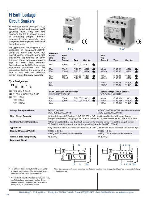
<strong>FI</strong> <strong>Earth</strong> <strong>Leakage</strong><br />
<strong>Circuit</strong> <strong>Breakers</strong><br />
<strong>FI</strong> compact <strong>Earth</strong> <strong>Leakage</strong> <strong>Circuit</strong><br />
<strong>Breakers</strong> detect and interrupt earth<br />
(ground) faults. They are VDE<br />
approved for the European system<br />
of protecting people, animals,<br />
equipment and property from<br />
dangerous line-to-ground and shock<br />
hazard currents.<br />
US applications include ground-fault<br />
protection of equipment (GFPE)<br />
using the 10mA and 30mA fault<br />
current ratings, especially when high<br />
distributed capacitance or other<br />
leakages cause excessive nuisance<br />
trips at lower fault currents.<br />
Applications for the 300mA rating are<br />
equipment protection and fire<br />
prevention, limiting the energy of a<br />
fault to less than the minimum<br />
ignition energy for many materials.<br />
Type Designation<br />
__ __ •<br />
__<br />
<strong>FI</strong><br />
(a) (b) (c)<br />
(a) = 2-2 pole; 4-4 pole<br />
(b) = 1-16A; 2-25A; 3-40A; 4-63A<br />
(c) = 01 - 10mA<br />
= 03 - 30mA<br />
= 30 - 300mA<br />
<strong>FI</strong> 2<br />
Maximum<br />
Rated Fault<br />
Line Trip<br />
Current Current Type Cat. No.<br />
16A 10mA <strong>FI</strong> 21.01 15.921<br />
25A 30mA <strong>FI</strong> 22.03 15.922<br />
25A 300mA <strong>FI</strong> 22.30 15.924<br />
40A 30mA <strong>FI</strong> 23.03 15.923<br />
40A 300mA <strong>FI</strong> 23.30 15.925<br />
63A<br />
63A<br />
<strong>Earth</strong> <strong>Leakage</strong> <strong>Circuit</strong> Breaker<br />
with Auxiliary <strong>Co</strong>ntacts b<br />
25A 30mA <strong>FI</strong> 22.03Y 15.932<br />
40A 30mA <strong>FI</strong> 23.03Y 15.934<br />
63A<br />
<strong>FI</strong> 4 a<br />
Fault<br />
Trip<br />
Current Type Cat. No.<br />
30mA <strong>FI</strong> 42.03 15.926<br />
300mA <strong>FI</strong> 42.30 15.929<br />
30mA <strong>FI</strong> 43.03 15.927<br />
300mA <strong>FI</strong> 43.30 15.930<br />
30mA <strong>FI</strong> 44.03 15.928<br />
300mA <strong>FI</strong> 44.30 15.931<br />
<strong>Earth</strong> <strong>Leakage</strong> <strong>Circuit</strong> Breaker<br />
with Auxiliary <strong>Co</strong>ntacts b<br />
30mA <strong>FI</strong> 42.03Y 15.933<br />
30mA <strong>FI</strong> 43.03Y 15.935<br />
30mA <strong>FI</strong> 44.03Y 15.936<br />
Voltage Rating (maximum)<br />
Short <strong>Circuit</strong> Capacity<br />
Fault Trip Current Calibration<br />
Typical Life<br />
Standard Pack and Weight<br />
Terminal Size Acceptability<br />
Equivalent <strong>Circuit</strong><br />
240VAC, 50/60Hz<br />
415VAC, 50/60Hz (400Hz available on request)<br />
(VDE: 125/220VAC, 50Hz)<br />
(VDE: 220/380VAC, 50Hz)<br />
Up to rated current (RC) 40A = 1.5kA, RC 63A = 2kA. 10kA in combination with series fuse of<br />
European Operation Class gL/gG: RC 16A = 63A fuse, RC 20/40A = 80A fuse, RC 63A = 100A fuse.<br />
<strong>FI</strong> trips are calibrated at less than fault trip current for ensured safety (Typical trip range between<br />
66.6-83.3% fault trip current, e.g., typical trip at 20-25mA for fault RC of 30mA)<br />
Fully functional after 4,000 operations to DIN/VDE 0664 (CEE27) and 16000 additional fault current trips.<br />
1/290g (0.64 lb.); 1/450g (1.0 lb.)<br />
1/390g (0.86 lb.) with auxiliary contact 1/550g (1.21 lb.) with auxiliary contact<br />
16-6 AWG 14-3 AWG<br />
1 N<br />
1 3 5 N<br />
2 N Test<br />
2 4 6 N Test<br />
a For 2-Phase applications, terminal 5 and 6 (next<br />
to Neutral terminals) must be connected to one<br />
phase for the test circuit to be operable.<br />
Note: If the power system has a marked conductor, it must connect through the <strong>FI</strong> and not be grounded at any<br />
point downstream.<br />
b Provided with mounted Auxiliary Switch, one N.O.,<br />
one N.C. isolated feedthrough contact (Form X<br />
double make and Y double break), which adds<br />
9mm (.35 in.) to the width dimension.<br />
30<br />
Altech <strong>Co</strong>rp. ® • 35 Royal Road • Flemington, NJ 08822-6000 • Phone (908)806-9400 • FAX (908)806-9490 • www.altechcorp.com
64mm (2.52 in.)<br />
58mm (2.28 in.)<br />
5.8mm<br />
(0.23 in.)<br />
10.9mm<br />
(0.43 in.)<br />
8mm<br />
(0.31 in.)<br />
13.5mm<br />
(0.53 in.)<br />
13.5mm<br />
(0.53 in.)<br />
13.5mm<br />
(0.53 in.)<br />
R1<br />
22.9mm<br />
(0.90 in.)<br />
1 N<br />
1 3 5 N<br />
R1<br />
72.5mm (2.85 in.)<br />
72.5mm (2.85 in.)<br />
90.5mm (3.56 in.)<br />
45.4mm (1.79in.)<br />
88°<br />
46°<br />
36mm (1.42 in.)<br />
36mm (1.42 in.)<br />
2<br />
N<br />
2<br />
4 6 N<br />
R1<br />
3.2mm<br />
(0.13 in.)<br />
15.7mm<br />
(0.62 in.)<br />
6.5mm<br />
(0.26 in.)<br />
9mm<br />
(0.35 in.)<br />
18mm<br />
(0.71 in.)<br />
9mm<br />
(0.35 in.)<br />
18mm<br />
(0.71 in.)<br />
18mm<br />
(0.71 in.)<br />
18mm<br />
(0.71 in.)<br />
31mm (1.22 in.)<br />
44mm (1.73 in.)<br />
36mm (1.42 in.)<br />
72mm (2.83 in.)<br />
68mm (2.68 in.)<br />
<strong>FI</strong> 2 <strong>FI</strong> 4 <strong>FI</strong> 2 and <strong>FI</strong> 4<br />
Temperature Range<br />
Fluctuating Climate <strong>Co</strong>nditions<br />
Electrical Shock Protection<br />
Environmental Information marked with “Snowflake” approval for -25°C to 40°C (-13°F to 104°F) ambient<br />
temperature. (Temperature effect on RC: for every 10°C temperature rise above 40°C decrease RC by 7%.)<br />
To maximum 45°C, 95% relative humidity.<br />
Uninsulated electrically live parts within 30mm of the operating handle are “finger safe” (terminal screw<br />
heads) and uninsulated live parts within 100mm of the operating handle are “back-of-hand safe” (terminals).<br />
Impact/Shock Protection<br />
Vibration/Seismic Resistance<br />
Housing Class<br />
Non-Sinusoidal Fault<br />
15g with impact force half-cycle sinusoidal and 11ms duration, 18 impacts total with 6 on each principal axis<br />
(3 impacts each face). <strong>FI</strong> is DIN Rail mounted during the test, and electrically loaded with 25% of Fault RC.<br />
Successful testing required no trip during the test, no damage and no loosened parts.<br />
5g, at frequency of 55Hz to 2,000Hz, applied for 35 ± 5 minutes along each of the three principal axes, plus<br />
5 minutes of application at every established critical resonant frequency. <strong>FI</strong> is DIN Rail mounted during the<br />
test, and loaded with 25% Fault RC. To pass, the <strong>FI</strong> did not trip at 25% Fault RC, but did trip between each<br />
of the principal axis tests when the fault current was raised to 125% Fault RC, and there was no damage<br />
and no loosened parts. Suitable for machinery and mobile vehicle applications.<br />
Ingress Protection (IP) Class 40; internal working components and live parts (excluding terminals) are<br />
protected against ingress of solid objects greater than 1mm diameter (class 4-), but have no protection from<br />
ingress of water (class-0).<br />
The <strong>FI</strong> is tested and approval stamped for tripping sensitivity to non-sinusoidal fault currents, which become<br />
zero or almost zero within one cycle of the line frequency. Waveforms and allowed trip-current ranges are as<br />
follows:<br />
1. AC Sinusoidal Fault - 0.5-1.0 times Fault RC<br />
2a. Pulsating DC Fault;<br />
Positive and Negative Half-Waves - 0.35-1.4 times Fault RC<br />
2b. Phased Half-Wave, 90° - 0.25-1.4 times Fault RC<br />
Phased Half-Wave, 135° - 0.11-1.4 times Fault RC<br />
3. Pulsating DC on 6mA<br />
DC (continuous) Base - Max. 1.4 times Fault RC + 6mA<br />
Insulation Category<br />
At VDE rated voltage, suitable for Class C environments with relatively high dust and moisture levels and<br />
little HVAC control, e.g., industrial, commercial, agricultural; on machine tools, hoists, warehouse equipment,<br />
etc.; in boiler rooms, unheated storage, covered shipping/receiving, open workshops, etc.<br />
Altech <strong>Co</strong>rp. ® • 35 Royal Road • Flemington, NJ 08822-6000 • Phone (908)806-9400 • FAX (908)806-9490 • www.altechcorp.com<br />
31