rtS151 remote test Station - System Sensor
rtS151 remote test Station - System Sensor
rtS151 remote test Station - System Sensor

You also want an ePaper? Increase the reach of your titles
YUMPU automatically turns print PDFs into web optimized ePapers that Google loves.
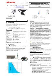
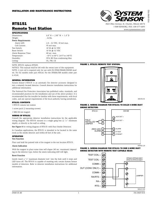
INSTALLATION AND MAINTENANCE INSTRUCTIONS<br />
RTS151<br />
Remote Test <strong>Station</strong><br />
Specifications<br />
Dimensions:<br />
Weight:<br />
Power Requirements<br />
Alarm LED:<br />
Coil Current:<br />
Test Switch:<br />
Reset Switch:<br />
Alarm Response Time:<br />
Temperature:<br />
Humidity:<br />
Listing:<br />
4.8˝ H × 2.90˝ W × 1.4˝ D<br />
.16 lbs.<br />
2.8 – 32 VDC, 10 mA max.<br />
95 mA max.<br />
10 VA @ 32 VDC<br />
10 VA @ 32 VDC<br />
40 sec. max.<br />
–10°C to 60°C (14°F to 140°F)<br />
95% RH Non-condensing Max<br />
UL, FM, CE<br />
NOTE: RTS151 replaces RTS451.<br />
NOTICE: This manual shall be left with the owner/user of this equipment.<br />
NOTE: A <strong>test</strong> coil is required only for use with D2/DNR/DH400/DH500 models.<br />
For D2 models order part #DCoil. For the DH400/500 models order part<br />
is #Coil.<br />
General Information<br />
<strong>System</strong> <strong>Sensor</strong>’s RTS151 is an automatic fire detector accessory designed to<br />
<strong>test</strong> a <strong>remote</strong>ly located detector. Consult detector installation instructions for<br />
additional information.<br />
The National Fire Protection Association has published codes, standards, and<br />
recommended practices for the installation and use of the above product. It is<br />
recommended that the installer be familiar with these requirements, with local<br />
codes, and any special requirements of the local authority having jurisdiction.<br />
RTS151 Contents<br />
1 RTS151 <strong>remote</strong> <strong>test</strong> station<br />
1 screw pack (2 mounting screws)<br />
1 M02-04 <strong>test</strong> magnet<br />
Wiring of RTS151<br />
Consult the appropriate detector installation instructions for the applicable<br />
wiring diagram. The RTS151 mounts to a single gang box (2 1 /2” minimum<br />
depth), or directly to the wall or ceiling.<br />
See Figure 8 for wiring diagram of RTS151 with Duct Smoke Detectors.<br />
In Canadian applications, the RTS151 is intended to be located in the same<br />
room as the smoke detector and within 60 feet of the unit.<br />
Operation<br />
Test Function<br />
Place and hold the painted side of the magnet to the <strong>test</strong> location RTS151.<br />
Alarm Indication<br />
With the magnet in place some time will elapse (40 sec. maximum) depending<br />
on the detector type, before the alarm indicating LED will light.<br />
Reset Function<br />
Gently insert a 1 /8˝ maximum diameter tool into the hole until it stops and<br />
LED turns off. The RTS151 is capable of resetting only certain <strong>System</strong> <strong>Sensor</strong><br />
models of detectors. Refer to detector installation instructions for additional<br />
information.<br />
Figure 1. RTS151 Remote Test <strong>Station</strong>:<br />
3825 Ohio Avenue, St. Charles, Illinois 60174<br />
1-800-SENSOR2, FAX: 630-377-6495<br />
www.systemsensor.com<br />
H0196-01<br />
Figure 2. Wiring Diagram for RTS151 to D4120 4-Wire Duct<br />
Smoke Detector:<br />
RTS151<br />
FIELD<br />
INSTALLED<br />
JUMPER<br />
(RED LED)<br />
ALARM<br />
2<br />
4<br />
1<br />
5<br />
3<br />
19<br />
AUX OUT +<br />
20 AUX OUT –<br />
15 ALARM<br />
11 R TEST<br />
2 R RESET<br />
D4120<br />
H0582-20<br />
Figure 3. Wiring Diagram for RTS151 to DNR 2-Wire Duct<br />
Smoke Detector WITH REMOTE TEST CAPABLE HEAD:<br />
TEST COIL +<br />
TEST COIL –<br />
COMM +<br />
OUT (CONV ONLY) +<br />
COMM –<br />
RA/RTS –<br />
RTS451/RTS451KEY<br />
RTS151/RTS151KEY<br />
1<br />
2<br />
3<br />
JUMPER<br />
I56-0469-014<br />
RA +<br />
4<br />
RTS +<br />
5<br />
H0633-00<br />
D440-01-00 1 I56-0469-014
Figure 4. Wiring Diagram for RTS151 to D2-2Wire Duct Smoke Detector:<br />
MAGNET<br />
TEST<br />
SWITCH<br />
ALARM<br />
LED (RED)<br />
4<br />
5<br />
2<br />
(–)<br />
1 (+)<br />
+ TEST COIL<br />
– TEST COIL<br />
+ IN<br />
+ OUT<br />
– RA<br />
RTS151<br />
(OPTIONAL) REMOTE<br />
+ RA<br />
TEST STATION<br />
+ RTS<br />
D2<br />
METHOD #1 - AUX POWER LOCATED<br />
AT DUCT DETECTOR<br />
–<br />
(–)<br />
(+)<br />
24 VDC<br />
AUX POWER<br />
SUPPLIED<br />
BY USER<br />
(100mA<br />
SUPPLY)<br />
24 VAC (+10%, –15%)<br />
FULL WAVE RECTIFIED,<br />
UNFILTERED POWER<br />
MAY BE USED<br />
24 VDC<br />
AUX POWER<br />
SUPPLIED<br />
BY USER<br />
(100mA<br />
SUPPLY)<br />
24 VAC (+10%, –15%)<br />
FULL WAVE RECTIFIED,<br />
UNFILTERED POWER<br />
MAY BE USED<br />
MAGNET<br />
TEST<br />
SWITCH<br />
ALARM<br />
LED (RED)<br />
RTS151<br />
(OPTIONAL) REMOTE<br />
TEST STATION<br />
4<br />
5<br />
2<br />
(–)<br />
1 (+)<br />
METHOD #2 - AUX POWER LOCATED<br />
AT TEST STATION<br />
+ TEST COIL<br />
– TEST COIL<br />
+ IN<br />
+ OUT<br />
–<br />
– RA<br />
+ RA<br />
+ RTS<br />
D2<br />
NOTE: THE USE OF THE RTS151 REQUIRES THE INSTALLATION OF<br />
AN ACCESSORY COIL, DCOIL, SOLD SEPARATELY.<br />
H0612-11<br />
Figure 5. Wiring diagram for RTS151 to DH100ACDC 4-Wire<br />
Duct Smoke Detector:<br />
Figure 6. Wiring diagram for RTS151 to DH100 2-Wire Duct<br />
Smoke Detector:<br />
DH100ACDC<br />
Alarm Signal +<br />
15<br />
1<br />
RTS151<br />
(Red LED) Alarm<br />
DH100<br />
Test +<br />
1<br />
5<br />
RTS151<br />
Test<br />
Aux. Power –<br />
Reset<br />
20<br />
2<br />
Field<br />
Installed<br />
Jumper<br />
2<br />
3 Reset<br />
4<br />
Test / Reset –<br />
Reset +<br />
RA +<br />
RA –<br />
2<br />
3<br />
4<br />
5<br />
4<br />
3<br />
1<br />
2<br />
Alarm<br />
LED<br />
Reset<br />
Test<br />
11<br />
5<br />
Test<br />
V Out +<br />
6<br />
6<br />
No Connection<br />
H0197-01<br />
H0198-04<br />
Figure 7. Wiring diagram for RTS151 to DH400ACDC Duct<br />
Smoke Detector:<br />
Figure 8. Wiring diagram for RTS151 to BEAM1224/<br />
BEAM1224S Smoke Detector:<br />
DH400ACDC<br />
ALARM SIGNAL (+)<br />
AUX POWER (–)<br />
RESET (–)<br />
TEST (–)<br />
5<br />
6<br />
3<br />
4<br />
FIELD<br />
INSTALLED<br />
JUMPER<br />
RTS151<br />
1<br />
2<br />
4<br />
5<br />
R<br />
E<br />
D<br />
3 RESET<br />
TEST<br />
BEAM1224/BEAM1224S<br />
REMOTE ALARM OUT<br />
AUX (–)<br />
RESET INPUT<br />
REMOTE TROUBLE OUTPUT<br />
TEST INPUT<br />
1<br />
2<br />
3<br />
4<br />
5<br />
T2-1<br />
T2-2<br />
T2-4<br />
T3-3<br />
OPTIONAL YELLOW LED<br />
T2-3<br />
RTS151<br />
1 (RED LED) ALARM<br />
2<br />
RESET<br />
3<br />
4<br />
TEST<br />
5<br />
H0149-02<br />
H0586-03<br />
<strong>System</strong> <strong>Sensor</strong> warrants its enclosed product to be free from defects in materials and<br />
workmanship under normal use and service for a period of three years from date of<br />
manufacture. <strong>System</strong> <strong>Sensor</strong> makes no other express warranty for the enclosed product.<br />
No agent, representative, dealer, or employee of the Company has the authority to increase<br />
or alter the obligations or limitations of this Warranty. The Company’s obligation<br />
of this Warranty shall be limited to the replacement of any part of the product which<br />
is found to be defective in materials or workmanship under normal use and service<br />
during the three year period commencing with the date of manufacture. After phoning<br />
<strong>System</strong> <strong>Sensor</strong>’s toll free number 800-SENSOR2 (736-7672) for a Return Authorization<br />
number, send defective units postage prepaid to: <strong>System</strong> <strong>Sensor</strong>, Returns Department, RA<br />
Three-Year Limited Warranty<br />
#__________, 3825 Ohio Avenue, St. Charles, IL 60174. Please include a note describing<br />
the malfunction and suspected cause of failure. The Company shall not be obligated to<br />
replace units which are found to be defective because of damage, unreasonable use,<br />
modifications, or alterations occurring after the date of manufacture. In no case shall the<br />
Company be liable for any consequential or incidental damages for breach of this or any<br />
other Warranty, expressed or implied whatsoever, even if the loss or damage is caused by<br />
the Company’s negligence or fault. Some states do not allow the exclusion or limitation of<br />
incidental or consequential damages, so the above limitation or exclusion may not apply<br />
to you. This Warranty gives you specific legal rights, and you may also have other rights<br />
which vary from state to state.<br />
D440-01-00 2 I56-0469-014<br />
©2011 <strong>System</strong> <strong>Sensor</strong>