S8JX (50/100/150-W Models) - Tema
S8JX (50/100/150-W Models) - Tema
S8JX (50/100/150-W Models) - Tema

Create successful ePaper yourself
Turn your PDF publications into a flip-book with our unique Google optimized e-Paper software.
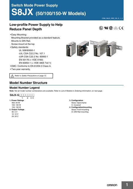
Switch Mode Power Supply<br />
<strong>S8JX</strong> (<strong>50</strong>/<strong>100</strong>/1<strong>50</strong>-W <strong>Models</strong>)<br />
CSM_<strong>S8JX</strong>_OEE_DS_E_1_2<br />
Low-profile Power Supply to Help<br />
Reduce Panel Depth<br />
• Easy Mounting:<br />
Mounting Bracket provided as a standard feature.<br />
Mounts to DIN Rail.<br />
Screw-mount at the top.<br />
• Safety standards:<br />
UL <strong>50</strong>8/609<strong>50</strong>-1<br />
cUL CSA C22.2 No. 107.1<br />
cUR CSA C22.2 No. 609<strong>50</strong>-1<br />
EN <strong>50</strong>178 (= VDE 0160)<br />
EN 609<strong>50</strong>-1 (= VDE 0805 Teil 1)<br />
• EMC: Conforms to EN 61204-3 Class A.<br />
• Two-year warranty.<br />
Refer to Safety Precautions on page 12.<br />
Model Number Structure<br />
Model Number Legend<br />
Note: Not all model number combinations are available. Refer to List of <strong>Models</strong> in Ordering Information, on next page.<br />
<strong>S8JX</strong>-G@@@@@@@<br />
1 2 3 4<br />
1. Power Ratings<br />
0<strong>50</strong>: <strong>50</strong> W<br />
<strong>100</strong>: <strong>100</strong> W<br />
1<strong>50</strong>: 1<strong>50</strong> W<br />
2. Output Voltage<br />
05: 5 V<br />
12: 12 V<br />
24: 24 V<br />
3. Configuration<br />
None: Open-frame<br />
C: Covered<br />
4. Configuration/mounting<br />
None: Front-mounting<br />
D: DIN Rail-mounting<br />
1
Ordering Information<br />
List of <strong>Models</strong><br />
Note: For details on normal stock models, contact your nearest OMRON representative.<br />
Open-frame<br />
Power Supplies<br />
Covered Power<br />
Supplies<br />
Open-frame<br />
Power Supplies<br />
Covered Power<br />
Supplies<br />
Configuration<br />
Front-mounting<br />
DIN Railmounting<br />
Input voltage<br />
<strong>100</strong> to 240 VAC<br />
(free)<br />
Power<br />
ratings<br />
<strong>50</strong> W<br />
Output voltage Output current Model<br />
5 V 10 A <strong>S8JX</strong>-G0<strong>50</strong>05<br />
12 V 4.2 A <strong>S8JX</strong>-G0<strong>50</strong>12<br />
24 V 2.1 A <strong>S8JX</strong>-G0<strong>50</strong>24<br />
5 V 20 A <strong>S8JX</strong>-G<strong>100</strong>05<br />
<strong>100</strong> W 12 V 8.5 A <strong>S8JX</strong>-G<strong>100</strong>12<br />
24 V 4.5 A <strong>S8JX</strong>-G<strong>100</strong>24<br />
1<strong>50</strong> W 24 V 6.5 A <strong>S8JX</strong>-G1<strong>50</strong>24<br />
<strong>50</strong> W<br />
5 V 10 A <strong>S8JX</strong>-G0<strong>50</strong>05C<br />
12 V 4.2 A <strong>S8JX</strong>-G0<strong>50</strong>12C<br />
24 V 2.1 A <strong>S8JX</strong>-G0<strong>50</strong>24C<br />
5 V 20 A <strong>S8JX</strong>-G<strong>100</strong>05C<br />
<strong>100</strong> W 12 V 8.5 A <strong>S8JX</strong>-G<strong>100</strong>12C<br />
24 V 4.5 A <strong>S8JX</strong>-G<strong>100</strong>24C<br />
1<strong>50</strong> W 24 V 6.5 A <strong>S8JX</strong>-G1<strong>50</strong>24C<br />
<strong>50</strong> W<br />
5 V 10 A <strong>S8JX</strong>-G0<strong>50</strong>05D<br />
12 V 4.2 A <strong>S8JX</strong>-G0<strong>50</strong>12D<br />
24 V 2.1 A <strong>S8JX</strong>-G0<strong>50</strong>24D<br />
5 V 20 A <strong>S8JX</strong>-G<strong>100</strong>05D<br />
<strong>100</strong> W 12 V 8.5 A <strong>S8JX</strong>-G<strong>100</strong>12D<br />
24 V 4.5 A <strong>S8JX</strong>-G<strong>100</strong>24D<br />
1<strong>50</strong> W 24 V 6.5 A <strong>S8JX</strong>-G1<strong>50</strong>24D<br />
<strong>50</strong> W<br />
5 V 10 A <strong>S8JX</strong>-G0<strong>50</strong>05CD<br />
12 V 4.2 A <strong>S8JX</strong>-G0<strong>50</strong>12CD<br />
24 V 2.1 A <strong>S8JX</strong>-G0<strong>50</strong>24CD<br />
5 V 20 A <strong>S8JX</strong>-G<strong>100</strong>05CD<br />
<strong>100</strong> W 12 V 8.5 A <strong>S8JX</strong>-G<strong>100</strong>12CD<br />
24 V 4.5 A <strong>S8JX</strong>-G<strong>100</strong>24CD<br />
1<strong>50</strong> W 24 V 6.5 A <strong>S8JX</strong>-G1<strong>50</strong>24CD<br />
<strong>S8JX</strong><br />
2
<strong>S8JX</strong><br />
Ratings, Characteristics, and Functions<br />
Input specification<br />
<strong>100</strong> to 240 V input<br />
Item Power ratings *1 <strong>50</strong> W <strong>100</strong> W 1<strong>50</strong> W<br />
Efficiency (typical) 76% min. 86% min.<br />
Input<br />
Output *4<br />
Additional<br />
functions<br />
Other<br />
Voltage *2<br />
Frequency *2<br />
Current *3<br />
<strong>100</strong> to 240 VAC (85 to 264 VAC)<br />
<strong>100</strong> to 370 VDC<br />
Note: This range is not applicable for the safety standards.<br />
<strong>50</strong>/60 Hz (47 to 4<strong>50</strong> Hz)<br />
<strong>100</strong> V input 1.4 A 2.5 A 3.5 A<br />
200 V input 0.8 A 1.5 A 2.1 A<br />
Power factor ---<br />
Harmonic current emissions ---<br />
Leakage current *3<br />
Inrush current (for a<br />
cold start at 25°C) *3<br />
Noise filter<br />
Voltage adjustment range *5<br />
Ripple *3<br />
Input variation influence<br />
Load variation influence<br />
Temperature variation influence<br />
Startup time<br />
Hold time *3<br />
Overload protection *6<br />
Overvoltage protection *7<br />
Overheat protection<br />
Parallel operation<br />
Series operation<br />
<strong>100</strong> V input 0.5 mA max.<br />
200 V input 1 mA max.<br />
<strong>100</strong> V input 20 A max.<br />
200 V input 40 A max.<br />
Protective circuit operation indicator<br />
Ambient operating temperature<br />
Storage temperature<br />
Yes<br />
−10% to 15% (with V. ADJ)<br />
2% (p-p) max.<br />
0.4% max.<br />
0.8% max. (0 to <strong>100</strong>% load, rated input voltage)<br />
0.05%/°C max. (at rated input and output)<br />
<strong>50</strong>0 ms max. (up to 90% of output voltage at rated input and output)<br />
20 ms min.<br />
105% to 160% of rated load current, voltage drop, intermittent, automatic reset<br />
Yes<br />
No<br />
No<br />
Yes (For up to two Power Supplies; external diodes required.)<br />
No<br />
Refer to the derating curve in Engineering Data on page 6 (with no icing or condensation)<br />
−25 to 65°C (with no icing or condensation)<br />
Ambient operating humidity 25% to 85% (Storage humidity: 25% to 90%)<br />
Dielectric strength<br />
Insulation resistance<br />
Vibration resistance<br />
Shock resistance<br />
Output indicator<br />
Conducted Emissions *3<br />
Radiated Emissions<br />
Approved standards<br />
SEMI<br />
3.0 kVAC for 1 min. (between all inputs and outputs; detection current: 20 mA)<br />
2.0 kVAC for 1 min. (between all inputs and PE terminals; detection current: 20 mA)<br />
1.0 kVAC for 1 min. (between all outputs and PE terminals; detection current: 20 mA)<br />
<strong>100</strong> MΩ min. (between all outputs and all inputs/PE terminals) at <strong>50</strong>0 VDC<br />
10 to 55 Hz, 0.375-mm single amplitude for 2h each in X, Y, and Z directions<br />
1<strong>50</strong>m/s 2 , 3 times each in ±X, ±Y, ±Z directions<br />
Yes (Color: Green)<br />
Conforms to EN 5<strong>50</strong>11 Group 1 Class A and based on FCC Class A<br />
Conforms to EN 5<strong>50</strong>11 Group 1 Class A<br />
UL <strong>50</strong>8 (Listing), UL 609<strong>50</strong>-1<br />
cUL: CSA C22.2 No.107.1<br />
cUR: CSA C22.2 No. 609<strong>50</strong>-1<br />
EN/VDE: EN<strong>50</strong>178 (= VDE 0160), EN 609<strong>50</strong>-1 (= VDE 0805 Teil 1)<br />
(Terminal block: Based on VDE 0106/P<strong>100</strong>)<br />
SEMI F47-0200 (200-VAC input)<br />
Weight *8 300 g max. 5<strong>50</strong> g max. 600 g max.<br />
*1. When a load is connected that has a built-in DC-DC converter, the overload protection may operate at startup and the Power Supply may not<br />
start. Refer to Overload Protection on page 7.<br />
*2. Do not use an Inverter output for the Power Supply. Inverters with an output frequency of <strong>50</strong>/60 Hz are available, but the rise in the internal<br />
temperature of the Power Supply may result in ignition or burning.<br />
*3. Rated input voltage: <strong>100</strong> or 200 VAC at <strong>100</strong>% load.<br />
*4. Output characteristics: Specified at power supply output terminals.<br />
*5. If the output voltage adjuster (V. ADJ) is turned, the voltage will increase by more than +15% of the voltage adjustment range. When adjusting<br />
the output voltage, confirm the actual output voltage from the Power Supply and be sure that load is not damaged.<br />
*6. For details, refer to Overload Protection on page 7.<br />
*7. To reset the protection, turn OFF the input power for seven minutes or longer and then turn it back ON.<br />
*8. The weight indicated is for Front-mounting, Open-frame Power Supplies.<br />
3
Connections<br />
Block Diagrams<br />
<strong>S8JX</strong>-G0<strong>50</strong>@@@@ (<strong>50</strong> W)<br />
<strong>S8JX</strong><br />
AC (L)<br />
INPUT<br />
AC (N)<br />
Fuse<br />
6.3 A<br />
Inrush current<br />
protection<br />
Noise<br />
filter<br />
Rectifier<br />
Smoothing<br />
circuit<br />
Rectifier/<br />
Smoothing circuit<br />
+V<br />
DC OUTPUT<br />
−V<br />
Drive control<br />
Circuit<br />
Overcurrent<br />
detection<br />
circuit<br />
Voltage<br />
detection<br />
Photocoupler<br />
Overvoltage<br />
detection circuit<br />
<strong>S8JX</strong>-G<strong>100</strong>@@@@ (<strong>100</strong> W)<br />
AC (L)<br />
INPUT<br />
AC (N)<br />
Fuse<br />
8 A<br />
Inrush current<br />
protection<br />
Noise<br />
filter<br />
Rectifier<br />
Smoothing<br />
circuit<br />
Rectifier/<br />
Smoothing circuit<br />
+V<br />
DC OUTPUT<br />
−V<br />
Drive control<br />
Circuit<br />
Overcurrent<br />
detection<br />
circuit<br />
Voltage<br />
detection<br />
Photocoupler<br />
Overvoltage<br />
detection circuit<br />
<strong>S8JX</strong>-G1<strong>50</strong>24@@ (1<strong>50</strong> W)<br />
INPUT<br />
AC (L)<br />
AC (N)<br />
Fuse<br />
10 A<br />
Noise<br />
filter<br />
Inrush current<br />
protection<br />
Rectifier<br />
Smoothing<br />
circuit<br />
Rectifier/<br />
Smoothing circuit<br />
+V<br />
DC OUTPUT<br />
−V<br />
Drive control<br />
Circuit<br />
Overcurrent<br />
detection<br />
circuit<br />
Voltage<br />
detection<br />
Photocoupler<br />
Overvoltage<br />
detection circuit<br />
4
Construction and Nomenclature<br />
Nomenclature<br />
<strong>50</strong>/<strong>100</strong>/1<strong>50</strong>-W Power Supplies<br />
<strong>S8JX</strong><br />
D<br />
E<br />
A<br />
C<br />
B<br />
+V<br />
−V<br />
AC (L)<br />
AC (N)<br />
No. Name Function<br />
1 DC output terminals (−V), (+V) Connect the load lines to these terminals.<br />
2 AC input terminals (L), (N) Connect the input lines to these terminals. *1<br />
3 Protective Earth terminal (PE) ( ) Connect the ground line to these terminals. *2<br />
4 Output voltage adjuster (V. ADJ) Use to adjust the voltage.<br />
5 Output indicator (DC ON: Green) Lights green while a direct current (DC) output is ON.<br />
*1. The fuse is located on the (L) side.<br />
*2. This is the protective earth terminal specified in the safety standards. Always ground this terminal.<br />
Note: The <strong>S8JX</strong>-G0<strong>50</strong>24CD is shown above.<br />
Reference Values<br />
Reliability<br />
(MTBF)<br />
Definition<br />
Life<br />
expectancy<br />
Definition<br />
Value<br />
<strong>50</strong> W: 300,000 hrs<br />
<strong>100</strong> W: 270,000 hrs<br />
1<strong>50</strong> W: 2<strong>50</strong>,000 hrs<br />
MTBF stands for Mean Time Between Failures,<br />
which is calculated according to the probability of<br />
accidental device failures, and indicates reliability of<br />
devices.<br />
Therefore, it does not necessarily represent a life of<br />
the product.<br />
10 yrs. min.<br />
The life expectancy indicates average operating<br />
hours under the ambient temperature of 40°C and a<br />
load rate of <strong>50</strong>%. Normally this is determined by the<br />
life expectancy of the built-in aluminum electrolytic<br />
capacitor.<br />
5
Engineering Data<br />
Derating Curves (Standard Mounting)<br />
<strong>50</strong>/<strong>100</strong>/1<strong>50</strong>-W Power Supplies<br />
Open-frame Power Supplies Covered Power Supplies<br />
Load rate (%)<br />
120<br />
<strong>100</strong><br />
A<br />
Load rate (%)<br />
120<br />
<strong>100</strong><br />
A<br />
<strong>S8JX</strong><br />
80<br />
80<br />
60<br />
60<br />
40<br />
40<br />
20<br />
20<br />
0<br />
−20 −10 0 10 20 30 40 <strong>50</strong> 60 70 80<br />
Ambient Temperature (°C)<br />
0<br />
−20 −10 0 10 20 30 40 <strong>50</strong> 60 70 80<br />
Ambient Temperature (°C)<br />
Note: 1. Internal parts may occasionally deteriorate or be damaged. Do not use the Power Supply in areas outside the derating<br />
curve (i.e., the area shown by shading A in the above graph).<br />
2. If there is a derating problem, use forced air-cooling.<br />
Mounting<br />
Standard Mounting: Front-mounting<br />
Standard Mounting: DIN Rail-mounting<br />
Standard Mounting: Bottom-mounting<br />
Standard Mounting: Horizontal-mounting<br />
*<br />
*<br />
*<br />
Note: 1. Improper mounting will interfere with heat dissipation and may occasionally result in deterioration or damage of internal parts. Use the<br />
standard mounting method only.<br />
2. When mounting the Power Supply, mounting it to a metal plate (*) is recommended.<br />
3. Install the Power Supply so that the air flow circulates around the Power Supply, as the Power Supply is designed to radiate heat by<br />
means of natural air flow.<br />
Mounting (<strong>50</strong>/<strong>100</strong>/1<strong>50</strong>-W Power Supplies)<br />
The following three mounting methods are possible.<br />
A. Side-mounting<br />
B. Bottom-mounting<br />
C. Front-mounting: See information on mounting bracket.<br />
B<br />
A<br />
6
<strong>S8JX</strong><br />
Overload Protection<br />
The Power Supply is provided with an overload protection function<br />
that protects the power supply from possible damage by overcurrent.<br />
When the output current rises above 105% min. of the rated current,<br />
the protection function is triggered, decreasing the output voltage.<br />
When the output current falls within the rated range, the overload<br />
protection function is automatically cleared.<br />
(Reference value)<br />
<strong>50</strong> W to 1<strong>50</strong> W<br />
Overvoltage Protection<br />
Consider the possibility of an overvoltage and design the system so<br />
that the load will not be subjected to an excessive voltage even if the<br />
feedback circuit in the power supply fails. When an excessive voltage<br />
that is approximately 130% of the rated voltage or more is output, the<br />
output voltage is shut OFF, preventing damage to the load due to<br />
overvoltage. Reset the input power by turning it OFF for at least seven<br />
minutes and then turning it back ON again.<br />
(Reference value)<br />
Output voltage (V)<br />
Output voltage (V)<br />
Overvoltage protection<br />
Operating<br />
0<br />
Intermittent operation<br />
<strong>50</strong><br />
<strong>100</strong><br />
Load rate (%)<br />
Rated output<br />
Voltage<br />
Variable range<br />
Note: 1. When a load is connected that has a built-in DC-DC<br />
converter, the overload protection may operate at startup<br />
and the power supply may not start.<br />
2. Internal parts may occasionally deteriorate or be damaged<br />
if a short-circuited or overcurrent state continues during<br />
operation.<br />
3. Internal parts may possibly deteriorate or be damaged if the<br />
Power Supply is used for applications with frequent inrush<br />
current or overloading at the load end. Do not use the Power<br />
Supply for such applications.<br />
0 V<br />
Note: Do not turn ON the power again until the cause of the<br />
overvoltage has been removed.<br />
Inrush Current, Startup Time, Output Hold Time<br />
Input ON<br />
Input OFF<br />
AC input<br />
voltage<br />
Inrush current on input application<br />
AC input<br />
current<br />
90% 96.5%<br />
Output<br />
voltage<br />
Startup time<br />
Hold time (20 ms min.)<br />
Note: A maximum startup time of <strong>50</strong>0 ms is required. Construct a<br />
system configuration that considers the startup time of other<br />
devices.<br />
7
<strong>S8JX</strong><br />
Dimensions<br />
(Unit: mm)<br />
Front-mounting <strong>Models</strong><br />
<strong>S8JX</strong>-G0<strong>50</strong>@@ (<strong>50</strong> W)<br />
<strong>S8JX</strong>-G0<strong>50</strong>@@C (<strong>50</strong> W)<br />
Label<br />
10 max. <strong>100</strong>±1<br />
5 max.<br />
Panel mounting holes dimensions<br />
Surface screw mounting<br />
8.2<br />
9.5<br />
3.5<br />
Two, M3<br />
75±0.5<br />
92±1<br />
Side<br />
Mounting<br />
75±0.5<br />
Five, M3.5<br />
Cover<br />
36±1<br />
4.5<br />
3.5 dia.<br />
92±0.5<br />
8<br />
Bottom<br />
Mounting<br />
92±0.5<br />
Two, M3<br />
40±1<br />
4.5<br />
92±0.5<br />
92±0.5<br />
3.5 dia.<br />
3.5<br />
Two, M3<br />
(Depth 4 mm max.)<br />
26.5<br />
20<br />
20<br />
65±0.5<br />
<strong>S8JX</strong>-G<strong>100</strong>@@ (<strong>100</strong> W)<br />
<strong>S8JX</strong>-G<strong>100</strong>@@C (<strong>100</strong> W)<br />
<strong>S8JX</strong>-G1<strong>50</strong>24 (1<strong>50</strong> W)<br />
<strong>S8JX</strong>-G1<strong>50</strong>24C (1<strong>50</strong> W)<br />
Label<br />
8.2<br />
9.5<br />
10 max. 1<strong>50</strong>±1<br />
<strong>100</strong> W<br />
1<strong>50</strong> W<br />
<strong>100</strong>·1<strong>50</strong> W<br />
3.5<br />
5 max.<br />
Panel mounting holes dimensions<br />
Surface screw mounting<br />
Two, M3<br />
75±0.5<br />
92±1<br />
Side<br />
Mounting<br />
75±0.5<br />
Five, M3.5<br />
Cover<br />
48±1<br />
<strong>50</strong>±1<br />
3.5 dia.<br />
5 141±0.5<br />
5 141±0.5<br />
8<br />
Bottom<br />
Mounting<br />
Two, M3<br />
141±0.5<br />
141±0.5<br />
Two, M3<br />
(Depth 4 mm max.)<br />
3.5 dia.<br />
3.5<br />
28<br />
16<br />
122±0.5<br />
8
<strong>S8JX</strong><br />
Mounting Bracket Provided with Front-mounting Power Supplies<br />
<strong>50</strong> to 1<strong>50</strong> W (Provided)<br />
Front-mounting Bracket<br />
1.5<br />
9<br />
60<br />
Dimensions<br />
11<br />
4.6 15±0.2<br />
Two, 3.5 dia.<br />
74<br />
Mounting<br />
dimensions<br />
60<br />
Two, M3<br />
Front-mounting Method<br />
Temporarily attach the enclosed mounting<br />
bracket as shown in the illustration on the right,<br />
hook the holes (parts a) in the Power Supply on<br />
hooks on the mounting bracket (parts b), and<br />
secure the Power Supply with two mounting<br />
screws.<br />
Power Supply<br />
Note: Mounting screws are<br />
not provided.<br />
a<br />
b<br />
Mounting bracket<br />
5<br />
20<br />
31.5<br />
4.6<br />
11<br />
20<br />
b<br />
4.7<br />
15<br />
t = 1.0<br />
20.5<br />
Material: Stainless steel<br />
a<br />
Mounting Brackets (Order Separately)<br />
Name<br />
Mounting Bracket A (bottom mounting for <strong>50</strong>-W models)<br />
Mounting Bracket B (bottom mounting for <strong>100</strong>-W 24-V models)<br />
Mounting Bracket C (bottom mounting for <strong>100</strong>-W 5-V and 12-V models and 1<strong>50</strong>-W models)<br />
Mounting Bracket D (bottom mounting for <strong>100</strong>-W 5-V and 12-V models and 1<strong>50</strong>-W models)<br />
Note: Mounting brackets (A, B, C, and D) are compatible with the mounting holes of the S82J.<br />
Model<br />
S82Y-JX05B<br />
S82Y-JX10B<br />
S82Y-JX15B<br />
S82Y-JX15F<br />
Mounting Bracket A (Bottom-mounting for <strong>50</strong>-W <strong>Models</strong>)<br />
S82Y-JX05B<br />
Using the Mounting Bracket<br />
6.5<br />
3.5 dia.<br />
161<br />
1<strong>50</strong>.5±0.5<br />
R2<br />
R1.75 R0.5<br />
3.5 40<br />
28<br />
B<br />
Thickness = 2<br />
B<br />
A<br />
A<br />
Screws Used<br />
A: Enclosed (two places)<br />
Be sure to use the enclosed screws.<br />
Mounting screw tightening torque<br />
(recommended): 0.49 N·m<br />
B: M3 (two places)<br />
9
<strong>S8JX</strong><br />
Mounting Bracket B (Bottom-mounting for <strong>100</strong>-W 24-V <strong>Models</strong>)<br />
S82Y-JX10B<br />
Using the Mounting Bracket<br />
6.5<br />
170<br />
160±0.5<br />
R2<br />
4.5 dia.<br />
R2.25 R0.5<br />
4.5 <strong>50</strong><br />
28<br />
B<br />
Thickness = 2<br />
B<br />
A<br />
Screws Used<br />
A: Enclosed (two places)<br />
Be sure to use the enclosed screws.<br />
Mounting screw tightening torque<br />
(recommended): 0.49 N·m<br />
B: M4 (two places)<br />
A<br />
Mounting Bracket C (Bottom-mounting for <strong>100</strong>-W 5-V and 12-V <strong>Models</strong> and 1<strong>50</strong>-W <strong>Models</strong>)<br />
S82Y-JX15B<br />
Using the Mounting Bracket<br />
4.5 dia.<br />
188<br />
178±0.5<br />
R2.25<br />
3<br />
R0.5<br />
4.5<br />
<strong>50</strong><br />
35<br />
R2<br />
Thickness = 2<br />
B<br />
B<br />
A<br />
A<br />
Screws Used<br />
A: Enclosed (two places)<br />
Be sure to use the enclosed screws.<br />
Mounting screw tightening torque<br />
(recommended): 0.49 N·m<br />
B: M4 (two places)<br />
Mounting Bracket D (Front-mounting for <strong>100</strong>-W 5-V and 12-V <strong>Models</strong> and 1<strong>50</strong>-W <strong>Models</strong>)<br />
S82Y-JX15F<br />
Using the Mounting Bracket<br />
54<br />
45.6<br />
4.5<br />
45<br />
25 5 dia.<br />
B<br />
A<br />
119<br />
110±0.5<br />
A<br />
Thickness = 1.6<br />
B<br />
Screws Used<br />
A: Enclosed (two places)<br />
Be sure to use the enclosed screws.<br />
Mounting screw tightening torque<br />
(recommended): 0.49 N·m<br />
B: M4 (two places)<br />
10
<strong>S8JX</strong><br />
DIN Rail-mounting <strong>Models</strong><br />
<strong>S8JX</strong>-G0<strong>50</strong>@@D (<strong>50</strong> W)<br />
<strong>S8JX</strong>-G0<strong>50</strong>@@CD (<strong>50</strong> W)<br />
6 max. 44±1 10 max. <strong>100</strong>±1<br />
Label<br />
14.5 max.<br />
8.2<br />
9.5<br />
5 max.<br />
92±1<br />
Five, M3.5<br />
Cover<br />
47<br />
36±1<br />
40±1<br />
108.6<br />
7 (Sliding: 16.6 max.)<br />
<strong>S8JX</strong>-G<strong>100</strong>@@D (<strong>100</strong> W)<br />
<strong>S8JX</strong>-G<strong>100</strong>@@CD (<strong>100</strong> W)<br />
<strong>S8JX</strong>-G1<strong>50</strong>24D (1<strong>50</strong> W)<br />
<strong>S8JX</strong>-G1<strong>50</strong>24CD (1<strong>50</strong> W)<br />
6 max. <strong>50</strong>±1<br />
Label<br />
8.2<br />
9.5<br />
10 max. 1<strong>50</strong>±1<br />
<strong>100</strong> W<br />
1<strong>50</strong> W<br />
<strong>100</strong>·1<strong>50</strong> W<br />
14.5 max.<br />
5 max.<br />
92±1<br />
Five, M3.5<br />
47<br />
Cover<br />
48±1<br />
<strong>50</strong>±1<br />
158.6<br />
7 (Sliding: 16.6 max.)<br />
DIN Rail (Order Separately)<br />
Mounting Rail<br />
(Material: Aluminum)<br />
4.5<br />
7.3±0.15<br />
35±0.3<br />
27±0.15<br />
15 25 25<br />
25 25 15 (5) *<br />
1<br />
10 10<br />
1,000 (<strong>50</strong>0) ∗<br />
* Value in parentheses are for PFP-<strong>50</strong>N.<br />
Model<br />
PFP-<strong>100</strong>N<br />
PFP-<strong>50</strong>N<br />
Mounting Rail<br />
(Material: Aluminum)<br />
16<br />
4.5<br />
35±0.3<br />
15 25 25<br />
25 25 15 1 1.5<br />
10 10<br />
1,000<br />
27<br />
24<br />
29.2<br />
Model<br />
PFP-<strong>100</strong>N2<br />
End Plate<br />
M4 × 8<br />
panhead<br />
screw<br />
<strong>50</strong><br />
11.5<br />
10<br />
M4 spring<br />
washer<br />
1<br />
35.5 35.5<br />
1.8<br />
Note: 1. If there is a possibility that the Unit will be subject to vibration or shock, use a steel DIN Rail. Otherwise, metallic filings may result from<br />
aluminum abrasion.<br />
2. If the Unit may be subjected to sliding to either side, attach an End Plate (model PFP-M) on each side of the Unit.<br />
10<br />
6.2<br />
1.3<br />
4.8<br />
1.8<br />
Model<br />
PFP-M<br />
11
Safety Precautions<br />
Refer to Safety Precautions for All Power Supplies.<br />
CAUTION<br />
Minor electric shock, fire, or Product failure may<br />
occasionally occur. Do not disassemble, modify, or<br />
repair the Product to touch the interior of the<br />
Product.<br />
Minor burns may occasionally occur. Do not touch<br />
the Product while power is being supplied or<br />
immediately after power is turned OFF.<br />
Fire may occasionally occur. Tighten terminal screws<br />
to the specified torque of 1.13 N·m.<br />
Minor injury due to electric shock may occasionally<br />
occur. Do not touch the terminals while power is<br />
being supplied. Always close the terminal cover after<br />
wiring.<br />
Minor electric shock, fire, or Product failure may<br />
occasionally occur. Do not allow any pieces of metal<br />
or conductors or any clippings or cuttings resulting<br />
from installation work to enter the Product.<br />
Precautions for Safe Use<br />
Mounting<br />
• Take adequate measures to ensure proper heat dissipation to<br />
increase the long-term reliability of the Product.<br />
• Be sure to allow convection in the atmosphere around devices<br />
when mounting. Do not use in locations where the ambient<br />
temperature exceeds the range of the derating curve.<br />
• When cutting out holes for mounting, make sure that cuttings do<br />
not enter the interior of the Products.<br />
• Improper mounting will interfere with heat dissipation and may<br />
occasionally result in deterioration or damage of internal parts. Use<br />
the standard mounting method only.<br />
• The internal parts may occasionally deteriorate and be broken due<br />
to adverse heat radiation. Do not loosen the screw on the side face<br />
of the main body.<br />
• When mounting two or more Power Supplies side-by-side, allow at<br />
least 20 mm spacing between them.<br />
• Use the metal plate as the mounting panel.<br />
Standard Mounting<br />
(Front-mounting and DIN Rail-mounting)<br />
*2<br />
Standard Mounting<br />
(Horizontal Mounting)<br />
*1<br />
*1<br />
*1<br />
Standard Mounting<br />
(Bottom-mounting)<br />
*3<br />
*2<br />
*1<br />
*1<br />
<strong>S8JX</strong><br />
Wiring<br />
• Connect the ground completely. A protective earthing terminal<br />
stipulated in safety standards is used. Electric shock or malfunction<br />
may occur if the ground is not connected completely.<br />
• Minor fire may possibly occur. Ensure that input and output<br />
terminals are wired correctly.<br />
• Do not apply more than 75 N force to the terminal block when<br />
tightening it.<br />
• Be sure to remove the sheet covering the Product for machining<br />
before power-ON so that it does not interfere with heat dissipation.<br />
• Use the following material for the wires to be connected to the<br />
<strong>S8JX</strong> to prevent smoking or ignition caused by abnormal loads.<br />
Recommended Wire Type<br />
• Use a wire size of AWG12 to AWG16 (a cross section of 1.309 to<br />
3.309 mm 2 ).<br />
• Use wires with a UL-certified temperature of a t least 60°C or 60/<br />
75°C.<br />
• Use copper conductors only.<br />
Installation Environment<br />
• Do not use the Power Supply in locations subject to shocks or<br />
vibrations. In particular, install the Power Supply as far away as<br />
possible from contactors or other devices that are a vibration<br />
source.<br />
• Install the Power Supply well away from any sources of strong,<br />
high-frequency noise and surge.<br />
Ambient Operating and Storage Environments<br />
• Store the Power Supply at a temperature of −25 to 65°C and a<br />
humidity of 25% to 90%.<br />
• The Internal parts may occasionally deteriorate or be damaged.<br />
Do not use the Power Supply outside the derating range (i.e., the<br />
area shown by shading A in the derating curve diagram on<br />
page 6.)<br />
• Use the Power Supply at a humidity of 25% to 85%.<br />
• Do not use the Power Supply in locations subject to direct sunlight.<br />
• Do not use locations where liquids, foreign matter, or corrosive<br />
gases may enter the interior of the Product.<br />
Overload Protection<br />
• Internal parts may possibly deteriorate or be damaged if a shortcircuited<br />
or overload state continues during operation.<br />
• Internal parts may possibly deteriorate or be damaged if the Power<br />
Supply is used for applications with frequent inrush current or<br />
overloading at the load end. Do not use the Power Supply for such<br />
applications.<br />
Charging a Battery<br />
When connecting a battery at the load, connect an overcurrent<br />
limiting circuit and overvoltage protection circuit.<br />
Output Voltage Adjuster (V.ADJ)<br />
• The output voltage adjuster (V.ADJ) may possibly be damaged if it<br />
is turned with unnecessary force. Do not turn the adjuster with<br />
excessive force.<br />
• After completing output voltage adjustment, be sure that the output<br />
capacity or output current does not exceed the rated output<br />
capacity or rated output current.<br />
*3<br />
*2<br />
*1<br />
*1. Convection of air<br />
*2. 20 mm max.<br />
*3. Use a metal plate as the<br />
mounting surface.<br />
12
<strong>S8JX</strong><br />
DIN Rail-mounting<br />
To mount the Power Supply to a DIN<br />
Rail, pull down the rail stopper until<br />
you hear it clicks open, hook portion<br />
(A) of the Power Supply onto the DIN<br />
Rail, press the Power Supply in<br />
direction (B), and then push up the rail<br />
stopper to lock the Power Supply in<br />
place.<br />
To dismount the Power Supply, pull<br />
down portion (C) with a flat-blade<br />
screwdriver and pull out the Power<br />
Supply.<br />
(A)<br />
30 mm min.<br />
(B)<br />
(C)<br />
Track stopper<br />
In Case There Is No Output Voltage<br />
The possible cause for no output voltage may be that the overcurrent<br />
or overvoltage protection has operated. The internal protection may<br />
operate if a large amount of surge voltage such as a lightening surge<br />
occurs while turning ON the Power Supply.<br />
In case there is no output voltage, please check the following points<br />
before contacting us:<br />
• Checking overcurrent protected status:<br />
Check whether the load is in overcurrent status or is shortcircuited.<br />
Remove wires to load when checking.<br />
• Checking overvoltage or internal protection:<br />
Turn the power supply OFF once, and leave it OFF for at least 7<br />
minutes. Then turn it ON again to see if this clears the condition.<br />
Series Operation<br />
Two power supplies can be connected in series. The (±) voltage<br />
output can be accomplished with two Power Supplies.<br />
Series Operation Output Voltage (±)<br />
AC (L)<br />
+V<br />
AC (L)<br />
+V<br />
AC (N)<br />
−V<br />
AC (N)<br />
−V<br />
AC (L)<br />
+V<br />
AC (L)<br />
+V<br />
AC (N)<br />
−V<br />
AC (N)<br />
−V<br />
Note: 1. If the load is short-circuited, a reverse voltage will be<br />
generated inside the Power Supply. If this occurs the Power<br />
Supply may possibly deteriorate or be damaged. Always<br />
connect a diode as shown in the figure. Select a diode<br />
having the following ratings.<br />
Type<br />
Dielectric strength (VRRM)<br />
Schottky Barrier diode<br />
Twice the rated output voltage or above<br />
Forward current (IF) Twice the rated output current or above<br />
2. Although Products having different specifications can be<br />
connected in series, the current flowing through the load<br />
must not exceed the smaller rated output current.<br />
Parallel Operation<br />
The Product is not designed for parallel operation.<br />
Parallel Operation<br />
AC (L)<br />
AC (N)<br />
+V<br />
−V<br />
AC (L)<br />
AC (N)<br />
+V<br />
−V<br />
13
Typical Values<br />
For Reference Only<br />
<strong>S8JX</strong><br />
Item<br />
Efficiency<br />
Current<br />
Power ratings<br />
<strong>50</strong> W <strong>100</strong> W 1<strong>50</strong> W<br />
5-V models 80% 81% ---<br />
12-V models 85% 86% ---<br />
24-V models 86% 88% 90%<br />
0.6 A 1.1 A 1.9 A<br />
Input<br />
Leakage current<br />
230 V input<br />
0.35 mA 0.30 mA 0.45 mA<br />
Inrush current<br />
(See Note 1.)<br />
40 A 37 A 42 A<br />
5-V models 0.60%(p-p) 1.25%(p-p) ---<br />
f = 20 MHz<br />
measuring<br />
12-V models 0.30%(p-p) 0.<strong>50</strong>%(p-p) ---<br />
Ripple<br />
24-V models 0.15%(p-p) 0.25%(p-p) 0.45%(p-p)<br />
5-V models 0.75%(p-p) 1.<strong>50</strong>%(p-p) ---<br />
f = <strong>100</strong> MHz<br />
12-V models 0.35%(p-p) 0.70%(p-p) ---<br />
measuring<br />
Output<br />
24-V models 0.20%(p-p) 0.40%(p-p) 0.60%(p-p)<br />
Start up time<br />
(See note 1.)<br />
Hold time<br />
(See note 1.)<br />
at <strong>100</strong>% load 210 ms 220 ms 2<strong>50</strong> ms<br />
at <strong>100</strong>% load<br />
5-V models 190 ms 180 ms ---<br />
12-V models 190 ms 170 ms ---<br />
24-V models 210 ms 170 ms 210 ms<br />
Note: 1. Refer to the Engineering Data on page 6 and 7 for details.<br />
2. The typical values indicate the values for an input condition of 230 VAC. All items are measured at a frequency of <strong>50</strong> Hz.<br />
ALL DIMENSIONS SHOWN ARE IN MILLIMETERS.<br />
To convert millimeters into inches, multiply by 0.03937. To convert grams into ounces, multiply by 0.03527.<br />
In the interest of product improvement, specifications are subject to change without notice.<br />
14