Electrical Power Transmission and Distribution ..
Electrical Power Transmission and Distribution ..
Electrical Power Transmission and Distribution ..

Create successful ePaper yourself
Turn your PDF publications into a flip-book with our unique Google optimized e-Paper software.
"Page No ... J<br />
USN<br />
INEWSCmME<br />
Fifth Semester B.E. Degree.Exalllination, Dec. 06/ .Jan. 07<br />
" ",:Elec~ric~I <strong>and</strong> Electronics Engineering<br />
<strong>Electrical</strong> <strong>Power</strong> <strong>Transmission</strong> <strong>and</strong> <strong>Distribution</strong><br />
EE53<br />
--.---:;::<br />
~<br />
Time: 3 hrs.] [Max. Marks: 100<br />
,NGte: '.Answer any FIVE full quesf!.ons.<br />
1 a. What are the advantages of high voltage ac transmission? (05 Marks)<br />
b. Derive the expression for sag in over-head conductors for conductors at different<br />
levels. (07 Marks)<br />
c. Two towers of height above water level 95 m <strong>and</strong> 70 m respectively support the line<br />
conductors at a river crossing. The horizontal distance between towers is 400 m. If<br />
the tension in the conductor is 1100 kg<strong>and</strong> its weight is 0.8 kg/m" calculate: i) Sag at<br />
lower "shppoit ii)'Sag' at upper support iii) Clearance of the lowest point on the<br />
trajectory-from water level.' . (08 Marks)<br />
2 a. Explain the terms Self GMD <strong>and</strong> Mutual GMD .• (OSMarks)<br />
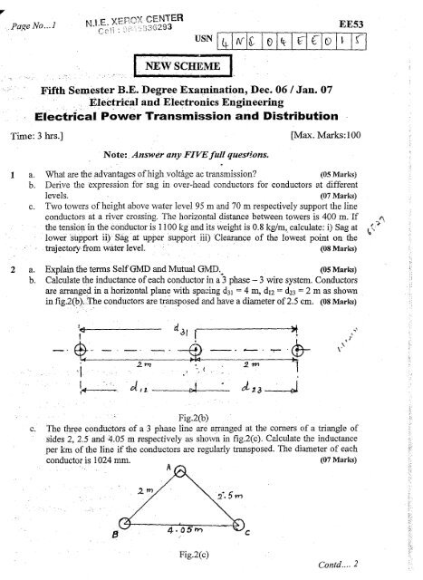
b. Calculate the inductance of each conductor in a '3 phase- 3 wire system. Conductors<br />
are arranged in a horizontal plan~ with spacing d31= 4 m, d12= d23= 2 m as shown<br />
in fig.2(b ).;~e conductors are transposed <strong>and</strong> have a diameter of 2.5 em. (08 Marks)<br />
1 )/f ~-? ,;.<br />
~ ...... -, -'~.~ ' --' -'.~ '\..!T"' ~ \). ..<br />
\ I • (<br />
" ..<br />
2. 'I'T/ " 2 m '~I<br />
~4 oi, Z. c:J.--.-~ d 1.3 . J<br />
Fig.2(b)<br />
c. The three conductors of a 3 phase line are m:ranged at the corners of a triangle of<br />
sides 2, 25 <strong>and</strong>·4.05 ill respectively as sho'\'lll in fig.2(c). Calculate the inductance<br />
per km of the line if the conductors are regularly transposed. The diameter of each<br />
conductor is 1024 mID. (07 Marks)<br />
8<br />
4·otiN')<br />
Fig.2(c)<br />
Contd .... 2
.4 -t'-.- .... l'"' ••.•.~<br />
EE53<br />
3 a. Obtain the capacitance of a 3 phase line with unsymmetrical spacing. Assume lines<br />
are transposed .•. (08 Marks)<br />
b. Determine the capacitance of <strong>and</strong> charging current per Ian when the transmission<br />
line as shown in fig.3(b) is operating at 132 kV. The conductor diameter is 0.8 em.<br />
(07 Marks)<br />
..<br />
,<br />
I·<br />
".1.m<br />
Fig3(b)<br />
c. A 3 phase 50 Hz, 66 kV overhead line conductor system the conductors are placed in<br />
a horizontal plane as shown in the fig.3(c). The conductor diameter is L25 em. lfthe<br />
line length is 100 km. Calculate i) Capacitance per phase ii) Charging current/phase<br />
assuming complete transposition of the line. (05 Marks)<br />
I<br />
-'
PaJ;eNo ...3<br />
N.tE. XEROX CENTER<br />
Cell : 98'E~S36293<br />
EE53<br />
6 a. State five advantages of usingunderground cables for power distribution. (05 Marks)<br />
b. Derive an expression for insulationresistapce of a cable. (07 Marks)<br />
c. A single core cable has a conductorof diameter 1.2 cm <strong>and</strong> its insulation thickness is<br />
1.6 cm. The specific resistance of the insulating material is 7.5 X 10⁸ Macm.<br />
Calculate the insulation resistanceper kilometer of the cable. If now this resistance<br />
is to be increased by 20% calculatethe thickness of the additional layer of insulation<br />
required. (08 Marks)<br />
7 a. What are the advantages <strong>and</strong> disadvantages of radial distribution system? (05 Marks)<br />
b. Four lines A, B, C <strong>and</strong> D are connected to a common point 0 as shown in fig.7(b).<br />
Resistance of AO, BO, CO <strong>and</strong> DO are respectively 1,2,3 <strong>and</strong> 4 Ohms both go <strong>and</strong><br />
return <strong>and</strong> feeding points A, B, C <strong>and</strong> D are maintained at 230, 250, 240 <strong>and</strong> 220 V<br />
respectively. Find the potential of commollpoint 0 assuming no load is tapped from<br />
there. (07 Marks)<br />
c<br />
Fig.7(b)<br />
c. Determine the critical disruptivevoltage <strong>and</strong> the critical visual disruptive voltage for<br />
a 3 phase, 50 Hz, 132kV line situated in a temperature of 30 degree centigrade <strong>and</strong><br />
at a barometric pressure of 74 em. The conductor diameter is 1.5 em while the<br />
equilateral spacing between the conductors is 2.75 m. The surface irregularity<br />
factors are 0.9 <strong>and</strong> 0.75 for the critical disruptive voltage <strong>and</strong> the critical visual<br />
disruptive voltage respectively. (08 Marks)<br />
8 Write short notes on any four of the following:<br />
a. Ferranti effect.<br />
b. Corona in transmission lines.<br />
c. Stringing chart.<br />
d. Grading of cables.<br />
e. Skin effect.<br />
'~I<br />
*****<br />
.. ~<br />
A<br />
B.<br />
(20 Marks)<br />
I<br />
I<br />
I<br />
I<br />
I<br />
I<br />
I<br />
I<br />
I<br />
I<br />
I<br />
I<br />
I<br />
I<br />
I<br />
I<br />
I<br />
I<br />
I<br />
I<br />
I<br />
I<br />
I<br />
I<br />
I<br />
I<br />
I<br />
I<br />
I