Wedge Bonding - CoorsTek
Wedge Bonding - CoorsTek
Wedge Bonding - CoorsTek

Create successful ePaper yourself
Turn your PDF publications into a flip-book with our unique Google optimized e-Paper software.
<strong>Wedge</strong> <strong>Bonding</strong><br />
<strong>Wedge</strong>-<strong>Wedge</strong> Ultrasonic <strong>Bonding</strong><br />
<strong>Wedge</strong>-wedge wire bonding is the oldest semiconductor<br />
assembly process dependent solely on acoustic energy. There<br />
are a few exceptions where thermal energy (heat) is combined<br />
to further improve the welding action.<br />
The dominant ultrasonic frequency has been for many years<br />
60kHz. It is even lower on some applications where larger<br />
diameter wire (>38µm) is used. This was until the early 1990’s<br />
when Japanese researchers, following the development and<br />
publications of Texas-based researchers, learned about the<br />
process improvements when higher ultrasonic frequencies<br />
(>60kHz) are used to bond gold wire to aluminum bond pads.<br />
Their investigation confirmed the improvements in weld reactivity<br />
(less open bond) and faster bond cycles. The major<br />
discovery was the fact that welding begins as soon as the wire<br />
contacts the surface to be bonded, creating a new welding<br />
pattern characterized by a series of parallel welding lines.<br />
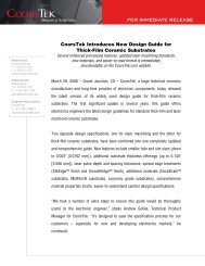
The new welding pattern does not follow the traditional low<br />
frequency pattern where the center of the bond is voided<br />
and surrounded by a welded ring. It has been published that<br />
during the welding process, lower ultrasonic frequencies<br />
begin utilizing some of the energy on wire deformation,<br />
followed by the actual welding process therefore the voided<br />
center.<br />
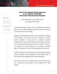
Higher frequencies have lower vibratory amplitude, but a<br />
much higher speed of vibration that allows a great deal of<br />
energy to concentrate at the interface of the bond. The lower<br />
mechanical amplitude as reported by the Japanese researcher<br />
and confirmed by the Texas-based researchers, produce lower<br />
deformation of the weld with reduced stresses providing a<br />
much larger cross-section area that reduces heal cracks, and<br />
improves bond pull values and overall weld strength.<br />
Figure 3 – High-frequency bond<br />
Figure 4 – Low-frequency bond<br />
Figure 1 – After C. Alfaro<br />
1992 – High Frequency<br />
Weld Pattern<br />
Figure 2 – After V.H. Winchell<br />
IEEE Proceedings 1978 – Low<br />
Frequency Weld Pattern<br />
Gaiser Products Group has taken this knowledge a step further<br />
by improving its materials and geometrical design to maximize<br />
acoustical efficiency so that any of our tools can either be used by<br />
standard low ultrasonic frequencies or by higher frequencies.<br />
We recommend you contact the factory for suggested information<br />
that might help improve tool set-up for those dealing<br />
with higher ultrasonic frequencies for the first time.<br />
60
<strong>Wedge</strong> <strong>Bonding</strong><br />
Small Wire <strong>Wedge</strong> <strong>Bonding</strong><br />
In wedge bonding, both aluminum and gold wire may be<br />
bonded. Historically, the disadvantages of wedge bonding<br />
vs. ball bonding have been speed (wires per second) and<br />
the need to rotate the work due to wedge bonders being<br />
unidirectional. Modern wedge bonders have made significant<br />
improvements in both areas. Semi-automatic and fully<br />
automatic wedge bonders have substantially increased the<br />
speed and versatility of the bonders. The “rotating head”<br />
wedge bonder has enabled 360° omnidirectional bonding,<br />
similar to ball bonding.<br />
With capillary ball bonding, time, force, ultrasonic energy,<br />
and heat are the primary components used to form a wire<br />
bond. With wedge bonding, however, both gold and<br />
aluminum wire may be bonded and no electronic flame<br />
off (EFO) is employed. The minimum requirement for gold<br />
wire wedge bonding is force to make a compression bond.<br />
For aluminum wire, both force and ultrasonic energy are<br />
necessary. Additionally, the component of heat may be<br />
available in the form of a heated stage or tool heat. <strong>Wedge</strong><br />
bonding is generally referred to as Ultrasonic <strong>Bonding</strong>.<br />
Ultrasonic <strong>Bonding</strong>: Ultrasonic energy is applied to the<br />
wedge tool through an ultrasonic transducer. The ultrasonic<br />
energy provides a mechanical scrubbing action which breaks<br />
through the surface oxide film and also generates frictional<br />
heat. Heat in the form of a heated tool or device may or may<br />
not be available.<br />
<strong>Wedge</strong> bonding is commonly used for aluminum wire<br />
chip-on-board (COB) applications, and gold wire for microwave<br />
and hybrid devices. In addition to gold wire, gold ribbon<br />
is becoming increasingly more popular for high frequency<br />
devices.<br />
Aluminum wire wedge bonding offers better cost benefits<br />
than that of gold wire. In general, wedge bonding allows<br />
bonds to be placed on small, narrow pads at fine pitches in<br />
a cost-effective manner.<br />
For microwave devices, wedge bonding offers a low, flat,<br />
short loop for maximum high-frequency electrical performance.<br />
Additionally, the wire loop shape may be controlled<br />
to a specific profile to “tune” a microwave device. Ribbon<br />
bonding makes use of the “skin-effect” observed in high- frequency<br />
telecommunications, microelectronics, and antenna<br />
technology.<br />
<strong>Wedge</strong> Design<br />
<strong>Wedge</strong> tip designs for many years have been limited to two<br />
types, the V-notch and the Maxiguide(or pocket type). The<br />
V-notch was developed first and had largely been obsoleted<br />
by the Maxiguide, which provides superior wire centering.<br />
The V-notch however, allows for a minimum “W” dimension<br />
for access into small recessed pads and a complete back<br />
radius (BR) which provides good 1st bond heels and 2nd<br />
bond tailing. Gaiser’s new patent pending MaxiBond design<br />
actually provides the positive aspects of both the V-notch and<br />
the Maxiguide in one new architecture, the MaxiBond.<br />
FR<br />
FR<br />
FR<br />
BL<br />
FL<br />
BL<br />
FL<br />
BL<br />
FL<br />
H<br />
H<br />
H<br />
BR<br />
BR<br />
T<br />
BR<br />
T<br />
T<br />
C<br />
C<br />
C<br />
WIRE FEED<br />
ANGLE<br />
Figure 5 – Cross-sectional view of a V-notch wedge with<br />
standard dimensions identified<br />
WIRE FEED<br />
ANGLE<br />
Figure 6 – Cross-sectional view of a Maxiguide wedge with<br />
standard dimensions identified<br />
WIRE FEED<br />
ANGLE<br />
Figure 7 – Cross-sectional view of a MaxiBond wedge with<br />
standard dimensions identified<br />
other<br />
die attach tab tools wedges capillaries<br />
<strong>CoorsTek</strong>, Inc.<br />
Gaiser Products Group<br />
4544 McGrath Street<br />
Ventura, CA 93003<br />
+1 805.644.5583 Tel<br />
+1 805.644.2013 Fax<br />
gaiser@coorstek.com<br />
www.gaisertool.com<br />
61
<strong>Wedge</strong> <strong>Bonding</strong><br />
The wedge shank is generally 1/16 inch diameter (1.58mm)<br />
with a shank flat secured by a set screw. Lengths are available<br />
in industry standard sizes up to 1.078 in./27.38mm and<br />
longer (by special order).<br />
In addition to being longer than a capillary, a significant<br />
advancement in wedge design has been the vertical feed,<br />
deep access wedge. Most wedge bonders feed wire into<br />
the tool at 30°, 38°, 45°, or 60° wire feed angles (relative<br />
to the horizon). Deep access, vertical feed wedge bonders<br />
are able to initially feed the wire vertically, like a capillary.<br />
The wire either passes vertically through a hollow (tubular<br />
construction) wedge, or through the transducer via a double<br />
shank flat design. Such vertical feed designs allow access<br />
into packages where a conventional 30° or 45° wire feed angle<br />
may have an interference problem.<br />
The Bond Foot (comprised of FR, BL, & BR)<br />
The “bond foot” is the portion of the wedge that makes the<br />
impression in the bonded wire. The entire feature is comprised<br />
of the front radius (FR), the bond length (BL), and the<br />
back radius (BR). These indiviual features have tolerances<br />
and therefore potential tolerance stack.<br />
To prevent the individual FR, BL, & BR tolerances from<br />
accumulating to form a too small or too large overall condition,<br />
Gaiser employs a control dimension called the foot<br />
length (FL) dimesion. The FL has an individual tolerance that<br />
prevents tolerance stack of the FR, BL, & BR.<br />
FLAT FACE TOOL<br />
25% of FR<br />
25% of BR<br />
VERTICAL<br />
FEED TOOL<br />
WIRE<br />
CLAMP<br />
FR<br />
BL<br />
BR<br />
60°<br />
FL<br />
PAD<br />
60°<br />
CONCAVE FACE TOOL<br />
PACKAGE<br />
25% of BR<br />
CAVITY<br />
DEPTH<br />
60°<br />
WIRE<br />
CLAMP<br />
FR<br />
BL<br />
BR<br />
FL<br />
VERTICAL<br />
FEED TOOL<br />
Figure 10 & 11 – Bond foot dimensions of a flat face and<br />
concave wedge<br />
PAD<br />
PACKAGE<br />
The FL dimension is measured from the FR to the theoretical<br />
intersection of the back radius angle and the plane of<br />
the bond foot, as shown above. The bond flat (BF) is the flat<br />
portion of the bond foot. On a flat face tool, the BF is the<br />
distance between the FR and the BR.<br />
Figure 8 & 9 – Conventional and deep access bonding<br />
62
<strong>Wedge</strong> <strong>Bonding</strong><br />
Bond Length (BL)<br />
The bond length (BL) for a flat-face wedge (see Figure 10)<br />
includes 25% of the BR, 25% of the FR, and the BF. For a<br />
concave wedge (see Figure 11), the BL begins where the<br />
concavity depth truncates the FR in the center of the BF<br />
and includes 25% of the BR.<br />
Choosing the BL is driven by the wire diameter and the size<br />
of the bond pad. Typical bond lengths are 1.5 to 2.5 times<br />
the wire diameter. Occasionally, the bond pad may be so<br />
small that it forces the use of a very small bond length. Bond<br />
lengths as small as 0.0010 in./25µm to 0.0007 in./18µm<br />
or 0.0005 in./13µm are used on small components and<br />
microwave devices.<br />
Bond Pad Size<br />
in. / µm<br />
Bond Length<br />
in. / µm<br />
0.0030<br />
/ 76<br />
0.0020 / 51<br />
0.0035<br />
/ 89 0.0020<br />
/ 51<br />
to 0.0022 / 56<br />
0.0040<br />
/ 102<br />
0.0025 / 64<br />
0.0050<br />
/ 127<br />
0.0030 / 76<br />
Front Radius (FR)<br />
The front radius (FR) provides the transition from the wire<br />
to the second bond. This transition, commonly referred to<br />
as the toe of the second bond, varies in size depending on<br />
the size of the FR. Most of the standard series of wedges,<br />
designed for aluminum wire, have an FR of 0.0010 in./25µm<br />
or larger to minimize second bond toe cracks. Gaiser<br />
designs the aluminum wire wedge FR to be the same size<br />
or larger than the wire diameter to be bonded.<br />
For gold wire applications, particularly when the wire diameters<br />
are 0.0010 in./25µm or smaller, the FR can be smaller<br />
than the wire diameter. A 0.0004 in./10µm FR is available<br />
in the microwave wedge series.<br />
Figure 13 – Gold wire lead bond formed with a wedge<br />
having a 0.0004 in./10µm FR<br />
Gaiser has specified the appropriate front radius values for<br />
various aluminum and gold wire wedge series that are available<br />
in our catalog for numerous applications. Modifications<br />
to the existing FR values is seldom necessary.<br />
BACK RADIUS (BR)<br />
The back radius (BR) has two functions:<br />
1.<br />
2.<br />
To provide the transition between the<br />
wire and the first bond or die bond<br />
To provide the area on the wedge where the<br />
wire will terminate on the lead bond<br />
die attach tab tools wedges capillaries<br />
Figure 12 – 2nd bond formed from wedge with an FR<br />
of 0.0010 in./25µm<br />
Figure 14 – Die bond made with part number 2130-2525-L<br />
with a standard BR. The length of wire not bonded on the<br />
left side is referred to as the tail. The tail length should<br />
not extend beyond the pad due to shorting problems. The<br />
standard BR helps provide for very consistent tailing.<br />
other<br />
<strong>CoorsTek</strong>, Inc.<br />
Gaiser Products Group<br />
4544 McGrath Street<br />
Ventura, CA 93003<br />
+1 805.644.5583 Tel<br />
+1 805.644.2013 Fax<br />
gaiser@coorstek.com<br />
www.gaisertool.com<br />
63
<strong>Wedge</strong> <strong>Bonding</strong><br />
Heel crack problems are more commonly associated with<br />
aluminum wire than with gold. They are also more frequent<br />
with 30° wire feed angle bonding than with steeper wire<br />
feed angles. This is due to the wire being worked more<br />
during looping. The wire starts out at a 30° angle, is flexed<br />
to 90° during the beginning of the loop, and is then returned<br />
to approximately 30° after the lead bond is made.<br />
Figure 17 – Bond made with part number 2130-2525-L-CBR,<br />
a maxiguide style wedge with a chamfered back radius<br />
A chamfer back radius (CBR) produces an angled transition<br />
as opposed to a radiused BR and helps to reduce heel cracks.<br />
As with the ELBR, the CBR is generally used with aluminum<br />
wire and may cause inconsistent tailing due to the stronger<br />
heel area.<br />
Figure 15 – Example of a minor heel crack<br />
The amount of heel cracking allowed depends on the quality<br />
standards of the end customer. In some cases, minor<br />
heel cracking is acceptable. BR shape and size may help<br />
to eliminate or reduce heel cracking.<br />
Figure 18 – Example of die bond made by the wedge<br />
part number 2160-2525-L-PBR-PFR, a polished front<br />
and back radius wedge<br />
Figure 16 – Bond made with part number 2131-2525-L,<br />
standard with elliptical back radius<br />
The elliptical back radius (ELBR) provides a stronger bond by<br />
increasing the amount of cross-sectional area of the heel but<br />
may cause inconsistent tailing as it creates a stronger heel<br />
area. This helps to reduce heel cracks often associated with<br />
standard wedges. The ELBR, generally used for aluminum<br />
wire, is standard for the 2131 series and available as an option<br />
on other Gaiser wedges.<br />
The polished back radius (PBR) and polished front radius<br />
(PFR) help reduce the amount of aluminum build-up on<br />
the bond foot but may reduce the ultrasonic energy transmission<br />
from the tool to the wire. These options produce<br />
a smooth appearance at the heel of the first bond and the<br />
toe of the second bond. The PBR may also help to reduce<br />
heel cracks.<br />
64
<strong>Wedge</strong> <strong>Bonding</strong><br />
wedges<br />
capillaries<br />
Figure 19 – Typical wedge lead bond. Tail length is minimal<br />
because the wire is terminated at this bond.<br />
Figure 21 – Example of a scratched wire<br />
Possible causes for a scratched wire:<br />
Figure 20 – Example of a smashed wedge bond<br />
A smashed bond may occur if there is insufficient tail<br />
length under the bond. This is often caused when the BR<br />
does not break the wire correctly. There must be enough<br />
wire under the FR and the BR to equalize the extrusion<br />
forces during bonding or overbonding and/or a weak heel<br />
may result.<br />
Hole Diameter (H)<br />
1.<br />
2.<br />
3.<br />
4.<br />
5.<br />
6.<br />
7.<br />
Wire is being fed into the hole of the<br />
wedge at an incorrect angle<br />
Wire is already scratched as it comes off the spool<br />
Wire clamp system not adjusted correctly<br />
Foreign material is present inside the<br />
wedge due to the bonding conditions<br />
<strong>Wedge</strong> has wire build-up and needs to be replaced<br />
Rough edge exists in the hole<br />
Hole is too small for the wire diameter<br />
Gaiser polishes the wedge wire feed hole as a standard<br />
manufacturing operation on all wedges.<br />
tab tools<br />
die attach<br />
The general design rule for the wedge hole diameter (H) is<br />
that the hole size should be 1.5-2 times the wire diameter.<br />
A tighter wire to hole size relationship will improve bond<br />
placement accuracy. If the hole is too small, wire scratch<br />
may result.<br />
Polish<br />
Polish<br />
Figure 22 – Hole polish detail of a 30° wire feed angle wedge<br />
other<br />
<strong>CoorsTek</strong>, Inc.<br />
Gaiser Products Group<br />
4544 McGrath Street<br />
Ventura, CA 93003<br />
+1 805.644.5583 Tel<br />
+1 805.644.2013 Fax<br />
gaiser@coorstek.com<br />
www.gaisertool.com<br />
65
Table-Tear & Clamp-Tear<br />
<strong>Wedge</strong> <strong>Bonding</strong><br />
Polish<br />
Exit Hole<br />
Polish<br />
Figure 23 – Hole polish and exit hole relief of 60° wire feed<br />
angle wedge<br />
Also available, and primarily used in fine pitch applications,<br />
is an oval hole design. The oval hole provides the lateral (side<br />
to side) bond placement accuracy of a smaller hole relative to<br />
the wire diameter while maintaining the wire feed and looping<br />
characteristics of a larger hole diameter.<br />
Hole<br />
Height<br />
Figure 24 – Oval Hole design<br />
Hole<br />
Width<br />
Figure 25 – Table-tear bond - The clamp is closed shortly<br />
after the second bond. The tool then moves upward<br />
and back to break the tail. Note: Nick in wire caused<br />
by BR during termination.<br />
There are two methods used to terminate the wire after the<br />
second bond. These methods are bonding machine dependent<br />
and are commonly called, “table-tear” and “clamp-tear.”<br />
Most deep access bonders and some conventional bonders<br />
utilize the table-tear method.<br />
The clamp-tear method is the standard method of termination<br />
for conventional bonding. In this method, the clamp remains<br />
open during completion of the lead bond. While the wedge is<br />
still on the wire, the clamp closes and pulls back away from<br />
the wedge. This motion causes the wire to terminate at the<br />
BR. The wedge then rises and the clamp system moves<br />
down. This forces the wire to feed out leaving the tail under<br />
the bond foot for the next bond.<br />
One benefit of the clamp-tear method is that the bond is not<br />
stressed (lifted) when terminating the wire. Another benefit<br />
is that there is no nick in the wire above the heel which may<br />
be present when using the table-tear method. The biggest<br />
disadvantage of the clamp-tear method is that the clamp<br />
system can interfere with the package wall or other devices<br />
thereby restricting deep-access use.<br />
66
<strong>Wedge</strong>s<br />
<strong>Wedge</strong> <strong>Bonding</strong> Process<br />
1.<br />
The bonding process begins<br />
with a threaded wedge.<br />
2.<br />
Force and Ultrasonic Energy are<br />
applied to form the 1st Bond.<br />
capillaries<br />
3. The Looping Sequence<br />
4. Force and Ultrasonic Energy are<br />
applied to form the 2nd Bond.<br />
wedges<br />
Tail Length<br />
tab tools<br />
5.<br />
The wedge rises before the<br />
tear method is engaged.<br />
6.<br />
The Clamp-Tear or Table-Tear<br />
methods are used to break the<br />
wire and the cycle begins again.<br />
2) Heel Break<br />
(Influenced By BR)<br />
3) Mid-Span Break (Ideal)<br />
4) 2nd Bond Break<br />
(Influenced By FR)<br />
die attach<br />
1) Lifted Bond<br />
5) Lifted Bond<br />
Preferred Failure Modes<br />
• Mid-Span Break (Bond Strength exceeds<br />
Wire Tensile Strength)<br />
• 2nd Bond Break<br />
• Heel Break<br />
Undesirable Failure Modes<br />
• Low-Strength Heel Breaks<br />
• Lifted Bond<br />
other<br />
<strong>CoorsTek</strong>, Inc.<br />
Gaiser Products Group<br />
4544 McGrath Street<br />
Ventura, CA 93003<br />
+1 805.644.5583 Tel<br />
+1 805.644.2013 Fax<br />
gaiser@coorstek.com<br />
www.gaisertool.com<br />
67
<strong>Wedge</strong> <strong>Bonding</strong><br />
Materials & Tip Configurations<br />
The wire material (gold or aluminum) being bonded generally<br />
determines the material specified for the wedge and the<br />
bond foot configuration. Tungsten Carbide (WC) combined<br />
with a concave bond foot is the industry standard for small<br />
aluminum wire. For gold wire, Titanium Carbide (TiC) or a<br />
“Cermet” material combined with a flat face and possibly a<br />
cross groove, are the standards.<br />
F<br />
INWARD<br />
FORCE<br />
The cross groove feature also provides a mechanical<br />
coupling for ultrasonic energy transmission between the<br />
wedge and the wire. As the wire is extruded up into the cross<br />
groove, it is “gripped” during bonding. A bond length of<br />
at least 0.0015 in./38µm is necessary to allow for enough<br />
space for a cross groove. The cross groove and cermet<br />
combination have proven to be highly effective for gold wire<br />
bonding.<br />
In addition to the traditional gold color cermet (CER),<br />
Gaiser has introduced black cermet. Black cermet (BKCER)<br />
exhibits improved dimensional stability and smoother<br />
holes for reduced wire scratch while still providing a rough,<br />
aggressive finish on the bond foot. When compared to a<br />
competitor’s standard gold cermet, Gaiser black cermet has<br />
demonstrated improved pull strengths. Additionally, the<br />
visual contrast between the black cermet and gold wire is<br />
helpful to operators during set-up and operation.<br />
F 1<br />
F 2<br />
F 1<br />
< F 2<br />
Figure 26 – Inward force created by concave foot<br />
F<br />
Figure 28 – Cermet-tipped, cross groove wedge<br />
F 1<br />
F 2<br />
F 1<br />
= F 2<br />
The photos above and below are the same wedge part<br />
number. The top is a cermet material and the bottom is a<br />
tungsten carbide material.<br />
Figure 27 – Outward bond extrusion with flat face<br />
Cermet is a ceramic-metal alloy that exhibits a very rough<br />
and aggressive surface finish. This rough finish provides a<br />
mechanical coupling with the wire and effectively transmits<br />
ultrasonic energy at reduced power settings. Additionally,<br />
cermet material generally provides a longer tool life than<br />
carbide materials.<br />
Figure 29 – Tungsten carbide (WC), cross groove wedge<br />
68
<strong>Wedge</strong> <strong>Bonding</strong><br />
capillaries<br />
Figure 30 – Bond formed with a cermet-tipped wedge<br />
Gaiser wedges typically default to tungsten carbide (WC)<br />
material and a concave face which is best suited for aluminum<br />
wire. Titanium carbide (TiC), cermet (CER), a flat face<br />
(F), and a cross groove (CG) are all options that must be<br />
specified in the part number and are generally affiliated with<br />
gold wire bonding. The 2MXX and 2GXX series wedges are<br />
standard with flat faces (both) and cross grooves (2GXX only)<br />
as they are designed for small geometry microwave and/or<br />
gold wire applications.<br />
Figure 35 – Typical IC wedge bonded aluminum wire<br />
wedges<br />
Figure 36, 37, & 38 – Comparison of the wire being<br />
guided through V-notch (left) and Maxiguide (middle)<br />
and MaxiBond (right) style wedges.<br />
tab tools<br />
Chip On Board <strong>Bonding</strong> (COB)<br />
Figure 31 & 32 – Gaiser cermet wedges (left) exhibit a<br />
near-zero thickness material junction. The competitor’s<br />
wedge (right) exhibits a large braze/solder joint.<br />
Figure 33 & 34 – Gaiser cermet wedges (left) are polished at<br />
the countersink exit. The competitor’s cermet wedge (right)<br />
exhibits an “as EDM’ed” finish and coarse grinding marks.<br />
The majority of chip on board (COB) products require a<br />
30° wire feed. Gaiser 2130 series wedge has gained the<br />
most acceptance in the industry for these applications by<br />
offering low cost, accurate wire placement, and consistently<br />
small tails.<br />
For standard applications using 0.0010 in./25µm to<br />
0.00125 in./32µm diameter aluminum wire, Gaiser part<br />
number 2130-2025-L has proven to be an effective, easy<br />
to tune, and long lasting wedge. At 100µm pitch, the<br />
2130-2020-L-W=003 has become a commonly used<br />
part number. For below 100µm pitch, the 2130-2020-<br />
L-DSR(004x010)-ELBR-W=003 has gained popularity.<br />
This wedge features the double side relief (DSR) and a<br />
narrower foot width (W) for the close bond pad pitch<br />
requirements. The elliptical back radius (ELBR) feature<br />
is also added to this wedge to aid in directing the wire<br />
to the center of the bond pad for superior wire placement.<br />
die attach<br />
other<br />
<strong>CoorsTek</strong>, Inc.<br />
Gaiser Products Group<br />
4544 McGrath Street<br />
Ventura, CA 93003<br />
+1 805.644.5583 Tel<br />
+1 805.644.2013 Fax<br />
gaiser@coorstek.com<br />
www.gaisertool.com<br />
69
Fine-Pitch <strong>Wedge</strong> <strong>Bonding</strong><br />
Important Elements for Fine-Pitch Applications<br />
FRONT VIEW<br />
SIDE VIEW<br />
WIRE DIA.<br />
DSR WIDTH<br />
CLEARANCE<br />
CRITICAL<br />
LOOP HEIGHT<br />
ADJACENT TO<br />
WEDGE<br />
LOOP HEIGHT<br />
MAXIMUM<br />
PAD<br />
WIDTH<br />
PAD<br />
PITCH<br />
PAD<br />
LENGTH<br />
Important Elements for Determining the Proper Tools in Fine-Pitch <strong>Wedge</strong> <strong>Bonding</strong> Applications<br />
Bond Pad Pitch: The distance between the centers of the bond pads.<br />
Bond Pad Width: Affects the selection of the tool “W” dimension.<br />
Bond Pad Length: Affects the selection of the tool Bond Length (BL).<br />
Loop Height: The most important height is the critical loop height directly adjacent to the side of the wedge.<br />
Clearance: This is determined by bonder accuracy, pad pitch, tool selection, and customer preference. The most common<br />
minimum clearance is 0.0005 in./13µm.<br />
CLEARANCE = PITCH - DSR WIDTH - WIRE DIAMETER<br />
2<br />
70
Fine-Pitch <strong>Wedge</strong> <strong>Bonding</strong><br />
Fine-Pitch <strong>Wedge</strong> <strong>Bonding</strong><br />
The key to achieving fine-pitch wedge bonding is to provide<br />
clearance between the already bonded wire’s adjacent critical<br />
loop height and the wedge itself as it performs the next bond.<br />
Reducing the tip width (the “W” dimension) will allow bonding<br />
at a smaller pitch with a given part number. However, to<br />
truly achieve very fine pitch wedge bonding, a double side<br />
relief (DSR) is necessary.<br />
Pitch<br />
µm<br />
General Fine-Pitch <strong>Wedge</strong> <strong>Bonding</strong> Guide<br />
30° to 45° Wire Feed Angles<br />
Wire Diameter<br />
in. / µm<br />
DSR<br />
150<br />
0.00125<br />
/ 32<br />
N / A 0.004+<br />
125<br />
0.00125<br />
/ 32<br />
N/<br />
A 0.004<br />
100<br />
0.00125 / 32<br />
N/A to<br />
(0.005x0.010)<br />
0.003<br />
80<br />
0.00125<br />
/ 32<br />
(0.004x0.010) 0.003<br />
60<br />
0.00125<br />
/ 32<br />
(0.003x0.008) 0.0025<br />
50<br />
0.0010<br />
/ 25<br />
Special Design<br />
The previous page shows the relationship between the bond<br />
pad pitch, the bond pad size (sometimes called the bond<br />
pad opening), the wedge tool with a DSR, the wire (both the<br />
critical adjacent and maximum loop heights), and the clearance.<br />
The necessary clearance is somewhat arbitrary with<br />
the bonder accuracy playing a large role in how small the<br />
clearance may be – minimal clearance is desirable because<br />
then a maximum DSR width can be used. A maximum DSR<br />
width provides the strongest wedge tool and maintains better<br />
ultrasonic energy transmission characteristics as well as a<br />
larger countersink for easier threading.<br />
Fine-Pitch <strong>Wedge</strong> -<br />
Hole Size (H)<br />
N/A = not applicable, unnecessary<br />
As stated earlier in the wedge bonding section of this<br />
catalog, the general design rule is that the hole size<br />
should be 1.5-2 times the wire diameter. Fine-pitch<br />
wedges may require a tighter hole to wire relationship,<br />
such as 1.4-1.8 times the wire diameter. Additionally, the<br />
oval hole option may be beneficial in fine-pitch bonding<br />
for a very tight lateral (side to side) relationship for<br />
bond placement while still maintaining low wire drag<br />
for looping and bonder speed (wires per second).<br />
W<br />
Fine-Pitch <strong>Wedge</strong> -<br />
Bond Length (BL)<br />
The general design rule for bond length (BL) is 2 times the<br />
wire diameter. Fine-pitch wedges, however, may require<br />
1.5-1.8 times the wire diameter due to reduced bond pad<br />
openings. The expected deformed bonded wire width is<br />
1.3-1.8 times the original wire diameter. Longer bond<br />
lengths tend to produce more narrow bond widths.<br />
Fine-Pitch <strong>Wedge</strong> -<br />
Part Number Guide<br />
FRONT VIEW<br />
General Fine-Pitch <strong>Wedge</strong> Part Number Guide<br />
2130, 2131, 2138, 2145-(H & BL)-"Options"<br />
Pitch<br />
µm<br />
APEX OF<br />
LOOP<br />
Part Number Guide<br />
150<br />
21XX-(H & BL)<br />
125<br />
21XX-(H & BL)<br />
100<br />
21XX-(H & BL), W=003,<br />
Possible DSR(005x010)<br />
80<br />
21XX-(H & BL), DSR(004x010), W=003<br />
60<br />
21XX-(H & BL), DSR(003x008), W=0025<br />
50 and<br />
below<br />
Special Design, Consult Factory<br />
SIDE VIEW<br />
Figure 39 – Typical wire loop profile after the first wire is<br />
bonded. Note that the already bonded wire does not collide<br />
with the side of the wedge because the apex of the loop<br />
is behind the wedge. Since the majority of the looping<br />
profiles are at a low angle, the primary fine-pitch problem<br />
is clearing the adjacent bond and the critical loop height<br />
(see adjacent page for critical loop height).<br />
other<br />
die attach tab tools wedges capillaries<br />
<strong>CoorsTek</strong>, Inc.<br />
Gaiser Products Group<br />
4544 McGrath Street<br />
Ventura, CA 93003<br />
+1 805.644.5583 Tel<br />
+1 805.644.2013 Fax<br />
gaiser@coorstek.com<br />
www.gaisertool.com<br />
71
Fine-Pitch <strong>Wedge</strong> <strong>Bonding</strong><br />
Figure 40 – Drawing showing the double side relief (DSR)<br />
Figure 42 – Drawing showing the advantage of a 45° side<br />
chamfer<br />
The double side relief (DSR) option is designed to provide<br />
the clearance necessary when bonding down inside a cavity,<br />
between an obstruction, package wall, or other device.<br />
The DSR modification must be specified in the part number<br />
as “DSR (Width x Height).”<br />
The 45° side chamfer modification is beneficial in fine pitch<br />
bonding because it allows the wedge to maintain most of<br />
its mass resulting in efficient transfer of ultrasonic energy.<br />
It allows the use of a larger “W” dimension while still<br />
maintaining clearance to the adjacent bond. The 45° side<br />
chamfer can be added to the maxiguide style wedge<br />
without weakening the guiding slot walls. Specify this<br />
option in the part number as “45SC(W=specify)”.<br />
Figure 41 – Photo of tool with a double side relief<br />
Note: Tool also has a 45° side chamfer modification<br />
Figure 43 – Photo of a 45° side chamfer modification<br />
Also see MaxiBond Series pages 80 and 81<br />
72
Large Wire <strong>Bonding</strong><br />
Large Wire <strong>Wedge</strong> <strong>Bonding</strong><br />
“Large wire” wedge bonding generally refers to wire diameters<br />
of 0.004 in./100µm to 0.030 in./760µm with 0.005/127µm to<br />
0.015 in./380µm being the most common. Because the range<br />
for “small wire” is usually defined from 0.0007 in./18µm to<br />
0.002 in./50µm, this leaves 0.003 in./76µm wire in the middle.<br />
This is most likely the reason for so few 0.003 in./76µm wire<br />
applications. Virtually all large wire wedge applications utilize<br />
aluminum wire for cost reasons with the exception of certain<br />
“exotic” applications.<br />
Most large wire wedge bonders use a single groove wedge<br />
tool and a separate cutter blade while some bonders utilize<br />
a wire feed hole at the tip with the same configuration as a<br />
small wire wedge. A patented design by Orthodyne Electronics<br />
incorporates a cutter blade at the tip in a groove parallel to the<br />
groove used for making the wire bond (see Figure 45).<br />
Figure 46 – Drawing shows a typical U-groove style wedge<br />
capillaries<br />
wedges<br />
Figure 47 – Bonds made with a U -groove wedge may exhibit<br />
surrounding wire smash‐out. Also called “wings” or “ears”<br />
tab tools<br />
Figure 44 – Wire feed hole style large wire wedge<br />
Figure 48 – Drawing shows a typical V-groove style wedge<br />
die attach<br />
Figure 45 – Patented Orthodyne cut-off ridge design<br />
Figure 49 – Bonds made with a V-groove wedge exhibit<br />
minimum smash-out<br />
other<br />
<strong>CoorsTek</strong>, Inc.<br />
Gaiser Products Group<br />
4544 McGrath Street<br />
Ventura, CA 93003<br />
+1 805.644.5583 Tel<br />
+1 805.644.2013 Fax<br />
gaiser@coorstek.com<br />
www.gaisertool.com<br />
73
<strong>Wedge</strong> <strong>Bonding</strong><br />
Ribbon <strong>Wedge</strong> <strong>Bonding</strong><br />
Ribbon bonding is accomplished using a wedge-style tool<br />
that is designed essentially the same as a small wire wedge<br />
except the wire feed hole is a horizontal slot, not a round<br />
hole. This is needed to facilitate the feeding of a flat ribbon<br />
as opposed to conventional wire. Many high-frequency<br />
devices utilize ribbon bonding due to the “skin affect” of<br />
a high-frequency signal.<br />
<strong>Wedge</strong> Finish<br />
All of the Gaiser wedges come standard with an EDM matte<br />
finish. The standard EDM matte finish is commonly used for<br />
both aluminum and gold wire.<br />
Gaiser offers ribbon bonding version of wedge tools for<br />
virtually all wire bonders, both standard and deep access.<br />
Ribbon wedges are available in all standard wedge materials<br />
for both gold and aluminum ribbon (WC, TiC, and cermet).<br />
Figure 52 – Standard EDM matte finish<br />
In some cases, the entire bond foot is polished (PBF) in<br />
an attempt to minimize build-up on the wedge. As the<br />
polishing of the bond foot inhibits good transfer of ultrasonic<br />
energy, the polished bond foot is not recommended,<br />
unless other options fail to provide the desired results. The<br />
PBF may also be called out if having shiny bonds instead of<br />
matte finish bonds is required.<br />
Figure 50 – Example of aluminum ribbon bonds.<br />
Note the cross groove impressions in the bonds.<br />
Figure 53 – Example of a polished bond foot<br />
Figure 51 – Device bonded with gold ribbon<br />
74
<strong>Wedge</strong> <strong>Bonding</strong><br />
Aluminum <strong>Wedge</strong> Cleaning<br />
ULTRASONIC<br />
CLEANER<br />
Aluminum build-up occurs on the bonding foot of the wedge<br />
after a period of usage. Polishing the FR and BR, using a fine<br />
matte finish (FMF), or changing styles of wedge can aid in<br />
reducing the quickness of this build-up.<br />
Eventually, the aluminum deposits left on the surfaces of the<br />
wedge will require the wedge to be cleaned or replaced.<br />
20% NaOH<br />
SOLUTION<br />
BEAKER<br />
WEDGES<br />
PLASTIC BLOCK<br />
WITH HOLES<br />
capillaries<br />
Figure 56 – Aluminum cleaning set-up<br />
Figure 54 – MaxiGuide wedge with aluminum build-up<br />
accumulated after 100,000 bonds.<br />
Aluminum can be etched away from the bond foot of the<br />
wedge by using a 20% by weight solution of sodium hydroxide<br />
(NaOH). An ultrasonic cleaner should be used, if available,<br />
to speed up the etching process. Using an ultrasonic cleaner,<br />
the process takes about 10 minutes. Without the aid of an<br />
ultrasonic cleaner, the process may take up to two hours. A<br />
plastic block with holes drilled to hold the wedges is necessary<br />
to keep the tool tips from vibrating together in the ultrasonic<br />
cleaner as shown above.<br />
After the wedges are removed from the solution of NaOH, they<br />
should be rinsed in deionized water and blown dry for at least<br />
two cycles. Each wedge cleaned should then be inspected for<br />
cleanliness and wear. For stubborn aluminum deposits, this<br />
process can be repeated. In addition to the above cleaning<br />
procedure, if the wedge has aluminum build-up in the hole, a<br />
piece of tungsten wire or an unplugging probe can be used. If<br />
a wire or probe is used, the NaOH cleaning procedure should<br />
be repeated. This will assure that no flakes of metal are lodged<br />
in the hole, countersink, or maxiguide slot area that could<br />
cause wire feeding problems or device contamination.<br />
die attach<br />
wedges<br />
tab tools<br />
Figure 55 – Slightly deformed bond surface caused by using<br />
a wedge with aluminum build-up. A similar appearance<br />
may be caused by a worn wedge.<br />
Figure 57 – The same MaxiGuide wedge as seen in Figure<br />
54 after the sodium hydroxide cleaning. Note the small<br />
amount of wear.<br />
other<br />
<strong>CoorsTek</strong>, Inc.<br />
Gaiser Products Group<br />
4544 McGrath Street<br />
Ventura, CA 93003<br />
+1 805.644.5583 Tel<br />
+1 805.644.2013 Fax<br />
gaiser@coorstek.com<br />
www.gaisertool.com<br />
75
<strong>Wedge</strong> Part Number System<br />
How To Order<br />
Example part Number:<br />
Aluminum Wire<br />
A. Series<br />
B. Wire Feed Angle*<br />
C. Hole Size<br />
D. Bond Length<br />
E. Tool Length<br />
2130-2025-L<br />
Example Part Number:<br />
Gold Wire<br />
2130-2025-L-CG-F-TiC<br />
F. Optional Cross Groove<br />
Optional Flat Face<br />
(standard on some series)<br />
G. Optional Material<br />
A. & B. Series & Wire Feed Angle:<br />
See the following catalog pages for various styles of wedges for aluminum and gold wire.<br />
*Except the 2131 series where the 31 designates a 38° wire feed angle wedge with an elliptical back radius.<br />
C. Hole Size:<br />
Specify based on wire size and wire feed angle.<br />
See the tables for each series for recommended wire diameters.<br />
XX = 0.00XX<br />
20 = 0.0020 in./51µm<br />
D. Bond Length:<br />
Specify based on bond pad size and wire diameter.<br />
XX = 0.00XX<br />
15 = 0.0015 in./38µm<br />
E. Tool Length:<br />
Specify based on bonder requirement. See following page for industry standard lengths.<br />
F. Options:<br />
Specify in alphabetical order in part number after the length designation.<br />
“-F” = Flat Face<br />
“-CG-F” = Cross Groove & Flat Face<br />
“-CC-CG” = Concave Face & Cross Groove<br />
“-LG” = Longitudinal Groove<br />
“-PBR” = Polished Back Radius**<br />
“-PFR” = Polished Front Radius**<br />
“-PBF” = Polished Front & Back Radius & Bond Length**<br />
“-PCS” = Polished Countersink<br />
“-V” = Vertical Back Grind<br />
“-10DBA” = 10° Back Angle<br />
“-20DBA” = 20° Back Angle<br />
“-CSF” = Concave Side Flats<br />
“-45SC(W=Specify)” = 45° Side Chamfers<br />
“-ELBR” = Elliptical Back Radius<br />
“-CBR(Specify)” = Chamfered Back Radius<br />
“-MOD C” = Maximized C Clearance<br />
“-180 REV” = 180° Reverse Shank<br />
**Not available with Cermet material option<br />
See the Modifications page for illustrations and more options.<br />
Some of the above features are standard on some series and do not need to be specified.<br />
G. Material:<br />
Tungsten Carbide: Recommended for Aluminum wire. Standard, do not specify in part number.<br />
Titanium Carbide: Recommended for Gold wire. Specify “-TiC” at the end of the part number.<br />
Cermet-Tipped: Recommended for Gold wire. Specify “-BKCER” at the end of the part number.<br />
We reserve the right to change the design or specification of any catalog item without notice. Such changes will be in the interest of improving design.<br />
76
<strong>Wedge</strong>s<br />
Shank Design & Lengths<br />
Standard 1/16 inch Diameter Shank Designs<br />
wedges<br />
capillaries<br />
SD = Shank Diameter<br />
Ø0.0624/1.58mm<br />
+0.0001/0.003mm<br />
-0.0002/0.005mm<br />
SDF = Shank Diameter Flat<br />
0.0460/1.17mm<br />
±0.0005/0.013mm<br />
20°<br />
Length Specified<br />
in Part Number<br />
0.437/11.1mm = "-S"<br />
0.625/15.88mm = "-625"<br />
0.750/19.05mm = "-3/4"<br />
0.828/21.03mm = "-L"<br />
1.000/25.4mm = "-1.0"<br />
1.078/27.38mm = "-1.078"<br />
±0.005/0.13mm<br />
10°<br />
10°<br />
tab tools<br />
10°<br />
W Dimension<br />
Standard<br />
10° Back Grind<br />
Shank<br />
T Dimension<br />
Optional<br />
Vertical Grind<br />
Shank<br />
0.040/1.02mm<br />
±0.005/0.13mm<br />
180° Reverse Shank*<br />
(Not available<br />
Vertical Feed Style Tools)<br />
die attach<br />
Note: Small wire wedge shank styles vary slightly based on intended use and wire bonder design.<br />
For other shank characteristics, if any, see the catalog page for each series.<br />
*Dias Bonder Models US1800A & US1900A and K&S Bonder Models #8060 & #8090<br />
Dimensions in inches unless otherwise specified.<br />
other<br />
<strong>CoorsTek</strong>, Inc.<br />
Gaiser Products Group<br />
4544 McGrath Street<br />
Ventura, CA 93003<br />
+1 805.644.5583 Tel<br />
+1 805.644.2013 Fax<br />
gaiser@coorstek.com<br />
www.gaisertool.com<br />
77
<strong>Wedge</strong>s<br />
Tip Modifications<br />
RADIUS<br />
Hole<br />
Width<br />
DSR H<br />
Hole<br />
Height<br />
TOOL W<br />
DSR W<br />
Optional Double Side Relief<br />
Specified in part number<br />
-DSR(“W”x“H”)<br />
Example:<br />
For a double side relief 0.004 inch wide x 0.010 inch high,<br />
specify “-DSR(004x010)”<br />
Optional Oval Hole<br />
Specified in part number<br />
Width x Height<br />
Example:<br />
For an oval hole 0.0015 inch wide x 0.0020 inch high,<br />
specify “15x20” for hole size in part number<br />
(e.g. 2145-15x2015-L-F-CER)<br />
30°<br />
(Optional)<br />
20°<br />
(Standard)<br />
R0.0005 R0.0005<br />
W<br />
0.0010<br />
0.0010<br />
Standard Standard<br />
Back Angle Back Angle<br />
(If Any) (If Any)<br />
Optional 30° W Angle<br />
Specified in part number<br />
-30DG<br />
Optional Cross Groove<br />
Specified in part number<br />
-CG<br />
Standard in some series<br />
Enhances the transfer of ultrasonic energy<br />
in situations of poor bondability<br />
Recommended for flat face gold wire tools<br />
Optional Vertical Back Grind<br />
Specified in part number<br />
-V<br />
Standard in some series<br />
The vertical back grind is 0.040 inch high<br />
78
<strong>Wedge</strong>s<br />
Tip Modifications<br />
45°<br />
45°<br />
capillaries<br />
0.0003<br />
0.0003<br />
Chamfered W<br />
Chamfered W<br />
W<br />
W<br />
Original W<br />
Original W<br />
Optional T<br />
Standard T<br />
Optional Concave Side Flats<br />
Specified in part number<br />
-CSF<br />
Optional 45° Side Chamfers<br />
Specified in part number<br />
-45SC(W=“Chamfered W”)<br />
Optional T Size<br />
Specified in part number<br />
-T=“Optional T”<br />
wedges<br />
For fine-pitch wire bonding<br />
Example part number:<br />
2145-2020-3/4-F-45SC(W=003)-TiC<br />
For a T=0.010 inch,<br />
specify “-T=010”<br />
tab tools<br />
DETAIL A<br />
Standard C<br />
Maximized C<br />
DETAIL A<br />
15°<br />
0.001<br />
die attach<br />
Optional Modified C Dimension<br />
Specified in part number<br />
Optional Chamfered Back Radius<br />
Specified in part number<br />
-MOD C<br />
-CBR<br />
For maximum rear clearance<br />
other<br />
Note: The CBR option defaults to 0.0010 in./25µm, CBR(001),<br />
unless otherwise specified. For other CBR sizes, specify<br />
CBR(0008), CBR(0012), etc.<br />
<strong>CoorsTek</strong>, Inc.<br />
Gaiser Products Group<br />
4544 McGrath Street<br />
Ventura, CA 93003<br />
+1 805.644.5583 Tel<br />
+1 805.644.2013 Fax<br />
gaiser@coorstek.com<br />
www.gaisertool.com<br />
79