Self-Acting Temperature Controls with 2-Port Valves - Filter
Self-Acting Temperature Controls with 2-Port Valves - Filter
Self-Acting Temperature Controls with 2-Port Valves - Filter

You also want an ePaper? Increase the reach of your titles
YUMPU automatically turns print PDFs into web optimized ePapers that Google loves.
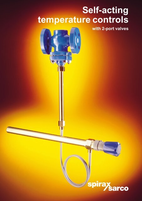
<strong>Self</strong>-acting<br />
temperature controls<br />
<strong>with</strong> 2-port valves
2<br />
<strong>Self</strong>-acting controls, the simplest and most<br />
reliable solution for controlling temperature<br />
Environment<br />
Some of the environments most likely to require self-acting temperature<br />
controls are:-<br />
• Explosive areas • Wet areas<br />
• External exposure • Dirty areas<br />
• Acid atmospheres • Power free locations<br />
• Shipboard • Underground<br />
Accuracy<br />
<strong>Self</strong>-acting controls give stable, modulating control <strong>with</strong>in close<br />
tolerances. On storage and constant load applications they will control<br />
at set value. On variable load applications they will normally operate<br />
<strong>with</strong>in a very narrow temperature band.<br />
Reliability<br />
Because our control systems operate through liquid expansion <strong>with</strong><br />
friction-free bellows, they have a long maintenance-free life <strong>with</strong><br />
repeatable performance.<br />
Easy to use<br />
'Set and forget' is the normal method of using self-acting controls. Even<br />
where temperature settings must vary, operators find them quick and<br />
simple to operate.<br />
Easy to install<br />
<strong>Self</strong>-acting temperature controls are a one-trade mechanical<br />
installation. The uncomplicated construction and small number of<br />
components makes them easy to understand so that installation<br />
is straightforward.<br />
Easy to commission<br />
Normally the operator or fitter sets the required temperature and<br />
that’s it. Some installations call for a few minutes re-setting otherwise,<br />
'set and forget'.<br />
Valve range<br />
For heating<br />
Body material Screwed Flanged<br />
Gunmetal DN15 - DN80 DN65 - DN80<br />
Cast iron DN15 - DN50 DN15 - DN50<br />
Cast carbon steel DN15 - DN50<br />
For cooling<br />
Body material Screwed Flanged<br />
Gunmetal DN15 - DN80 DN65 - DN80<br />
Cast iron DN15 - DN50 DN15 - DN50<br />
Cast carbon steel DN15 - DN50<br />
Gunmetal, cast iron and<br />
cast carbon steel valves<br />
for heating and cooling<br />
Bellows valve stem seals<br />
6 control system types<br />
controlling temperatures<br />
from -15�C to +170�C
Plastic coated copper<br />
capillaries <strong>with</strong> amoured<br />
covering. Standard lengths<br />
of 2 m, 4 m, 8 m and<br />
20 m all available<br />
from stock<br />
Flow<br />
Principles of operation<br />
A change in temperature at the sensor will cause<br />
the liquid filling to expand or contract. If the<br />
liquid expands it will apply a force on the thrust<br />
pin which, in turn, will cause the valve plug to<br />
move. As the liquid contracts the force on the<br />
valve plug reduces and a spring reverses its<br />
direction of travel.<br />
For heating applications the valves will be<br />
normally open and will close against a rise in<br />
temperature.<br />
For cooling applications the valves will be<br />
normally closed and will open against a rise in<br />
temperature.<br />
Plug<br />
Movement caused by<br />
temperature change at sensor<br />
User benefits<br />
Plug<br />
Thrust pin Thrust<br />
pin<br />
<strong>Temperature</strong> sensor<br />
Spring loaded piston<br />
mechanism for temperature<br />
adjustment and overload<br />
������� �������<br />
● Virtually maintenance free.<br />
● Intrinsically safe operation.<br />
● Simple to commission.<br />
● Free from electrical or<br />
pneumatic breakdown.<br />
● No expensive safety checks.<br />
Option of dial or<br />
tamper proof<br />
knob adjustment<br />
mechanism.<br />
● Low capital and installation cost -<br />
one-trade installation.<br />
● Accurate and reliable -<br />
for years of trouble free service.<br />
3
4<br />
Hot water storage<br />
Typical heating applications<br />
One of the most popular applications<br />
for self-acting control is hot water<br />
service where control valve (1)<br />
maintains a constant hot water<br />
temperature and control valve (2)<br />
provides protection against excess<br />
temperature*. The benefits of one-trade<br />
fix, value for money and 365 days per<br />
year reliability, make self-acting<br />
temperature controls a strong contender<br />
for this type of application.<br />
* See back page.<br />
2 1<br />
Plating tanks<br />
Where products are exposed to poor environmental<br />
conditions, noxious spillage or where the operator<br />
must re-set the control temperature <strong>with</strong><br />
changing batches, then self-acting controls<br />
provide close control coupled <strong>with</strong> safety,<br />
ease of use and robustness.
Boiler feedtanks<br />
An essential part of boiler feedwater conditioning is<br />
the need to drive out dissolved oxygen. This is an<br />
application which is basically simple and seldom,<br />
if ever, calls for anything but straightforward cost<br />
effective 'set and forget' self-acting controls.<br />
Sensing<br />
chamber<br />
Air vent<br />
Typical cooling application<br />
Control valve<br />
Sight glass<br />
Cooling water out<br />
Strainer<br />
Drain trap<br />
Air compressor cooling<br />
Air compressors call for modulating temperature<br />
control valves which will start up in the closed<br />
state and provide a minimum bleed through the<br />
jacketed air receiver for sensing purposes.<br />
As the water temperature in the sensing<br />
chamber increases the control valve will<br />
open to allow cold water into the<br />
jacketed air receiver.<br />
Cooling water in<br />
5
6<br />
�<br />
�<br />
�<br />
�<br />
�<br />
�<br />
�<br />
Valve selection<br />
How to select a system<br />
Is the application for heating or cooling?<br />
A heating application will require a valve that<br />
is normally open and will close <strong>with</strong> rising<br />
temperature. A cooling application will<br />
require a valve that is normally closed and<br />
will open <strong>with</strong> rising temperature.<br />
Is the valve to be used on steam or water?<br />
For steam the sizing table on page 7 is used<br />
and for water the table on page 8 is used.<br />
Determine the pressure upstream of the valve<br />
(P1 ) for normal running conditions.<br />
Determine the pressure downstream of the<br />
valve (P2 ) for normal running conditions.<br />
Determine the required flowrate of steam<br />
or water.<br />
Determine the size and basic type of valve using<br />
the sizing charts on pages 7 and 8. A sizing<br />
example is shown on each of these pages.<br />
������������������������������������������������������<br />
������������������������������������������������<br />
������������������������������������������<br />
�<br />
�<br />
��<br />
What body material is required?<br />
Pressure temperature limitations for each material<br />
(gunmetal, cast iron and cast carbon steel) are<br />
shown in table 3. Economics may also influence<br />
the choice of body material.<br />
What end connections are required -<br />
screwed or flanged? Choices are shown in tables 1<br />
and 2.<br />
Normally closed valves may have a bleed<br />
which allows a small flow to reach the sensor so<br />
that it can react to a temperature rise. This will be<br />
dependent on the application.<br />
What is the maximum differential pressure<br />
across the valve? In a heating application <strong>with</strong> a<br />
normally open valve a rise in temperature at the<br />
sensor will cause the valve to close. In order to<br />
ensure that the valve closes fully the sensor<br />
must be able to overcome the force generated on<br />
the valve plug by the maximum differential pressure<br />
across the valve (P ������ - P �����). This is often<br />
substantially greater than the normal running<br />
pressure drop across the valve. Similarly <strong>with</strong> a<br />
normally closed valve, the return spring must be able<br />
to close it against the maximum differential pressure.<br />
The maximum differential pressure for each valve is<br />
shown in tables 1 and 2 on pages 10 and 11. The<br />
maximum differential pressure of a valve may be<br />
increased by incorporating a balancing bellows,<br />
details of which are also indicated in tables 1 and 2.<br />
��<br />
��<br />
��<br />
��<br />
Control system selection<br />
�������������������������������������������<br />
������������������������������������������������<br />
�������������������������������������<br />
���������������������������<br />
From table 5 on page 13, select a temperature<br />
range which allows adjustment on both sides of the<br />
control point.<br />
Choose the configuration of the control system to<br />
suit the application.<br />
Choose the length of capillary tube.<br />
Choose any ancillaries (pockets, mounting brackets<br />
etc.) from page 14.<br />
� �<br />
Differential pressure<br />
������pressures for sizing charts are in bar g<br />
Typical order information<br />
������������������������������������<br />
�������������������<br />
�������������������������������������<br />
������������������������������<br />
��������������������������<br />
�����������������������<br />
� �
Inlet pressure bar g<br />
Steam flow kg / h<br />
1<br />
2<br />
3<br />
4<br />
5<br />
10<br />
20<br />
30<br />
40<br />
50<br />
100<br />
10<br />
20<br />
30<br />
40<br />
50<br />
100<br />
200<br />
300<br />
400<br />
500<br />
1 000<br />
2 000<br />
3 000<br />
4 000<br />
5 000<br />
10 000<br />
Differential pressure bar<br />
(P1 - P2 )<br />
Valve sizing for steam<br />
Sizing example for steam<br />
0.01<br />
0.04 0.03<br />
0.02<br />
0.3<br />
0.2<br />
0.05<br />
0.1<br />
0.4<br />
1<br />
0.5<br />
2<br />
Critical pressure drop<br />
3<br />
4<br />
Given: Pressure at valve inlet P1 = 6 bar g<br />
34 50 KA / KB / KC<br />
Pressure at valve outlet P2 = 4 bar g<br />
The required steam flowrate = 280 kg/h<br />
65 65 NS<br />
To size the valve:<br />
1 Determine the differential pressure across the valve P1 - P2 = 6 - 4 = 2 bar. 94 80 NS<br />
2 Enter the upper section of the chart <strong>with</strong> the inlet pressure (P1) at 6 bar g<br />
3<br />
and draw horizontal line to intersect the differential pressure (P1 - P2) line at 2 bar.<br />
From this intersection draw a vertical line downwards.<br />
Enter the lower section of the chart <strong>with</strong> the steam flowrate at 280 kg/h and draw a horizontal line to<br />
intersect the vertical line produced in step 2. From this intersection draw a line parallel to the diagonal<br />
lines in the direction of the valve selection box.<br />
4 From the valve selection boxes choose the valve <strong>with</strong> the higher Kvs value i.e. size DN20 'K' type valve.<br />
5<br />
10<br />
���<br />
����<br />
����� ��<br />
Heating<br />
����<br />
0.38 15 BX2 / BMF2 / BM2<br />
0.64 15 BX3 / BMF3 / BM3<br />
1.03 15 BX4 / BMF4 / BM4<br />
1.65 15 BX6 / BMF6 / BM6<br />
2.58 15 SB<br />
2.9 15 KA<br />
3.86 20 SB<br />
4.64 20 KA<br />
6.8 25 SB<br />
9.8 25 KA / KB<br />
16.48 32 KA / KB / KC<br />
16.48 40 KC<br />
23.7 40 KA / KB<br />
7
8<br />
������� � �<br />
500<br />
400<br />
300<br />
200<br />
100<br />
50<br />
40<br />
30<br />
20<br />
10<br />
5<br />
4<br />
3<br />
2<br />
1<br />
0.5<br />
0.4<br />
0.3<br />
0.2<br />
0.1<br />
200<br />
100<br />
������ � �<br />
50<br />
40<br />
30<br />
20<br />
10<br />
5<br />
4<br />
3<br />
2<br />
1<br />
0.5<br />
0.4<br />
0.3<br />
0.2<br />
0.1<br />
0.05<br />
0.04<br />
Valve sizing for water<br />
0.03<br />
0.01 0.02 0.05 0.1 0.5 1 5 10 40<br />
����������������������������������������������������<br />
Sizing example for water<br />
Given: Pressure at valve inlet P1 = 14 bar g<br />
Pressure at valve outlet P2 = 13 bar g<br />
The required water flowrate<br />
To size the valve:<br />
= 3 litres/second<br />
1 Determine the differential pressure across the valve P1 - P2 = 14 - 13 = 1 bar<br />
2 Enter the top chart (for heating applications) bottom chart (for cooling applications) <strong>with</strong> a flowrate<br />
of 3 litres/second and draw a horizontal line to intersect the differential pressure line at 1 bar.<br />
From this intersection draw a line parallel to the diagonal lines in the direction of the valve selection boxes.<br />
3 From the valve selection boxes choose the valve <strong>with</strong> the higher Kvs value i.e. size DN32 'K' type valve.<br />
� ��<br />
����<br />
����� ��<br />
Heating<br />
����<br />
94 80 NS<br />
65 65 NS<br />
34 50 KA / KB / KC<br />
23.7 40 KA / KB<br />
16.48 32 KA / KB<br />
16.48 40 KC<br />
9.8 25 KA / KB<br />
6.8 25 SB<br />
4.64 20 KA<br />
3.86 20 SB<br />
2.9 15 KA<br />
2.58 15 SB<br />
1.65 15 BX6 / BMF6 / BM6<br />
1.03 15 BX4 / BMF4 / BM4<br />
0.64 15 BX3 / BMF3 / BM3<br />
0.38 15 BX2 / BMF2 / BM2
500<br />
400<br />
300<br />
������� � �<br />
200<br />
100<br />
50<br />
40<br />
30<br />
20<br />
10<br />
5<br />
4<br />
3<br />
2<br />
1<br />
0.5<br />
0.4<br />
0.3<br />
0.2<br />
0.1<br />
200<br />
100<br />
50<br />
40<br />
������ � �<br />
30<br />
20<br />
10<br />
5<br />
4<br />
3<br />
2<br />
1<br />
0.5<br />
0.4<br />
0.3<br />
0.2<br />
0.1<br />
Valve sizing for water<br />
0.05<br />
0.04<br />
0.03<br />
0.01 0.02 0.05 0.1 0.5 1 5 10<br />
����������������������������������������������������<br />
40<br />
� ��<br />
����<br />
����� ��<br />
Cooling<br />
����<br />
94 80 NSRA<br />
65 65 NSRA<br />
34 50 KX / KY<br />
23.7 40 KX / KY<br />
16.48 32 KX / KY<br />
9.8 25 KX<br />
6.8 25 SBRA<br />
4.64 20 KX<br />
3.86 20 SBRA<br />
2.9 15 KX<br />
2.58 15 SBRA<br />
0.59 15<br />
BXRA / BMFRA<br />
/ BMRA<br />
9
10<br />
Valve selection data<br />
Table 1 - Normally open valves for heating applications<br />
Connections Control system options<br />
Valve model Size Screwed Flanged Bal- Kvs Maximum<br />
DN BSP NPT PN ANSI anced DP (bar)<br />
Gunmetal<br />
BX 2 15 • • 0.38 17.2 • • • • • •<br />
3 • • 0.64 17.2 • • • • • •<br />
4 • • 1.03 17.2 • • • • • •<br />
6 • • 1.65 17.2 • • • • • •<br />
SB 15 • • 2.58 17.2 • • • • • •<br />
20 • • 3.86 10.3 • • • • • •<br />
25 • • 6.80 6.8 • • • • • •<br />
KA51 25 • • 9.80 4.5 • • • • • •<br />
32 • • 16.48 3.0 • • • •<br />
40 • • 23.70 2.0 • • • •<br />
50 • • 34.00 1.5 • • • •<br />
KB51 25 • • • 9.80 10.0 • • • • • •<br />
Balanced by 32 • • • 16.48 9.0 • • • •<br />
phosphor 40 • • • 23.70 8.2 • • • •<br />
bronze bellows 50 • • • 34.00 6.9 • • • •<br />
KC51<br />
Balanced by<br />
stainless steel<br />
bellows<br />
40 • • • 16.48 16.0 • • • •<br />
50 • • • 34.00 13.8 • • • •<br />
NS double 65 • • 25 150 65.00 10.0 • • • •<br />
sealed valve 80 • • 25 150 94.00 10.0 • • • •<br />
Cast iron<br />
BMF 2 15 16 0.38 16.0 • • • • • •<br />
3 16 0.64 16.0 • • • • • •<br />
4 16 1.03 16.0 • • • • • •<br />
6 16 1.65 16.0 • • • • • •<br />
KA31 15 • • 2.90 13.0 • • • • • •<br />
20 • • 4.64 10.3 • • • • • •<br />
25 • • 9.80 4.5 • • • • • •<br />
32 • • 16.48 3.0 • • • •<br />
40 • • 23.70 2.0 • • • •<br />
50 • • 34.00 1.5 • • • •<br />
KA33 15 16 2.90 13.0 • • • • • •<br />
20 16 4.64 10.3 • • • • • •<br />
25 16 9.80 4.5 • • • • • •<br />
32 16 16.48 3.0 • • • •<br />
40 16 23.70 2.0 • • • •<br />
50 16 34.00 1.5 • • • •<br />
KB31 25 • • • 9.80 10.3 • • • • • •<br />
Balanced by 32 • • • 16.48 9.0 • • • •<br />
phosphor 40 • • • 23.70 8.2 • • • •<br />
bronze bellows 50 • • • 34.00 6.9 • • • •<br />
KB33 25 16 • 9.80 10.3 • • • • • •<br />
Balanced by 32 16 • 16.48 9.0 • • • •<br />
phosphor 40 16 • 23.70 8.2 • • • •<br />
bronze bellows 50 16 • 34.00 6.9 • • • •<br />
KC31<br />
Balanced by<br />
stainless steel<br />
40 16 • 16.48 13.0 • • • •<br />
bellows 50 16 • 34.00 13.0 • • • •<br />
For pressure temperature relationships please refer to operating charts on page 16.<br />
SA121<br />
SA122<br />
SA123<br />
SA128<br />
Type<br />
422<br />
SA423
Table 1 - Normally open valves for heating applications<br />
NS (DN65 - DN80 screwed)<br />
NS (DN65 - DN80 flanged)<br />
Connections Control system options<br />
Valve model Size Screwed Flanged Bal- Kvs Maximum<br />
DN BSP NPT PN ANSI anced DP (bar)<br />
Cast carbon steel<br />
BMF 2 15 25 300 0.38 17.2 · · · · · ·<br />
3 25 300 0.64 17.2 · · · · · ·<br />
4 25 300 1.03 17.2 · · · · · ·<br />
6 25 300 1.65 17.2 · · · · · ·<br />
KA43 15 40 300 2.90 17.0 · · · · · ·<br />
20 40 300 4.64 10.0 · · · · · ·<br />
25 40 300 9.80 4.5 · · · · · ·<br />
32 40 300 16.48 3.0 · · · ·<br />
40 40 300 23.70 2.0 · · · ·<br />
50 40 300 34.00 1.5 · · · ·<br />
KB43 25 40 300 · 9.80 10.0 · · · · · ·<br />
Balanced by 32 40 300 · 16.48 9.0 · · · ·<br />
phosphor 40 40 300 · 23.70 8.2 · · · ·<br />
bronze bellows 50 40 300 · 34.00 6.9 · · · ·<br />
KC43<br />
Balanced by<br />
stainless steel<br />
bellows<br />
32 40 300 · 16.48 16.0 · · · ·<br />
40 40 300 · 16.48 16.0 · · · ·<br />
50 40 300 · 34.00 13.8 · · · ·<br />
SB (DN15 - DN25 screwed)<br />
KA51 (DN25 screwed)<br />
KA31 (DN15 - DN25 screwed)<br />
KA33 (DN15 - DN25 flanged)<br />
KB33 (DN32 - DN50 flanged)<br />
KB43 (DN32 - DN50 flanged)<br />
KC43 (DN32 - DN50 flanged)<br />
SA121<br />
SA122<br />
SA123<br />
BX (DN15 screwed)<br />
BMF (DN15 flanged)<br />
BM (DN15 flanged)<br />
SA128<br />
SA423<br />
KA51 (DN32 - DN50 screwed)<br />
KA31 (DN32 - DN50 screwed)<br />
KA33 (DN32 - DN50 flanged)<br />
KA43 (DN15 - DN50 flanged)<br />
KB31 (DN25 screwed)<br />
KB51 (DN25 screwed)<br />
KB33 (DN25 flanged)<br />
KB51 (DN32 - DN50 screwed)<br />
KB31 (DN32 - DN50 screwed)<br />
KC51 (DN40 - DN50 screwed)<br />
KC31 (DN40 - DN50 screwed)<br />
Type<br />
422<br />
11
12<br />
Valve selection data<br />
Table 2 - Normally closed valves for cooling applications<br />
Connections Control system options<br />
Valve model Size Screwed Flanged Bal- Kvs Maximum<br />
DN BSP NPT PN ANSI anced DP (bar)<br />
Gunmetal<br />
BXRA 15 • • 0.59 10.3 • • • • • •<br />
SBRA 15 • • 2.58 12.0 • • • • • •<br />
Optional bleed 20 • • 3.86 7.0 • • • • • •<br />
available 25 • • 6.80 4.7 • • • • • •<br />
NSRA Double 65 • • 25 150 65.00 2.7 • • • •<br />
seated valve 80 • • 25 150 94.00 2.0 • • • •<br />
KX51 25 • • 9.80 3.5 • • • • • •<br />
Optional bleed 32 • • 16.48 2.3 • • • •<br />
available 40 • • 23.70 1.7 • • • •<br />
KY51<br />
Balanced by<br />
phosphor bronze<br />
bellows.<br />
Optional bleed<br />
available<br />
Cast iron<br />
50 • • 34.00 1.1 • • • •<br />
32 • • • 16.48 9.0 • • • •<br />
40 • • • 23.70 8.2 • • • •<br />
50 • • • 34.00 6.9 • • • •<br />
BMFRA 15 • • 0.59 10.3 • • • • • •<br />
KX31 15 • • 2.90 12.0 • • • • • •<br />
Optional bleed 20 • • 4.64 7.0 • • • • • •<br />
available 25 • • 9.80 3.5 • • • • • •<br />
32 • • 16.48 2.3 • • • •<br />
40 • • 23.70 1.7 • • • •<br />
50 • • 34.00 1.1 • • • •<br />
KX33 15 16 2.90 12.0 • • • • • •<br />
Optional bleed 20 16 4.64 7.0 • • • • • •<br />
available 25 16 9.80 3.5 • • • • • •<br />
32 16 16.48 2.3 • • • •<br />
40 16 23.70 1.7 • • • •<br />
KY31<br />
50 16 34.00 1.1 • • • •<br />
Balanced by<br />
phosphor<br />
32 • • • 16.48 9.0 • • • •<br />
bronze bellows.<br />
Optional bleed<br />
40 • • • 23.70 8.2 • • • •<br />
available.<br />
KY33<br />
50 • • • 34.00 6.9 • • • •<br />
Balanced by<br />
phosphor<br />
32 16 • 16.48 9.0 • • • •<br />
bronze bellows.<br />
Optional bleed<br />
40 16 • 23.70 8.2 • • • •<br />
available. 50 16 • 34.00 6.9 • • • •<br />
For pressure temperature relationships please refer to operating charts on page 16.<br />
SA121<br />
SA122<br />
SA123<br />
SA128<br />
Type<br />
422<br />
SA423
Table 2 - Normally closed valves for cooling applications<br />
Connections Control system options<br />
Valve model Size Screwed Flanged Bal- Kvs Maximum<br />
DN BSP NPT PN ANSI anced DP (bar)<br />
Cast carbon steel<br />
BMRA 15 25 0.59 10.3 • • • • • •<br />
KX43 15 40 2.90 12.0 • • • • • •<br />
Optional bleed 20 40 4.64 7.0 • • • • • •<br />
available 25 40 9.80 3.5 • • • • • •<br />
KY43<br />
32 40 16.48 2.3 • • • •<br />
40 40 23.70 1.7 • • • •<br />
50 40 34.00 1.1 • • • •<br />
Balanced by 32 40 • 16.48 9.0 • • • •<br />
phophor<br />
bronze bellows.<br />
Optional bleed<br />
40 40 • 23.70 8.2 • • • •<br />
available. 50 40 • 34.00 6.9 • • • •<br />
SBRA (DN15 - DN25 screwed)<br />
BXRA (DN15 screwed)<br />
BMFRA (DN15 flanged)<br />
BMRA (DN15 flanged)<br />
NSRA (DN65 - DN80 screwed)<br />
NSRA (DN65 - DN80 flanged)<br />
KX51 (DN25 screwed)<br />
KX31 (DN15 - DN25 screwed)<br />
KX33 (DN15 - DN25 flanged)<br />
SA121<br />
KX51 (DN32 - DN50 screwed)<br />
KX31 (DN32 - DN50 screwed)<br />
KX33 (DN32 - DN50 flanged)<br />
KX43 (DN15 - DN50 flanged)<br />
SA122<br />
SA123<br />
SA128<br />
Type<br />
422<br />
SA423<br />
KY51 (DN32 - DN50 screwed)<br />
KY31 (DN32 - DN50 screwed)<br />
KY33 (DN32 - DN50 screwed)<br />
KY43 (DN32 - DN50 flanged)<br />
13
14<br />
B<br />
C<br />
B<br />
B<br />
C<br />
B<br />
C<br />
B<br />
A<br />
��<br />
����<br />
A<br />
����<br />
����<br />
����<br />
����<br />
����<br />
����<br />
A<br />
���<br />
��<br />
�����<br />
����<br />
A<br />
����<br />
����<br />
����<br />
����<br />
����<br />
A<br />
����<br />
����<br />
����<br />
����<br />
Dimensions (approximate in mm)<br />
A<br />
��<br />
A<br />
��<br />
����<br />
���������<br />
A<br />
��<br />
����<br />
���������<br />
A<br />
����<br />
A<br />
����<br />
����<br />
����<br />
����<br />
C<br />
B<br />
C<br />
B<br />
C<br />
B<br />
C<br />
B<br />
C<br />
B<br />
Valve PN ANSI<br />
model BSP PN 25 / *150 Weight<br />
Size NPT 16 40 300 kg<br />
DN A A A A B C Scrd Flgd<br />
Cast iron<br />
BMF 15 130 87 3.6<br />
KA31 15 90 105 37 1.30<br />
20 104 105 37 1.60<br />
25 136 107 51 3.20<br />
32 144 110 51 5.10<br />
40 150 110 62 6.30<br />
50 180 110 71 7.80<br />
KA33 15 130 105 37 3.3<br />
20 150 105 37 4.3<br />
25 160 107 51 5.7<br />
32 180 110 51 8.8<br />
40 200 110 62 11.0<br />
50 230 110 71 13.0<br />
KB31 25 136 138 51 3.40<br />
32 144 152 51 5.70<br />
40 150 152 62 6.90<br />
50 180 152 71 8.80<br />
KB33 25 160 138 51 5.9<br />
32 180 152 51 9.1<br />
40 200 152 62 11.2<br />
50 230 152 71 13.4<br />
KC31 40 150 152 62 6.90<br />
50 180 187 71 9.10<br />
Valve PN ANSI<br />
model BSP PN 25 / *150 Weight<br />
Size NPT 16 40 300 kg<br />
DN A A A A B C Scrd Flgd<br />
Cast iron<br />
BMFRA15 130 87 3.6<br />
KX31 15 90 68 106 1.50<br />
20 104 68 106 1.80<br />
25 136 80 108 3.30<br />
32 144 80 112 5.30<br />
40 150 90 112 6.40<br />
50 180 100 112 7.90<br />
KX33 15 130 68 106 3.4<br />
20 150 68 106 4.4<br />
25 160 80 108 5.8<br />
32 180 80 112 8.9<br />
40 200 90 112 11.1<br />
50 230 100 112 13.1<br />
KY31 32 144 80 154 6.10<br />
40 150 90 154 7.30<br />
50 180 100 154 9.00<br />
KY33 32 180 80 154 9.2<br />
40 200 90 154 11.3<br />
50 230 100 154 13.5
Normally open valves for heating applications<br />
Valve PN ANSI<br />
model BSP PN 25 / *150 Weight<br />
Size NPT 16 40 300 kg<br />
DN A A A A B C Scrd Flgd<br />
Gunmetal<br />
BX 15 95 83 0.70<br />
SB 15 79 101 66 1.00<br />
20 105 101 66 1.30<br />
25 121 101 66 1.50<br />
KA51 25 136 107 51 3.96<br />
32 144 110 51 6.20<br />
40 150 110 62 7.52<br />
50 180 110 71 9.35<br />
KB51 25 136 138 51 4.17<br />
32 144 152 51 7.00<br />
40 150 152 62 8.32<br />
50 180 152 71 10.30<br />
KC51 40 150 152 62 8.32<br />
50 180 187 71 10.60<br />
NS 65 171 203 *203 150 150 8.10 17.2<br />
80 194 236 *236 160 160 13.60 22.7<br />
Valve PN ANSI<br />
model BSP PN 25 / *150 Weight<br />
Size NPT 16 40 300 kg<br />
DN A A A A B C Scrd Flgd<br />
Gunmetal<br />
BXRA 15 95 83 0.70<br />
SBRA 15 79 66 95 1.00<br />
20 105 66 95 1.30<br />
25 121 66 95 1.50<br />
NSRA 65 171 203 *203 150 150 8.10 17.2<br />
80 194 236 *236 160 160 13.60 22.7<br />
KX51 25 136 80 108 4.10<br />
32 144 80 112 6.32<br />
40 150 90 112 7.62<br />
50 180 100 112 9.50<br />
KY51 32 144 80 154 7.25<br />
40 150 90 154 8.57<br />
50 180 100 154 10.60<br />
Valve PN ANSI<br />
model BSP PN 25 / *150 Weight<br />
Size NPT 16 40 300 kg<br />
DN A A A A B C Scrd Flgd<br />
Cast carbon steel<br />
BM 15 130 127 87 3.6<br />
KA43 15 130 130 105 4.3<br />
20 150 150 105 6.3<br />
25 160 162 105 8.0<br />
32 180 180 110 8.7<br />
40 200 202 110 9.7<br />
50 230 232 110 14.6<br />
KB43 25 160 162 138 8.2<br />
32 180 180 152 9.1<br />
40 200 202 152 10.1<br />
50 230 232 152 15.0<br />
KC43 32 180 180 152 9.1<br />
40 200 202 152 10.1<br />
50 230 232 187 15.3<br />
Normally closed valves for cooling applications<br />
Valve PN ANSI<br />
model BSP PN 25 / *150 Weight<br />
Size NPT 16 40 300 kg<br />
DN A A A A B C Scrd Flgd<br />
Cast carbon steel<br />
BMRA 15 130 127 87 3.6<br />
KX43 15 130 130 68 106 4.4<br />
20 150 150 68 106 6.4<br />
25 160 162 80 108 8.1<br />
32 180 180 80 112 8.8<br />
40 200 202 90 112 9.8<br />
50 230 232 100 112 14.7<br />
KY43 32 180 180 80 154 9.2<br />
40 200 202 90 154 10.2<br />
50 230 232 100 154 15.1<br />
15
16<br />
<strong>Temperature</strong> °C<br />
<strong>Temperature</strong> °C<br />
<strong>Temperature</strong> °C<br />
260<br />
232<br />
200<br />
100<br />
300<br />
232<br />
200<br />
100<br />
0<br />
0 5 10 15 20 25<br />
Cast iron operating chart<br />
220<br />
200<br />
150<br />
100<br />
50<br />
Steam saturation curve<br />
0<br />
0 2 4 6 8 10 12 14 16<br />
0 0 10 20 30 40<br />
Gunmetal Cast iron Cast carbon steel<br />
Body design conditions PN25 PN16 PN25 PN40<br />
Maximum design temperature 260°C 220°C 300°C 300°C<br />
Maximum cold hydraulic test 38 bar g 24 bar g 38 bar g 60 bar g<br />
Gunmetal operating chart<br />
When valve is operating <strong>with</strong> spacer<br />
Cast carbon steel operating chart<br />
Limiting conditions<br />
Steam saturation curve<br />
When valve is operating <strong>with</strong> spacer<br />
(KA43 and KC43 only)<br />
Steam saturation curve<br />
Pressure bar g<br />
Pressure bar g<br />
Pressure bar g<br />
The product must not be used in this area<br />
Note: KB51 and KY51 maximum temperature 232°C<br />
The product must not be used in this area<br />
The product must not be used in this area<br />
Note: KB43 and KY43 maximum temperature 232°C
Control system selection<br />
The control systems are available in four configurations as shown below.<br />
Each type is available <strong>with</strong> either a dial or knob type temperature adjustment except the Type 422.<br />
Dimensions approximate in mm<br />
Actuator<br />
SA121, SA128<br />
271<br />
271<br />
Setting knob<br />
Capillary<br />
185<br />
Actuator<br />
SA123, SA423<br />
Capillary<br />
Setting knob<br />
Capillary<br />
270<br />
310 (SA121)<br />
178 (SA128)<br />
Sensor<br />
248<br />
Sensor<br />
25<br />
25<br />
415<br />
Actuator<br />
SA122<br />
395<br />
Specifications<br />
Setting knob<br />
Capillary<br />
Actuator<br />
Type 422<br />
Capillary<br />
Setting dial<br />
���� ����� ����������� �������������������������� ��������<br />
326<br />
Sensor<br />
240<br />
Sensor<br />
������ ��������<br />
* Longer lengths up to 9.6 m are available to special order<br />
17<br />
25<br />
�� ������������������<br />
1 -15 to 50�C<br />
SA121 2 40 to 105�C 55�C over set value to max. 190�C Brass 2.0 2, 4, 8 and 20<br />
3 95 to 160�C<br />
SA122<br />
1<br />
2<br />
-20 to 120�C<br />
40 to 170�C<br />
55�C over set value Brass 1.8 2, 4, 8, and 20<br />
1 -15 to 50�C<br />
SA123 2 40 to 105�C 55�C over set value Brass 2.5 2, 4, 8, and 20<br />
3 95 to 160�C<br />
SA128<br />
1 -20 to 110�C<br />
2 40 to 170�C<br />
55�C over set value to max. 190�C Brass 1.8 2, 4, 8, and 20<br />
C 25 to 60�C<br />
Type 422 D 50 to 85�C 55�C over set value Stainless 1.4 2.4 or 4.8 *<br />
E 70 to 105�C steel<br />
1 -15 to 50�C Stainless<br />
SA423 2 40 to 105�C 55�C over set value steel sensor 2.5 2, 4, 8, and 20<br />
3 95 to 160�C remainder brass<br />
17
18<br />
�"<br />
Control system ancillaries<br />
1"<br />
Twin<br />
sensor<br />
adaptor<br />
����������������<br />
�"<br />
1"<br />
Mild steel pocket · · · ·<br />
longer pocket option *<br />
· ·<br />
Stainless steel pocket · · · · ·<br />
longer pocket option *<br />
· · ·<br />
Copper pocket · · · ·<br />
longer pocket option *<br />
· ·<br />
Brass pocket · · · ·<br />
longer pocket option *<br />
· ·<br />
Spacer<br />
Twin sensor adaptor<br />
When coupled to a valve allows operation by two<br />
actuators.<br />
Materials Brass<br />
Dimensions<br />
A 108 mm<br />
B 60 mm<br />
Weight 0.72 kg<br />
� Special long pockets are available in lengths from 0.5 m to 1 m.<br />
Twin<br />
sensor<br />
adaptor<br />
B<br />
�������������������<br />
����� ����� ����� ����� �������� �����<br />
Standard pocket<br />
immersion length (mm) 315 258 258 180 326 258<br />
Size (BSP or NPT) 1" �" 1" 1" 1" 1"<br />
Wall mounting bracket · · · ·<br />
Union kit for sensor<br />
immersion <strong>with</strong>out pocket · · · · · ·<br />
Glass pocket <strong>with</strong> · · ·<br />
bracket and rubber bung<br />
Duct fixing kit · · ·<br />
Manual<br />
actuator<br />
A<br />
Manual<br />
actuator
A<br />
Simple rules to remember when<br />
installing self-acting control systems<br />
Immersion in good steady flow conditions gives fast<br />
response and stable control. Remember, heating<br />
systems <strong>with</strong> secondary mixing valves will require a<br />
by-pass to avoid no flow conditions around the sensor<br />
controlling the primary medium.<br />
Sensors should be immersed fully, taking care not to<br />
extend the pipe boss beyond 25 mm from the pipe wall.<br />
Where possible, fix sensors into pipework horizontally<br />
so that air is not trapped <strong>with</strong>in the boss (see below).<br />
Spacer<br />
Each valve has its individual limiting conditions, but<br />
when coupled to a control system, these are governed<br />
by the brass actuator which is limited to 232°C.<br />
Installing the spacer between the valve and the<br />
control system enables the system to operate at a<br />
maximum temperature of 350°C.<br />
Note: The maximum temperature under the limiting<br />
conditions for each valve should be checked in case it<br />
is below 350°C.<br />
Materials<br />
Case Brass BS 2871 part 2 CZ162 (1972)<br />
Bellows Stainless steel AISI 316<br />
Dimensions A 145 mm<br />
Limiting conditions<br />
Maximum pressure 25 bar g<br />
Maximum temperature 350°C<br />
Manual actuator<br />
When coupled to a valve, it enables the valve to be<br />
manually operated.<br />
Materials Brass <strong>with</strong> plastic adjustment head<br />
Dimensions A 125<br />
approximate in mm B 54<br />
Weight 0.2 kg<br />
Maximum 25 mm<br />
Direction of flow<br />
➟<br />
Minimum velocity 0.5 m/sec<br />
Direction<br />
of flow<br />
➟<br />
Minimum velocity 0.5 m/sec<br />
When sensors are immersed in fluids a pocket is<br />
recommended to allow removal of the thermostatic<br />
sensor <strong>with</strong>out the need to drain the system. Pockets<br />
are available in stainless steel, mild steel, brass, copper<br />
and for very corrosive applications, glass.<br />
When using pockets, always fill them <strong>with</strong> a heat<br />
conductive paste. Where pockets are installed vertically<br />
then a light oil can be used.<br />
B<br />
A<br />
Maximum 25 mm<br />
����������<br />
������<br />
19
HL10<br />
Isolating<br />
valve<br />
Type 130<br />
control system<br />
Safeguard<br />
The self-acting safeguard against overheating<br />
Where to fit?<br />
n Preventing temperature overrun on hot water services in accordance <strong>with</strong> many Health and Safety regulations.<br />
n Preventing temperature overrun on heating calorifiers.<br />
n EMS, BMS interfaceable to flag excess temperatures.<br />
How it works<br />
Why fit a Safeguard?<br />
Even the best temperature controls can fail, often through no fault of their own.<br />
Whatever the cause, the effect of a failure can be serious and may lead to injury<br />
or even loss of life.<br />
The Spirax Sarco Safeguard automatically shuts off heat at its source in the<br />
event of a temperature overrun.<br />
n Protects people from scalding.<br />
n Protects plant.<br />
n Highlights control system failure.<br />
Sensor in pocket<br />
Type 130 control system<br />
The Type 130 control system is the sensing device and<br />
features:<br />
n <strong>Self</strong>-acting operation.<br />
n A factory set temperature of 60°C but can be<br />
adjusted between 0°C and 100°C.<br />
n Fails safe even if capillary is damaged.<br />
n Standard capillary length 2 m.<br />
Maximum 10 m in multiples of 2 m.<br />
HL10<br />
The HL10 snaps the isolating valve shut if the pre-set<br />
high limit temperature is exceeded.<br />
The HL10 features:<br />
n Manual reset.<br />
n Visual red indicator.<br />
n Micro switch facility for remote audio/visual indicator.<br />
The Type 130 control system continually monitors the controlled temperature. If the pre-set temperature is<br />
exceeded, the expansion of the system fill causes the actuating mechanism to release a ball catch in the<br />
HL10 and a powerful spring snaps the valve shut.<br />
n The manual reset feature highlights the system failure and demands attention to the problem.<br />
n Sensor pockets available in mild steel, copper, stainless steel.<br />
n <strong>Valves</strong> available in gunmetal, cast iron and cast steel in sizes DN15 to 50.<br />
Some of the products may not be available in certain markets.<br />
Spirax-Sarco Limited, Charlton House,<br />
Cheltenham, Gloucestershire, GL53 8ER UK.<br />
Tel: +44 (0)1242 521361 Fax: +44 (0)1242 573342<br />
E-mail: Enquiries@SpiraxSarco.com<br />
Internet: www.SpiraxSarco.com<br />
© Copyright 2000 Spirax Sarco is a registered trademark of Spirax-Sarco Limited<br />
SB-F11-07 CH Issue 5<br />
SA2