Series 1000 Oscillator/Demodulator (PDF) - Trans-Tek, Inc.
Series 1000 Oscillator/Demodulator (PDF) - Trans-Tek, Inc.
Series 1000 Oscillator/Demodulator (PDF) - Trans-Tek, Inc.

Create successful ePaper yourself
Turn your PDF publications into a flip-book with our unique Google optimized e-Paper software.
<strong>Series</strong> <strong>1000</strong><br />
<strong>Oscillator</strong>/<strong>Demodulator</strong><br />
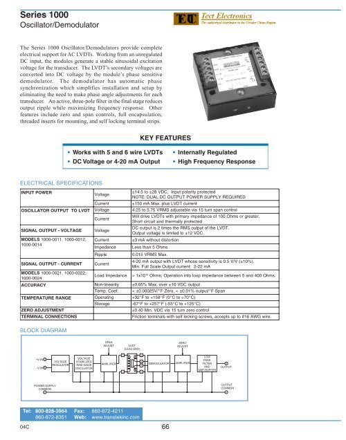
The <strong>Series</strong> <strong>1000</strong> <strong>Oscillator</strong>/<strong>Demodulator</strong>s provide complete<br />
electrical support for AC LVDTs. Working from an unregulated<br />
DC input, the modules generate a stable sinusoidal excitation<br />
voltage for the transducer. The LVDT’s secondary voltages are<br />
converted into DC voltage by the module’s phase sensitive<br />
demodulator. The demodulator has automatic phase<br />
synchronization which simplifies installation and setup by<br />
eliminating the need to make phase angle adjustments for each<br />
transducer. An active, three-pole filter in the final stage reduces<br />
output ripple while maximizing frequency response. Other<br />
features include zero and span controls, full encapsulation,<br />
threaded inserts for mounting, and self locking terminal strips.<br />
KEY FEATURES<br />
• Works with 5 and 6 wire LVDTs<br />
• DC Voltage or 4-20 mA Output<br />
• Internally Regulated<br />
• High Frequency Response<br />
ELECTRICAL SPECIFICATIONS<br />
INPUT POWER<br />
OSCILLATOR OUTPUT<br />
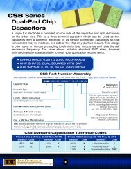
BLOCK DIAGRAM<br />
TO LVDT<br />
SIGNAL OUTPUT - VOLTAGE<br />
M ODELS <strong>1000</strong>-0011, <strong>1000</strong>-0012,<br />
<strong>1000</strong>-0014<br />
SIGNAL OUTPUT - CURRENT<br />
M ODELS <strong>1000</strong>-0021, <strong>1000</strong>-0022,<br />
<strong>1000</strong>-0024<br />
ACCURACY<br />
TEMPERATURE RANGE<br />
ZERO ADJUSTMENT<br />
Voltage<br />
Current<br />
Voltage<br />
Current<br />
Voltage<br />
Current<br />
Impedance<br />
±14.5 to ±28 VDC, Input polarity protected<br />
NOTE: DUAL DC OUTPUT POWER SUPPLY REQUIRED<br />
±150 mA Max. plus LVDT current<br />
4.25 to 5.75 VRMS adjustable via 15 turn span control<br />
Will drive LVDTs with primary impedance<br />
Short circuit and thermally protected<br />
DC output is 2 times the RMS output of<br />
Output voltage is limited to ±12 VDC.<br />
±3 mA without distortion<br />
Less than 5 Ohms<br />
R ipple<br />
0.015 VRMS Max.<br />
Current<br />
Load<br />
Impedance 1x10<br />
Non-linearity<br />
4-20 mA output with LVDT whose sensitivity<br />
Min. Full Scale Output current: 2-22 mA<br />
of 100 Ohms or greater.<br />
the LVDT.<br />
is 0.5 V/V (±10%).<br />
0<br />
> 1 Ohms; Operation into loop impedance between 5 and 400 Ohms .<br />
±0.05% Max. over ±10 VDC output<br />
T emp. Coef. < ±0.00025V/<br />
° F Zero, < ±0.01% output/<br />
° F Span<br />
Operating<br />
+ 32° F to +158° F ( 0° C to +70° C)<br />
Storage<br />
- 67° F to +257° F (-55° C to +125° C)<br />
±0.40 Min. VDC via 15 turn zero control<br />
T ERMINAL CONNECTIONS<br />
Friction terminals with self locking screws, accepts up to #16 AWG wire.<br />
Tel: 800-828-3964 Fax: 860-872-4211<br />
860-872-8351 Web: www.transtekinc.com<br />
04C<br />
66
SERIES <strong>1000</strong><br />
<strong>Oscillator</strong>/<br />
<strong>Demodulator</strong><br />
INTERCONNECTION DIAGRAM<br />
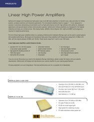
DIMENSIONAL DIAGRAM<br />
NOTE:<br />
1. 4 wire LVDT connection requires access to the center connection of both<br />
secondaries. One wire from each of the secondaries and the primary will<br />
be tied together and attached to COMMON. The remaining three leads<br />
will be connected as shown in the connection diagram.<br />
VOLTAGE AND 4-20 MA OUTPUT VERSIONS<br />
The equivalent models for voltage and 4-20 mA output are shown<br />
in the table below, along with frequency, phase angle and<br />
frequency response for each. All of these modules are physically<br />
identical and require the same dual bipolar voltage supply. The<br />
output pins 5 and 1 are used for the current output.<br />
VDC<br />
MODEL<br />
4-20 mA<br />
MODEL<br />
FREQUENCY<br />
KHz ±10%<br />
LVDT<br />
PHASE<br />
ANGLE<br />
Note: Current Loop impedance must be between 5 and 400<br />
Ohms for linear operation.<br />
FREQUENCY<br />
RESPONSE,<br />
Hz<br />
<strong>1000</strong>-0011<br />
<strong>1000</strong>-0021<br />
3 ALL<br />
> 500<br />
<strong>1000</strong>-0012<br />
<strong>1000</strong>-0022<br />
7 > 10 Degrees<br />
> <strong>1000</strong><br />
<strong>1000</strong>-0014<br />
<strong>1000</strong>-0024<br />
7 < 10 Degrees<br />
> <strong>1000</strong><br />
SALES OPTIONS<br />
Option # Description<br />
X0003: Provide special zero offset and/or sensitivity<br />
X0005: Provide special cutoff frequency<br />
67<br />
04C