Product Catalogue - GateWay Valve & Fitting Ltd. GateWay Valve ...
Product Catalogue - GateWay Valve & Fitting Ltd. GateWay Valve ...
Product Catalogue - GateWay Valve & Fitting Ltd. GateWay Valve ...

Create successful ePaper yourself
Turn your PDF publications into a flip-book with our unique Google optimized e-Paper software.
MODEL<br />
• Accurate Pressure Control<br />
• Optional Check Feature<br />
• Fast Opening to Maintain Line Pressure<br />
• Slow Closing to Prevents Surges<br />
• Completely Automatic Operation<br />
50-01<br />
(Full Internal Port)<br />
650-01<br />
(Reduced Internal Port)<br />
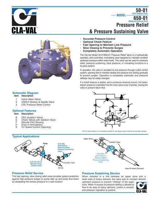
Pressure Relief<br />
& Pressure Sustaining <strong>Valve</strong><br />
The Cla-Val Model 50-01/650-01 Pressure Relief <strong>Valve</strong> is a hydraulically<br />
operated, pilot-controlled, modulating valve designed to maintain constant<br />
upstream pressure within close limits. This valve can be used for pressure<br />
relief, pressure sustaining, back pressure, or unloading functions in a<br />
by-pass system.<br />
In operation, the valve is actuated by line pressure through a pilot control<br />
system, opening fast to maintain steady line pressure but closing gradually<br />
to prevent surges. Operation is completely automatic and pressure<br />
settings may be easily changed.<br />
If a check feature is added, and a pressure reversal occurs, the downstream<br />
pressure is admitted into the main valve cover chamber, closing the<br />
valve to prevent return flow.<br />
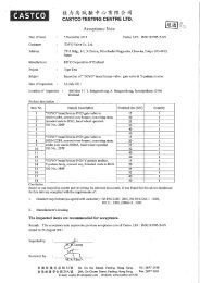
Schematic Diagram<br />
Item Description<br />
1 Hytrol (Main <strong>Valve</strong>)<br />
2 X42N-2 Strainer & Needle <strong>Valve</strong><br />
3 CRL Pressure Relief Control<br />
Optional Features<br />
Item Description<br />
B CK2 (Isolation <strong>Valve</strong>)<br />
D Check <strong>Valve</strong>s with Isolation <strong>Valve</strong><br />
F Remote Pilot Sensing<br />
H Drain to Atmosphere<br />
S CV Speed Control (Opening)<br />
F<br />
B1<br />
D1<br />
2<br />
INLET<br />
B1<br />
1<br />
S<br />
D2<br />
D3<br />
3<br />
OUTLET<br />
B2<br />
DRAIN TO<br />
ATMOSPHERE<br />
The "D check feature on a vertically installed 6" and larger valves must be horizontally oriented.<br />
H<br />
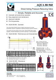
Typical Applications<br />
Upper Zone<br />
Supply<br />
CLA-VAL 60-73<br />
Booster Pump<br />
Control <strong>Valve</strong><br />
Pump<br />
CLA-VAL<br />
50-01/650-01<br />
Pressure Relief<br />
Pressure Sustaining<br />
<strong>Valve</strong><br />
Service<br />
Isolation <strong>Valve</strong><br />
CLA-VAL<br />
50-01/650-01<br />
Pressure Relief<br />
Pressure Sustaining<br />
<strong>Valve</strong><br />
Isolation <strong>Valve</strong><br />
Area Of Heavy Demand<br />
Pressure Relief Service<br />
This fast opening, slow closing relief valve provides system protection<br />
against high pressure surges on pump start up and pump shut down<br />
by dissipating the excess pressure to a safe location.<br />
Pressure Sustaining Service<br />
When installed in a line between an upper zone and a<br />
lower area of heavy demand, the valve acts to maintain desired<br />
upstream pressure to prevent "robbing" of the upper<br />
zone. Water in excess of pressure setting is allowed to<br />
flow to an area of heavy demand, control is smooth,<br />
and pressure regulation is positive.
Model 50-01 (Uses Basic <strong>Valve</strong> Model 100-01)<br />
Pressure Ratings (Recommended Maximum Pressure - psi)<br />
<strong>Valve</strong> Body & Cover<br />
Grade<br />
Material<br />
ANSI<br />
Standards*<br />
Pressure Class<br />
Flanged<br />
150 lb. 300 lb.<br />
End**<br />
Threaded<br />
Details<br />
ASTM A536 Ductile Iron B16.42 250 400 400<br />
ASTM A216-WCB Cast Steel B16.5 285 400 400<br />
ASTM B62 Bronze B16.24 225 400 400<br />
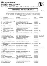
Dimensions<br />
(In inches)<br />
100-01 (Globe)<br />
B<br />
Note:<br />
* ANSI standards are for flange dimensions only.<br />
Flanged valves are available faced but not drilled.<br />
** End Details machined to ANSI B2.1 specifications.<br />
Materials<br />
Component<br />
Standard Material Combinations<br />
Body & Cover Ductile Iron Cast Steel Bronze<br />
Available Sizes 1 1 ⁄4" - 36" 1 1 ⁄4" - 16" 1 1 ⁄4" - 16"<br />
Disc Retainer &<br />
Diaphragm Washer<br />
Cast Iron Cast Steel Bronze<br />
Trim: Disc Guide,<br />
Bronze is Standard<br />
Seat & Cover Bearing Stainless Steel is Optional<br />
Disc<br />
Buna-N ® Rubber<br />
Diaphragm<br />
Nylon Reinforced Buna-N ® Rubber<br />
Stem, Nut & Spring<br />
Stainless Steel<br />
For material options not listed, consult factory.<br />
Cla-Val manufactures valves in more than 50 different alloys.<br />
100-01 (Angle)<br />
Model 50-01 Dimensions (In Inches)<br />
<strong>Valve</strong> Size (Inches) 1 1 ⁄4-1 1 ⁄2 2 2 1 ⁄2 3 4 6 8 10 12 14 16 24 36<br />
A Threaded 7.25 9.38 11.00 12.50 — — — — — — — — —<br />
AA 150 ANSI 8.50* 9.38 11.00 12.00 15.00 20.00 25.38 29.75 34.00 39.00 41.38 61.50 76.00<br />
AAA 300 ANSI 9.00* 10.00 11.62 13.25 15.62 21.00 26.38 31.12 35.50 40.50 43.50 63.24 78.00<br />
B Dia. 5.62 6.62 8.00 9.12 11.50 15.75 20.00 23.62 28.00 32.75 35.50 53.16 66.00<br />
C Max. 5.50 6.50 7.56 8.19 10.62 13.38 16.00 17.12 20.88 24.19 25.00 43.93 61.50<br />
D Threaded 3.25 4.75 5.50 6.25 — — — — — — — — —<br />
DD 150 ANSI 4.00* 4.75 5.50 6.00 7.50 10.00 12.75 14.88 17.00 19.50 20.81 — —<br />
DDD 300 ANSI 4.25* 5.00 5.88 6.38 7.88 10.50 13.25 15.56 17.75 20.25 21.62 — —<br />
E 1.12 1.50 1.69 2.56 3.19 4.31 5.31 9.25 10.75 12.62 15.50 17.75 24.56<br />
F 150 ANSI 2.50 3.00 3.50 3.75 4.50 5.50 6.75 8.00 9.50 10.50 11.75 19.25 28.00<br />
FF 300 ANSI 3.06 3.25 3.75 4.13 5.00 6.25 7.50 8.75 10.25 11.50 12.75 — —<br />
G Threaded 1.88 3.25 4.00 4.50 — — — — — — — — —<br />
GG 150 ANSI 4.00* 3.25 4.00 4.00 5.00 6.00 8.00 8.62 13.75 14.88 15.69 — —<br />
GGG 300 ANSI 4.25* 3.50 4.31 4.38 5.31 6.50 8.50 9.31 14.50 15.62 16.50 — —<br />
H NPT Body Tapping<br />
3<br />
⁄8<br />
3<br />
⁄8<br />
1<br />
⁄2<br />
1<br />
⁄2<br />
3<br />
⁄4<br />
3<br />
⁄4 1 1 1 1 1 1 2<br />
J NPT Cover Center Plug 1<br />
⁄4<br />
1<br />
⁄2<br />
1<br />
⁄2<br />
1<br />
⁄2<br />
3<br />
⁄4<br />
3<br />
⁄4 1 1 1 1 ⁄4 1 1 ⁄2 2 1 1 ⁄2 2<br />
K NPT Cover Tapping<br />
3<br />
⁄8<br />
3<br />
⁄8<br />
1<br />
⁄2<br />
1<br />
⁄2<br />
3<br />
⁄4<br />
3<br />
⁄4 1 1 1 1 1 1 2<br />
<strong>Valve</strong> Stem Internal<br />
Thread UNF<br />
10-32 10-32 10-32 1<br />
⁄4-28 1<br />
⁄4-28 3<br />
⁄8-24 3<br />
⁄8-24 3<br />
⁄8-24 3<br />
⁄8-24 3<br />
⁄8-24 1<br />
⁄2-20 3<br />
⁄4-16 3<br />
⁄4-16<br />
Stem Travel 0.4 0.6 0.7 0.8 1.1 1.7 2.3 2.8 3.4 4.0 4.5 6.75 10.12<br />
Approx. Ship Wt. Lbs. 15 35 50 70 140 285 500 780 1165 1600 2265 6200 11470<br />
X Pilot System 11.00 13.00 14.00 15.00 17.00 29.00 31.00 33.00 36.00 40.00 40.00 68.00 86.00<br />
Y Pilot System 9.00 9.00 10.00 11.00 12.00 20.00 22.00 24.00 26.00 29.00 30.00 39.00 45.00<br />
Z Pilot System 9.00 9.00 10.00 11.00 12.00 20.00 22.00 24.00 26.00 29.00 30.00 39.00 45.00<br />
*1 1 ⁄2 " Size Only
Model 650-01 (Uses Basic <strong>Valve</strong> Model 100-20)<br />
Dimensions<br />
(In inches)<br />
Pressure Ratings (Recommended Maximum Pressure - psi)<br />
<strong>Valve</strong> Body & Cover<br />
Grade<br />
Material<br />
ANSI<br />
Standards*<br />
Pressure Class<br />
Flanged<br />
150 lb. 300 lb.<br />
100-20 (Globe)<br />
ASTM A536 Ductile Iron B16.42 250 400<br />
ASTM A216-WCB Cast Steel B16.5 285 400<br />
ASTM B62 Bronze B16.24 225 400<br />
Note:<br />
*ANSI standards are for flange dimensions only.<br />
Flanged valves are available faced but not drilled.<br />
Materials<br />
Component<br />
Standard Material Combinations<br />
Body & Cover Ductile Iron Cast Steel Bronze<br />
Available Sizes 3" - 48" 3" - 16" 3" - 16"<br />
Disc Retainer &<br />
Diaphragm Washer<br />
Cast Iron Cast Steel Bronze<br />
Trim: Disc Guide,<br />
Bronze is Standard<br />
Seat & Cover Bearing Stainless Steel is Optional<br />
Disc<br />
Buna-N ® Rubber<br />
Diaphragm<br />
Nylon Reinforced Buna-N ® Rubber<br />
Stem, Nut & Spring<br />
Stainless Steel<br />
For material options not listed, consult factory.<br />
Cla-Val manufactures valves in more than 50 different alloys.<br />
100-20 (Angle)<br />
Model 650-01 Dimensions (In Inches)<br />
<strong>Valve</strong> Size (Inches) 3 4 6 8 10 12 14 16 18 20 24 30<br />
A 150 ANSI 10.25 13.88 17.75 21.38 26.00 30.00 34.25 35.00 42.12 48.00 48.00 63.25<br />
AA 300 ANSI 11.00 14.50 18.62 22.38 27.38 31.50 — 36.62 43.63 49.62 49.75 —<br />
B Dia. 6.62 9.12 11.50 15.75 20.00 23.62 28.00 28.00 35.44 35.44 35.44 53.19<br />
C Max. 7.00 8.62 11.62 15.00 17.88 21.00 20.88 25.75 25.00 31.00 31.00 43.94<br />
D 150 ANSI — 6.94 8.88 10.69 — — — — — — — —<br />
DD 300 ANSI — 7.25 9.38 11.19 — — — — — — — —<br />
E 150 ANSI — 5.50 6.75 7.25 — — — — — — — —<br />
EE 300 ANSI — 5.81 7.25 7.75 — — — — — — — —<br />
F 150 ANSI 3.75 4.50 5.50 6.75 8.00 9.50 11.00 11.75 15.88 14.56 17.00 19.88<br />
FF 300 ANSI 4.12 5.00 6.25 7.50 8.75 10.25 — 12.75 15.88 16.06 19.00 —<br />
H NPT Body Tapping<br />
3<br />
⁄8<br />
1<br />
⁄2<br />
3<br />
⁄4<br />
3<br />
⁄4 1 1 1 1 1 1 1 1<br />
J NPT Cover Center Plug<br />
1<br />
⁄2<br />
1<br />
⁄2<br />
3<br />
⁄4<br />
3<br />
⁄4 1 1 1 1 ⁄4 1 1 ⁄4 2 2 2 2<br />
K NPT Cover Tapping<br />
3<br />
⁄8<br />
1<br />
⁄2<br />
3<br />
⁄4<br />
3<br />
⁄4 1 1 1 1 1 1 1 1<br />
<strong>Valve</strong> Stem Internal<br />
Thread UNF<br />
10-32 1<br />
⁄4-28 1<br />
⁄4-28 3<br />
⁄8-24 3<br />
⁄8-24 3<br />
⁄8-24 3<br />
⁄8-24 3<br />
⁄8-24 1<br />
⁄2-20 1<br />
⁄2-20 1<br />
⁄2-20 3<br />
⁄4-16<br />
Stem Travel 0.6 0.8 1.1 1.7 2.3 2.8 3.4 3.4 3.4 4.5 4.5 6.5<br />
Approx. Ship Wt. Lbs. 45 85 195 330 625 900 1250 1380 1500 2551 2733 6500<br />
X Pilot System 13.00 15.00 27.00 30.00 33.00 36.00 36.00 41.00 40.00 46.00 55.00 68.00<br />
Y Pilot System 10.00 11.00 18.00 20.00 22.00 24.00 26.00 26.00 30.00 30.00 30.00 39.00<br />
Z Pilot System 10.00 11.00 18.00 20.00 22.00 24.00 26.00 26.00 30.00 30.00 30.00 39.00
These Symbols A and B Indicate Available Sizes<br />
<strong>Valve</strong> Selection<br />
Inches<br />
1 1 ⁄4 1 1 ⁄2 2 2 1 ⁄2 3 4 6 8 10 12 14 16 18 20 24 30 36<br />
mm<br />
32 40 50 65 80 100 150 200 250 300 350 400 450 500 600 750 900<br />
End Detail Threaded Threaded & Flanged Flanged<br />
Model<br />
50-01<br />
Basic <strong>Valve</strong><br />
100-01<br />
Suggested Flow<br />
(gpm)<br />
Suggested Flow<br />
(Liters/Sec)<br />
Globe A A A A A A A A A A A A A<br />
Angle B B B B B B B B B B B<br />
Max.<br />
Continuous 93 125 210 300 460 800 1800 3100 4900 7000 8400 11000 25000 50000<br />
Max. Surge<br />
120 280 470 670 1000 1800 4000 7000 11000 16000 19000 25000 56500 120000<br />
Max.<br />
Continuous 6 8 13 19 29 50 113 195 309 441 529 693 1575 3150<br />
Max. Surge<br />
13 18 30 42 63 113 252 441 693 1008 1197 1575 3560 7570<br />
Model<br />
650-01<br />
Basic <strong>Valve</strong><br />
100-20<br />
Suggested Flow<br />
(gpm)<br />
Suggested Flow<br />
(Liters/Sec)<br />
Globe A ** A A A A A A A A A A A<br />
Angle B B B<br />
Max.<br />
Continuous 260 580 1025 2300 4100 6400 9230 9230 16500 16500 16500 31300<br />
Max. Surge<br />
440 990 1760 3970 7050 11000 15900 15900 28200 28200 28200 56500<br />
Max.<br />
Continuous 16 37 65 145 258 403 581 581 1040 1040 1040 1972<br />
Max. Surge<br />
28 62 111 250 444 693 1002 1002 1777 1777 1777 3560<br />
650-01 is the reduced internal port size version of the 50-01.<br />
For 100-01 basic valves, suggested, flow calculations were based on flow through Schedule 40 Pipe. Maximum continuous flow is approx. 20 ft/sec (6.1 meters/sec) &<br />
maximum surge is approx. 45 ft/sec (13.7 meters/sec). For 100-20 basic valves, suggested, flow calculations were based on flow through the valve seat.<br />
Approx. 26 ft/sec (7.9 meters/sec) is used for continuous flow & 45 ft/sec (13.7 meters/sec) is used for surge flow. Maximum continuous flow through the valve seat for<br />
the 30" 100-20 is approx. 22 ft/sec (6.7 meters/sec).<br />
**Flanged End Detail Only<br />
Pilot System Specifications<br />
Adjustment Ranges<br />
0 to 75 psi Max.<br />
20 to 200 psi *<br />
100 to 300 psi<br />
*Supplied unless otherwise specified.<br />
Other ranges available, please consult factory.<br />
Temperature Range<br />
Water: to 180°F<br />
Materials<br />
Standard Pilot System Materials<br />
Pilot Control: Bronze ASTM B62<br />
Trim: Stainless Steel Type 303<br />
Rubber: Buna-N ® Synthetic Rubber<br />
Tubing & <strong>Fitting</strong>: Copper and Bronze<br />
Optional Pilot System Materials<br />
Pilot Systems are available with<br />
optional Aluminum, Stainless Steel or<br />
Monel materials at additional cost.<br />
When Ordering, Please Specify<br />
1. Catalog No. 50-01 or No. 650-01<br />
2. <strong>Valve</strong> Size<br />
3. Pattern - Globe or Angle<br />
4. Pressure Class<br />
5. Threaded or Flanged<br />
6. Trim Material<br />
7. Adjustment Range<br />
8. Desired Options<br />
9. When Vertically Installed<br />
E-50-01/650-01 (R-12/06)<br />
CLA-VAL<br />
PO Box 1325 Newport Beach CA 92659-0325<br />
Phone: 949-722-4800 Fax: 949-548-5441<br />
CLA-VAL CANADA<br />
4687 Christie Drive<br />
Beamsville, Ontario<br />
Canada LOR 1B4<br />
Phone: 905-563-4963<br />
Fax: 905-563-4040<br />
©COPYRIGHT CLA-VAL 2006 Printed in USA<br />
Specifications subject to change without notice.<br />
CLA-VAL EUROPE<br />
Chemin dés Mesanges 1<br />
CH-1032 Romanel/<br />
Lausanne, Switzerland<br />
Phone: 41-21-643-15-55<br />
Fax: 41-21-643-15-50<br />
www.cla-val.com<br />
Represented By: