
Create successful ePaper yourself
Turn your PDF publications into a flip-book with our unique Google optimized e-Paper software.
<strong>Screw</strong> <strong>Thread</strong> <strong>Design</strong><br />
<strong>Screw</strong> <strong>Thread</strong> Fundamentals<br />
A screw thread is defined as a ridge of uniform section in the form of a helix on either the external<br />
or internal surface of a cylinder. Internal threads refer to those on nuts and tapped holes, while<br />
external threads are those on bolts, studs, or screws.<br />
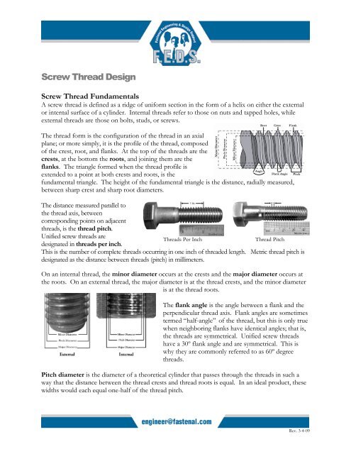
The thread form is the configuration of the thread in an axial<br />
plane; or more simply, it is the profile of the thread, composed<br />
of the crest, root, and flanks. At the top of the threads are the<br />
crests, at the bottom the roots, and joining them are the<br />
flanks. The triangle formed when the thread profile is<br />
extended to a point at both crests and roots, is the<br />
fundamental triangle. The height of the fundamental triangle is the distance, radially measured,<br />
between sharp crest and sharp root diameters.<br />
The distance measured parallel to<br />
the thread axis, between<br />
corresponding points on adjacent<br />
threads, is the thread pitch.<br />
Unified screw threads are<br />
designated in threads per inch.<br />
<strong>Thread</strong>s Per Inch<br />
<strong>Thread</strong> Pitch<br />
This is the number of complete threads occurring in one inch of threaded length. Metric thread pitch is<br />
designated as the distance between threads (pitch) in millimeters.<br />
On an internal thread, the minor diameter occurs at the crests and the major diameter occurs at<br />
the roots. On an external thread, the major diameter is at the thread crests, and the minor diameter<br />
is at the thread roots.<br />
The flank angle is the angle between a flank and the<br />
perpendicular thread axis. Flank angles are sometimes<br />
termed “half-angle” of the thread, but this is only true<br />
when neighboring flanks have identical angles; that is,<br />
the threads are symmetrical. Unified screw threads<br />
have a 30º flank angle and are symmetrical. This is<br />
why they are commonly referred to as 60º degree<br />
threads.<br />
Pitch diameter is the diameter of a theoretical cylinder that passes through the threads in such a<br />
way that the distance between the thread crests and thread roots is equal. In an ideal product, these<br />
widths would each equal one-half of the thread pitch.<br />
Rev. 3-4-09
An intentional clearance is created between mating threads when the nut and bolt are manufactured.<br />
This clearance is known as the allowance. Having an allowance ensures that when the threads are<br />
manufactured there will be a positive space between them. For fasteners, the allowance is generally<br />
applied to the external thread. Tolerances are specified amounts by which dimensions are<br />
permitted to vary for convenience of manufacturing. The tolerance is the difference between the<br />
maximum and minimum permitted limits.<br />
<strong>Thread</strong> Fit<br />
<strong>Thread</strong> fit is a combination of allowances and tolerances and a measure of tightness or looseness<br />
between them. A clearance fit is one that provides a free running assembly and an interference fit<br />
is one that has a positive interference thus requiring tools for the initial run-down of the nut.<br />
For Unified inch screw threads there are six standard classes of fit: 1B, 2B, and 3B for internal<br />
threads; and 1A, 2A, and 3A for external threads. All are considered clearance fits. That is, they<br />
assemble without interference. The higher the class number, the tighter the fit. The ‘A’ designates<br />
an external thread, and ‘B’ designates an internal thread.<br />
• Classes 1A and 1B are considered an extremely loose tolerance thread fit. This class is<br />
suited for quick and easy assembly and disassembly. Outside of low-carbon threaded rod or<br />
machine screws, this thread fit is rarely specified.<br />
• Classes 2A and 2B offer optimum thread fit that balances fastener performance,<br />
manufacturing, economy, and convenience. Nearly 90% of all commercial and industrial<br />
fasteners use this class of thread fit.<br />
• Classes 3A and 3B are suited for close tolerance fasteners. These fasteners are intended for<br />
service where safety is a critical design consideration. This class of fit has restrictive<br />
tolerances and no allowance. Socket products generally have a 3A thread fit.<br />
The following illustration demonstrates the<br />
pitch diameter allowances on a ¾-10 bolt and<br />
nut.<br />
The axial distance through which the fully<br />
formed threads of both the nut and bolt are in<br />
contact is called the length of thread<br />
engagement. The depth of thread<br />
engagement is the distance the threads overlap<br />
in a radial direction. The length of thread<br />
engagement is one of the key strength aspects<br />
and one of the few which the designer may be<br />
able to control.<br />
Rev. 3-4-09
Per the acceptance requirements of ASME B1.3, System 21, the allowance<br />
specified for the Class 2A external threads is used to accommodate the<br />
plating thickness. The plain finished parts (or plated parts prior to plating)<br />
would be tested for adherence to these tolerances with a 2A Go/No-Go<br />
thread gauge. The 2A Go gauge would ensure the pitch diameter falls<br />
below the maximum requirement; the No-Go gauge would verify that the<br />
pitch diameter is above the minimum requirement. A standard electro-zinc<br />
plated 2A part would be gauged with the Class 3A Go (due to the plating<br />
metal thickness) and 2A No-Go gauge after plating.<br />
Go and No-Go Gauges are<br />
threaded rings that are tapped<br />
in such a way that they ensure<br />
proper tolerancing of parts.<br />
Similar devices are available<br />
for internally threaded<br />
fasteners.<br />
<strong>Thread</strong> damages such as dents, scrapes,<br />
nicks, or gouges and plating build-up are<br />
not cause for rejections unless they<br />
impair function and usability. <strong>Thread</strong>s<br />
that do not freely accept the appropriate<br />
Go ring gauge shall be inspected by<br />
allowing the screwing of the gauge with<br />
maximum allowable torque value of:<br />
Torque = 145 x d 3 (for inch series), where Torque is in-lbs. and d is<br />
diameter in inches- IFI 166<br />
Minor thread nicking on external<br />
threads may still be found<br />
acceptable.<br />
Torque = 0.001 x d 3 (for metric series), where Torque is Nm and d is diameter in mm- IFI 566<br />
<strong>Thread</strong> Series<br />
There are three standard thread series in the Unified screw thread system that are highly important<br />
for fasteners: UNC (coarse), UNF (fine), and 8-UN (8 thread). A chart listing the standards sizes<br />
and thread pitches with their respective thread stress areas is listed in the <strong>Fastenal</strong> Technical<br />
Reference Guide, along with a special series designated UNS.<br />
Below are some of the aspects of fine and coarse threads.<br />
Rev. 3-4-09
Fine <strong>Thread</strong><br />
• Since they have larger stress<br />
areas the bolts are stronger<br />
in tension<br />
• Their larger minor<br />
diameters develop higher<br />
torsional and transverse<br />
shear strengths<br />
• They can tap better in thinwalled<br />
members<br />
• With their smaller helix<br />
angle, they permit closer<br />
adjustment accuracy<br />
Coarse <strong>Thread</strong><br />
• Stripping strengths are greater<br />
for the same length of<br />
engagement<br />
• Improved fatigue resistance<br />
• Less likely to cross thread<br />
• Quicker assembly and<br />
disassembly<br />
• Tap better in brittle materials<br />
• Larger thread allowances<br />
allow for thicker platings and<br />
coatings<br />
Numerous arguments have been made for using either fine or coarse threads; however, with the<br />
increase in automated assembly processes, bias towards the coarse thread series has developed.<br />
UNR <strong>Thread</strong>s<br />
The UNR thread is a modified version of a standard UN thread. The single difference is a<br />
mandatory root radius with limits of 0.108 to 0.144 times the thread pitch. When first introduced<br />
decades ago, it was necessary to specify UNR (rounded root) threads. Today, all fasteners that are<br />
roll threaded should have a UNR thread because thread rolling dies with rounded crests are now the<br />
standard method for manufacturing most threads.<br />
UNJ <strong>Thread</strong>s<br />
UNJ thread is a thread form having root radius limits of 0.150 to 0.180 times the thread pitch.<br />
With these enlarged radii, minor diameters of external thread increase and intrude beyond the basic<br />
profile of the UN and UNR thread forms. Consequently, to offset the possibility of interference<br />
between mating threads, the minor diameters of the UNJ internal threads had to be increased.<br />
3A/3B thread tolerances are the standard for UNJ threads. UNJ threads are now the standard for<br />
aerospace fasteners and have some usage in highly specialized industrial applications.<br />
UNJ bolts are like UNR, but the curve of the thread root is gentler which requires that it be<br />
shallower. In fact, the thread root is so shallow that the bolt thread cannot mate with a UN nut, so<br />
there is a UNJ nut specification as well.<br />
<strong>Thread</strong> Production<br />
<strong>Thread</strong>s can be produced by either cutting or rolling operations. The shank of a blank designed for<br />
cut threading will be full-size from the fillet under the head to the end of the bolt. Producing cut<br />
Rev. 3-4-09
threads involves removing the material from a bolt blank with a cutting die or lathe in order to<br />
produce the thread. This interrupts the grain flow of the material.<br />
Rolled threads are formed by rolling the reduced diameter (approximately equal to the pitch<br />
diameter) portion of the shank between two reciprocating serrated dies. The dies apply pressure,<br />
compressing the minor diameter (thread roots) and forcing that material up to form the major<br />
diameter (thread crests). Imagine squeezing a balloon with your hand; you compress with your<br />
fingers to form the valley, while allowing part of the balloon to expand between your fingers. This is<br />
the concept behind roll threading. Rolled threads have several advantages: more accurate and<br />
uniform thread dimension, smoother thread surface, and generally greater thread strength<br />
(particularly fatigue and shear strength).<br />
<strong>Thread</strong> cutting requires the least amount of tooling costs. It is generally only used for large diameter<br />
or non-standard externally threaded fasteners. <strong>Thread</strong> cutting is still the most commonly used<br />
method for internal threads.<br />
<strong>Thread</strong> Strength<br />
Two fundamentals must be considered when designing a threaded connection.<br />
1. Ensure that the threaded fasteners were manufactured to a current ASTM, ANSI, DIN, ISO or<br />
other recognized standard.<br />
2. Ensure that the design promotes bolts to break in tension prior to the female and/or male<br />
threads stripping. A broken bolt is an obvious failure. However, when the threads strip prior to<br />
the bolt breaking, the failure may go unnoticed until after the fastener is put in service.<br />
Rev. 3-4-09
The strength of bolts loaded in tension can be<br />
easily determined by the ultimate tensile<br />
strength. To determine the amount of force<br />
required to break a bolt, multiply its ultimate<br />
tensile strength by its tensile stress area, As<br />
Internal <strong>Thread</strong> Strength Formula<br />
F = Su * Ats<br />
Su = shear strength of the nut or tapped material<br />
Ats = cross-sectional area through which the shear occurs<br />
Determining the strength of the threads is more complicated. Since the male threads pull past the<br />
female threads, or vice-versa, the threads fail in shear and not in tension. Therefore, the stripping<br />
strength of an assembly depends on the shear strength of the nut and bolt materials.<br />
Formula for Ats (when shear occurs at the roots of the thread)<br />
Ats = ϖ n Le Dsmin[1/(2n) + 0.57735 (Dsmin – Enmax)]<br />
Dsmin = min major dia.<br />
of external threads<br />
Enmax = max pitch<br />
dia. of internal threads<br />
n = thread per<br />
inch<br />
Le = length of thread<br />
engagement<br />
To determine the force required to strip the threads, multiply the shear strength by the cross<br />
sectional area being sheared. The difficulty lies in determining the<br />
cross sectional area in which the shear will occur. Here are three<br />
possible scenarios for this type of failure.<br />
1. The nut material is stronger than the bolt material. In this<br />
example, the nut threads will shear out the bolt threads. The<br />
failure will occur at the root of the bolt threads.<br />
2. The bolt material is stronger than the nut material. In this<br />
scenario, the bolt threads will shear out the nut threads. The<br />
failure will occur at the root of the nut threads.<br />
3. The nut and bolt are the same strength. In this scenario, both<br />
threads will strip simultaneously. This failure will occur at the<br />
pitch line.<br />
The tensile strength of most fasteners is usually specified, whereas<br />
shear strength is not. In order to avoid shearing the threads, ensure<br />
Taking proper precautions during<br />
the design phase is vital to<br />
avoiding thread failure. Once the<br />
first engaged thread begins to<br />
shear, the threads behind it will<br />
also shear in rapid succession.<br />
that the length of engagement between the internal and external thread is long enough to provide<br />
adequate cross-sectional thread area.<br />
Failure scenarios #1 and #3 can typically be avoided by ensuring proper thread engagement. With<br />
proper engagement, those scenarios would result in a tensile failure of the bolt rather than thread<br />
stripping.<br />
Rev. 3-4-09
Generally the hardness and the actual material strength of a nut<br />
is less than the bolt. For example, if you look at the hardness of<br />
an SAE J995 Grade 8 nut (HRC 24-32 up to 5/8-in diameter), it<br />
is likely to be less than the SAE J429 Grade 8 bolt (HRC 33-39).<br />
This is designed to yield the nut threads to ensure the load is not<br />
carried solely by the first thread. As the thread yields, the load is<br />
further distributed to the next five threads. Even with the load<br />
distribution, the first engaged thread still takes the majority of<br />
the load. In a typical 7/8-9 Grade 8 nut, the first engaged<br />
thread carries 34% of the load. Using internally threaded materials with higher strengths and<br />
hardness can often result in fatigue and/or loosening.<br />
The strength capacities of standard nuts are listed as the nut’s proof stress. This should not be<br />
confused with the proof strength of the bolts. Proof stress is the ultimate load the nut can support<br />
without thread failure. For design purposes, the most important aspect of choosing the appropriate<br />
nut is to select a nut with a proof stress equal to or greater than the ultimate tensile strength of the<br />
bolt.<br />
Caution: It appears that one could theoretically increase the thread strength by increasing the length<br />
of engagement. However, as illustrated in the Load Distribution chart above, the first thread will be<br />
taking the majority of the applied load. For carbon steel fasteners (including tapped holes) the<br />
length of engagement would be limited to approximately one nominal diameter (approximately 1-<br />
1/2 times the diameter for aluminum). After that, there is no appreciable increase in strength. Once<br />
the applied load has exceeded the first thread’s capacity, it will fail and subsequently cause the<br />
remaining threads to fail in succession.<br />
Returning to the discussion of fundamentals in thread connection design, the nut or tapped hole<br />
should support more load than the bolt. Thus, the design criteria for threaded connections also<br />
leads to nut selection criteria which help the designer ensure functionality in the joint. The<br />
following are the basic rules:<br />
1. Ensure that the nut adheres to a specification which is<br />
compatible with the specification of the bolt (ASTM<br />
A193 and ASTM A194, SAE J429 and SAE J995, etc.)<br />
Ensure that the selected nut has a proof stress greater than<br />
or equal to the tensile strength of the bolt.<br />
If the nut proof stress does not exceed the<br />
proof strength of the bolt, stripping failure<br />
is very likely.<br />
Rev. 3-4-09