PA28RT POH - Seattle Flight Instruction
PA28RT POH - Seattle Flight Instruction
PA28RT POH - Seattle Flight Instruction

Create successful ePaper yourself
Turn your PDF publications into a flip-book with our unique Google optimized e-Paper software.
ARROW IV<br />
PiLOT'S<br />
OPERATING<br />
HANDBOOK<br />
Q€-VWN . AND<br />
5.Vo. 2$C -4!3/i80Sb<br />
FAA APPROVED<br />
AIRPLANE FLIGHT MANUAL<br />
AIRPLANE<br />
SERIAL NO<br />
PA-20RT-201<br />
REPORT: VB-930 FAA APPROVED BY:<br />
.ATE OF APPROVAL:<br />
NOVEMBER 30,1978<br />
WARD WANS<br />
D.O.A. NO. SO-1<br />
PlPER AIRCRAFT CORPORATlON<br />
VER0 BEACH, FLORIDA<br />
FAA APPROVED IN NORMAL CATEGORY BASED ON CAR 3. THlS HANOBOOK<br />
INCLUDESTHE MATERIAL REQUIRED TO BE FURNISHED TO THE PILOT BY CÄR 3AND<br />
CONSTITUTES THE APPROVED AIRPLANE FUGHT MANUAL AND MUS1 BE CARRIED<br />
IN THE AIRPLANE AT A U TiMES.
WARNING<br />
T BE EXERCISED TO LIMIT THE USE 0<br />
APPLICABLE AIRCRAFT. THIS HANS,<br />
DE¿ PA-28RT-201, ARROW IV<br />
I ' .
.PILOT'S OPER TING HANDBOOK LOG OF REVISIONS<br />
Current Revisions to the PA-28RT-201 Arrow IV Pilot's Operating Handbook,<br />
REPQRT: VB-930 issued November 30, 1978.<br />
Revision<br />
Number and<br />
. Code<br />
Re v i s e d<br />
Pages<br />
Description of Revision<br />
I<br />
P<br />
i<br />
{<br />
!I<br />
$<br />
FAA Approval $ .I<br />
Signature and<br />
Date<br />
' <<br />
_c<br />
Rev. 1<br />
761 690<br />
(PR7902 16)<br />
3-1 1<br />
3-15<br />
3-16<br />
4-14<br />
6-2<br />
6-17,<br />
6-20,<br />
6-23<br />
6-33<br />
7-17<br />
9-i<br />
9-9<br />
through<br />
9-12<br />
9-13<br />
through<br />
9-18<br />
9-19<br />
through<br />
9-28<br />
Revised first para<br />
Revised fmt & third para.<br />
Correct report number.<br />
Revised second para.<br />
Revised first & second para.<br />
Revised page headings.<br />
Revised Autopilots info.<br />
Revised note to waming &<br />
changed anti-collision to<br />
strobe.<br />
Revised Table of Contents.<br />
Added AutoFlite I1 Autopilot<br />
Insti. Supplement.<br />
Added AutoControl IIIB<br />
Autopilot Instl. Supplement.<br />
Added AltiMatic IIIC Autopilot<br />
Instl. Supplement.<br />
W d L<br />
Ward Evans<br />
Feb. 16, 1979<br />
Rev. 2<br />
761 690<br />
(PR7904 13)<br />
6-42<br />
6-43<br />
7-29,<br />
7-30<br />
7-3 1<br />
Revised item 349; added item<br />
350; relocated item 351 to pg,<br />
6-43.<br />
Added item 351 from pg.<br />
6-42.<br />
Revised para. 7.39.<br />
Added pg.<br />
Ward Evans<br />
April 13, 1979<br />
REPORT: VB-930
PILOT'S OPERATING HANDBOOK LOG OF REVISIONS (cont)<br />
Revision<br />
Number and<br />
Code<br />
Rev. 3<br />
761 690<br />
(PR800729)<br />
Revised<br />
Pages<br />
...<br />
111<br />
1-3<br />
2-3<br />
2-4<br />
3-15<br />
4-i<br />
4-9<br />
4-18<br />
4-19<br />
4-20<br />
4-26<br />
5-5<br />
5-6<br />
5-7<br />
5-9<br />
5-19<br />
5-24<br />
5-24a<br />
5-24b<br />
5-25<br />
5-26<br />
5-26a<br />
5-26b<br />
5-27<br />
Description of Revision<br />
Revised ser. no. applicability.<br />
Revised item 1.3 (c).<br />
Revised item 2.7 (c) and (e).<br />
Revised item 2.9 (c).<br />
Revised para. numbers, rpm<br />
and KIAS.<br />
Revised Table of Contents.<br />
Revised para. 4.5.<br />
Relocated para. 4.21 from<br />
page 4-19; added para. 4.23<br />
info. from pg. 4-20.<br />
Relocated info. to pg. 4-18;<br />
added para. 4.23 from pg. 4-20<br />
Relocated para. 4.23 to pg.<br />
4-19; added note to para. 4.25.<br />
Revised warning.<br />
Revised para. 5.5. (c) (3)*(4).<br />
(5).<br />
Revised para. 5.5 (d) (I), (2),<br />
(3); revised power Setting in<br />
5.5 (e); revised 5.5 (e) (2).<br />
Revised para. 5.5 (e) (5).<br />
(0 (I)* (g) (1).<br />
Revised Table of Contents.<br />
Revised fig. 5-17.<br />
ReIocated fig. 5-23 to pg.<br />
5-24a.<br />
Added pg.; reiocated fig.<br />
5-23 from pg. 5-24.<br />
Added pg.; added fig. 5-24.<br />
Revised fig. 5-25.<br />
Revised fig. 5-27.<br />
Added pg.; added fig. 5-28.<br />
Added pg.<br />
Revised fig. 5-29<br />
:AA Approval<br />
Signaturc and<br />
Date<br />
i<br />
...<br />
! \.<br />
!<br />
I.<br />
I<br />
I<br />
i,<br />
i<br />
REPORT VB-930<br />
M
PILOT’S OPERATING I-IANDÜoOK LOG OF’ RE’VISIONS (contj<br />
~~<br />
Revision<br />
Nuriibcr anc Rcviscd<br />
Code Pages<br />
5-28<br />
5-29<br />
(PR800299: 6-i<br />
(cont) 6- 1<br />
6-3<br />
6-4<br />
6-5<br />
6-14<br />
6-15<br />
6-16<br />
6-18<br />
6-30<br />
6-3 I<br />
6-32<br />
6-34<br />
6-34a<br />
6-34b<br />
6-35<br />
6-36<br />
7-3<br />
8-i<br />
,<br />
>d’<br />
Description of Revision<br />
~ ~ ~~<br />
Revised fig. 5-3 I .<br />
I
~ 7-10<br />
Revision<br />
Nurnbcr anc<br />
Code<br />
Reviscd<br />
Pagcs<br />
Dcscription of Rcvision<br />
FAA Approviil<br />
Signaturc ancl<br />
Datc<br />
I<br />
Rev. 4<br />
761 690<br />
(PR870131)<br />
Rcv. 5<br />
761 690<br />
(PR960906)<br />
vi-b<br />
2-9<br />
3-2.<br />
3-3,<br />
3-6<br />
3 9,<br />
3-10<br />
3-1 I.<br />
3-12<br />
3-15<br />
3-16<br />
4-9<br />
4-18<br />
4-19<br />
4-20<br />
4-25.<br />
4-26<br />
7-4<br />
7-6<br />
7-7<br />
7-8<br />
7-9<br />
7-1 1<br />
vi-b<br />
3-6,<br />
3- 15,<br />
8-1,<br />
8-2,<br />
8-3,<br />
8-11.<br />
'9- 13,<br />
Reviscd para. 2.25.<br />
Reviscd para. 3.3.<br />
Revised para. 3.9.<br />
Revised para. 3.13.<br />
Reviscd Para. 3.27.<br />
Relocated info. to pagc 3- 16.<br />
Revised para. 3.27.<br />
Relocated info from page 3-15.<br />
Reviscd para. 4.5.<br />
Revised para. 4.2 1.<br />
Relocaled info. to pagc 4- 19.<br />
Revised Para. 4-2 1.<br />
Relocated info from pagc 4- 18.<br />
Revised Para. 4.25.<br />
Revised Para. 4.39.<br />
Revised fig. 7- 1.<br />
Revised para. 7.1 I; rcvised<br />
fig. 7-3. Relocatcd info.<br />
from page 7-7.<br />
Reviscd para. 7.1 1.<br />
Relocated info. to pagc 7-6.<br />
Revised para. 7.1 1<br />
Revised fig. 7-5.<br />
Revised fig. 7-7.<br />
Revised fig. 7-9.<br />
Addcd Rev. 5 to L of R pg. -<br />
Reviscd para. 3.3.<br />
Revised para. 3.27.<br />
Revised para. 8.1.<br />
Revised Para. 8.3.<br />
Revised para. 8.3<br />
Reviscd Para. 8.19<br />
Removed Sec. 3(a)(2)<br />
+<br />
D.H. Trom Icr<br />
3khZ-<br />
Date<br />
Sept. 06. 1c 3 ,. ,<br />
-<br />
Dalc<br />
J<br />
j<br />
1'
TABLE OF CONTENTS<br />
SECTION 1<br />
SECTION 2<br />
.. 9ECTION 3<br />
SECTION 4<br />
SECTION 5<br />
SECTION 6<br />
SECTION 7<br />
SECTION 8<br />
SECTION 9<br />
SECTION 10<br />
GENERAL<br />
LI M ITATIO NS<br />
EMERGENCY PROCEDURES<br />
NORMAL PROCEDURES<br />
PERFORMANCE<br />
WEIGHT AND BALANCE<br />
DESCRIPTION AND OPERATION OF<br />
THE AIRPLANE AND ITS SYSTEMS<br />
AIRPLANE HANDLING, SERVlClNG<br />
AND MAINTENANCE<br />
SUPPLEMENTS<br />
SAFETY TlPS<br />
REPORT: VB-930<br />
..-.
-<br />
I ,
TABLE OF CONTENTS<br />
SECTION 1<br />
GENERAL<br />
& \<br />
0 '\<br />
Paragraph<br />
No.<br />
1.1<br />
1.3<br />
1.5<br />
1.7<br />
1.9<br />
1.11<br />
-- 1.13<br />
.<br />
1.15<br />
1.17<br />
1.19<br />
1.21<br />
Introduction .. .. . Engines .. Propellers . .. Fuel .........................,...... ............ Oil .................................. ........... Maximum Weights ....... Standard Airplane Weights Baggage Space .. Specific Loadings .................. ... Symbols, Abbreviations and Terminology .. . Conversion Factors ........................ ....,....<br />
Page<br />
No.<br />
1-1<br />
1-3<br />
1-3<br />
1-4<br />
1-4<br />
1-5<br />
1-5<br />
1-5<br />
1-5<br />
1-6<br />
1-12<br />
REPORT: VB-930<br />
..<br />
1<br />
(I<br />
!
!.<br />
j:
I ,<br />
PIPER AIRCRAFT CORPORATION SECTION 1!<br />
PA-28RT-201, ARRO W IV<br />
GENERAL<br />
SECTION I<br />
GENERAL<br />
, 1.1 INTRODUCTION<br />
\i<br />
This Pilot’s Operating Handbook is designed for maximum utilization<br />
as an Operating guide for the pilot. It includes the material requircd to be<br />
fumished to the pilot by CAR 3 and FAR Part 21 Subpart J. It also contains<br />
supplemental data supplied by the airplane manufacturer.<br />
This handbook is not designed as a Substitute for adequate and competent<br />
flight instruction, knowledge of current ainvorthiness directives, applicable<br />
federal air regulations or advisory circulars. It is not intended to be a<br />
guide for basic flight instruction or a training manual and should not beused<br />
for operational purposes unless kept in a current Status.<br />
Assurance that the airplane is in an airworthy condition is the responsibility<br />
of the owner. The pilot in command is responsible for determining that<br />
the airplane is Safe for flight. The pilot is also responsible for remaining<br />
within the Operating limitations as outlined by instrument markings,<br />
placards, and this handbook.<br />
\$<br />
-., 1<br />
Although the arrangement of this handbook is intended to increase its<br />
in-flight capabilities, it should not be used solely as an occasional Operating<br />
reference. The pilot should study the entire handbook to familianze himself ,<br />
with the limitations, Performance. procedures and operational handlin, 1<br />
characteristics of the airplane before flight.<br />
The handbook has been divided into numbered (arabic) sections, each<br />
provided with a “finger-tip“ tab divider for quick reference.’The limitations<br />
and emergency procedures have been placed ahead of the normal procedures,<br />
Performance and other sections to provide easier access to information<br />
that may be required in flight. The “Emergency Procedures” Section has<br />
been fumished with a red tab divider to present an instant reference to the<br />
section. Provisions for expansion of the handbook have been made by the<br />
deliberate Omission of certain Paragraph numbers, figure numbers, item<br />
numbers and pages noted as being intentionally left blank.<br />
ISSUED: NOVEMBER 30,1978<br />
REPORT: VB-930<br />
1-1
GENEHAL<br />
YA-ZöK 1 -2U1, AKKU W 1V<br />
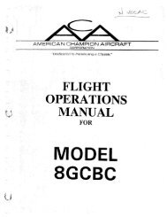
Wing Arca (sq. ft.) . 170.0<br />
Min. Turning Radius (ft.)<br />
(from pivot point to wingtip) 31.0<br />
,‘.-..<br />
.. .<br />
!<br />
THREE VIEW<br />
Figure 1-1<br />
REPORT: VB-930<br />
1-2<br />
ISSUED: NOVEMBER 30,1978
Pl’IPEIP AlHCRAFT COHYORATION<br />
PA-28RT-201, ARROW IV<br />
SECTION 1<br />
GENERAL<br />
1.3 ENGINES<br />
(a) Number of Engines<br />
(b) Engine Manufacturer<br />
(c) Engine Model Number<br />
(d) Rated Horsepower<br />
(e) Rated Speed (rpm)<br />
(f) Bore (in.)<br />
(g) Stroke (in.)<br />
(h) Displacement (CU. in.)<br />
-. (i) Compression Ratio<br />
_, (i) Engine Type<br />
1 I<br />
Lycoming<br />
10-360-C I C6 I<br />
200<br />
2700<br />
5.125<br />
4.375<br />
36 I<br />
8.5: 1<br />
Four Cylinder, Direct<br />
Drive, Horizontally .<br />
Opposed. Air Cooled<br />
and Fuel Injected<br />
><br />
1.5 PROPELLERS<br />
McCAULEY<br />
(a) Number of Propellers<br />
(b) Propeller Manufacturer<br />
(c) Blade Model<br />
(d) Number qf Blades<br />
(e) Hub Model<br />
(f) Propeller Diameter (in.)<br />
(I) .Maximum<br />
(2) Minimum<br />
(8) Propeller Type<br />
1<br />
McCauley<br />
90DHA- 16<br />
2<br />
B2D34C2 13<br />
74<br />
73<br />
Constant Speed,<br />
Hydraulically Actuated<br />
U<br />
2)<br />
I<br />
ISSUED: NOVEMBER 30, 1978<br />
REVISED: JULY 29. 19811<br />
REPORT: VB-930<br />
1-7
GENERAL<br />
._--- -<br />
PA-28RT-201, ARRÖ W IV<br />
HARTZELL<br />
(a) Number of Propellers<br />
(b) Propeller Manufacturer<br />
(c) Blade Model<br />
(d) Number of Blades<br />
(e) Hub Model<br />
(f) Propeller Diameter (in.)<br />
(1) Maximum<br />
(2) Minimum<br />
(g) Propeller Type<br />
1<br />
H artzell<br />
F7666A-2R<br />
2<br />
HC-CZYK-l( )F<br />
74<br />
72<br />
Constant Speed,<br />
Hydraulically Actuated<br />
i<br />
I<br />
j<br />
1.7 FUEL<br />
(a) Fuel Capacity (U.S. gal.) (total)<br />
(b) Usable Fuel (U.S. gal.) (total)<br />
(c) Fuel Grade, Aviation<br />
(I) Minimum Octane<br />
(2) Specified Octane<br />
(3) Alternate Fuels<br />
77<br />
72<br />
100/130 - Grta<br />
100 - Green,<br />
100 LL - Blue or<br />
lOO/ 130 - Green<br />
Refer to latest revision<br />
Of LyCOUlillg SeNiCe<br />
<strong>Instruction</strong> 1070<br />
I<br />
1.9 OIL<br />
(a) Oil Capacity (U.S. qts.)<br />
(b) Oil Specification<br />
(c) Oil Viscosity<br />
8<br />
Refer to latest issue<br />
of Lycoming Service<br />
<strong>Instruction</strong> 1014 )<br />
Refer to Section 8 -<br />
Paragraph 8.19<br />
., .<br />
i<br />
I<br />
: REPORT: VB-930<br />
! 1-4<br />
ISSUED: NOVEMBER 30,1978
PIPER AIRCRAFT CORPORATION<br />
PA-28RT-201, ARRO W IV<br />
SECTION. 1<br />
GENERAL '<br />
1.11 MAXIMUM WEIGHTS<br />
(a) Maximum Takeoff Weight (lbs.)<br />
(b) Maximum Landing Weight (lbs.)<br />
(c) Maximum Weights in Baggage<br />
Compartment<br />
2750<br />
2750<br />
200<br />
1.13 STANDARD AIRPLANE WEIGHTS*<br />
(a) Standard Empty Weight (lbs.):<br />
Weight of a Standard airplane including<br />
unusable fuel, full Operating fluids and<br />
full oil.<br />
(b) Maximum Useful Load (lbs.): The<br />
difference between the Maximum<br />
Takeoff Weight and the Standard<br />
Empty Weight.<br />
1627<br />
1123<br />
1.15 BAGGAGE SPACE<br />
(a) Compartment Voiume (Cu. ft.)<br />
(b) Entry Width (in.)<br />
(c) Entry Height (in.)<br />
24<br />
22<br />
20<br />
1.17 SPECIFIC LOADINGS<br />
(a) Wing Loading (Ibs. per sq. ft.)<br />
(b) Power Loading (lbs. per hp)<br />
16.18<br />
13.75<br />
*These values are approximate and vary from one aircraft to anothcr. Refcr<br />
to Figure 6-5 for the Standard Empty Weight value and the Useful Load<br />
value to be used for C.G. calculations for the aircraft specified.<br />
ISSUED: NOVEMBER 30,1978<br />
REPORT: VB-930<br />
1-5
Sir;LIlUN 1<br />
GENERAL<br />
rxnn n a n L n n r A LWRL wnraaa~~v<br />
PA-28RT-201, ARROW IV<br />
1.19 SYMBOLS, ABBREVIATIONS AND TERMINOLOGY<br />
ihe following definitions are of Symbols, abbreviations and terminology<br />
used throughout the handbook and those which may be of added<br />
operationai significance to the Pilot.<br />
(a) General Airspeed Terminology and Symbols<br />
CAS<br />
KCAS<br />
GS<br />
IAS<br />
KIAS<br />
M<br />
TAS<br />
VA<br />
VFE<br />
Calibrated Airspeed means the indicated<br />
Speed of an aircraft, corrected for Position<br />
and instrument error. Calibrated airspeed<br />
is equai to true airspeed in Standard<br />
atmosphere at sea leveL<br />
Caiibrated Airspeed expressed in "Knots."<br />
Ground Speed is the Speed of an airplane<br />
relative to the ground.<br />
Indicated Airspeed is the Speed of an akcraft<br />
as shown On the airspeed indicator<br />
when corrected for instrument error. IAS<br />
values published in this handbook assume<br />
Zero instrument error.<br />
Indicated Airspeed expressed in "Knots."<br />
Mach Number is the ratio of true airspeed<br />
to the Speed of sound.<br />
True Airspeed is the airspeed of an airplane<br />
relative to undisturbed air which is the<br />
CAS corrected for altitude, temperature<br />
and compressibility.<br />
Maneuvering Speed is the maximum speed<br />
at which application of full available<br />
aerodynamic control will not overstress the<br />
airplane.<br />
Maximum Flap Extended Speed is the<br />
highest Speed permissible with wing flaps<br />
in a prescribed extended Position.<br />
REPORT: VB-930<br />
* 1-6<br />
ISSUED: NOVEMBER 30,1978
PIPER AIRCRAFT CORPORATION SECTIOM 1<br />
PA-28RT-201, ARRO W IV<br />
GENERAL<br />
VLE<br />
Maximum Landing Gear Extended Speed<br />
is the maximum Speed at which an aircraft<br />
can be safely flown with the landing gear<br />
extended.<br />
VLO<br />
Maximum Landing Gear Operating Speed<br />
is the maximum Speed at which the landing<br />
gear can be safely extended or retracted.<br />
VNE/MNE<br />
Never Exceed Speed .or Mach Number is<br />
the Speed limit that may not be exceeded at<br />
any time.<br />
VNO<br />
Maximum Structural Cruising Speed is the<br />
Speed that should not be exceeded except<br />
in smooth air and then only with caution.<br />
vs<br />
Stalling Speed or the minimum steady<br />
* flight Speed at which the airplane is controllable.<br />
vso<br />
vx<br />
Stalling Speed or the minimum steady<br />
flight Speed at which the airplane is controllable<br />
in the landing configuration.<br />
Best Angle-of-Climb Speed is the airspeed<br />
which delivers the greatest gain of altitude<br />
in the shortest possible horizontal distance.<br />
6, ,<br />
thr'<br />
VY<br />
Best Rate-of-Climb Speed is the airspeed<br />
which delivers the greatest gain in altitude<br />
in the shortest possible time.<br />
1<br />
b.<br />
ISSUED: NOVEMBER 30,1978<br />
REPORT: VB-930<br />
.L)
GENEKAL l'A-ZöKl-ZU1, AKKUW 1V<br />
(b) Meteorological Terminology<br />
- . .<br />
ISA<br />
International Standard Atmosphere in<br />
which: ihe air is a dry perfect gas; The<br />
temperature at sea level is 15O Celsius (59"<br />
Fahrenheit); The pressure at sea level is<br />
29.92 inches Hg (1013 mb); The temperature<br />
gradient from sea level to the altitude<br />
at which the temperature is -56.5OC<br />
(-69.7"F) is -0.00198°C (-0.003566OF) per<br />
foot and Zero above that altitude.<br />
.<br />
I<br />
i<br />
OAT<br />
Indicated<br />
'Pressure Altitude<br />
Pressure Altitude<br />
Station Pressure<br />
Wind<br />
Outside Air Temperature is the free air<br />
static temperature, obtained either from<br />
inflight temperature indications or ground<br />
meteorological sources, adjusted for instrument<br />
error and compressibility effects.<br />
The number actually read from an<br />
altimeter when the barometnc subsde has<br />
been set to 29.92 inches of mercury (1013<br />
millibars).<br />
Altitude measured from Standard sea-level<br />
pressure (29.92 in. Hg) by a pressurc or<br />
barometnc altimeter. It is the indicated<br />
pressure altitude corrected for Position and<br />
instrument error. In this handbook,<br />
altimeter instrument crrors are assumed<br />
to be Zero.<br />
Actual atmospheric pressure at field<br />
elevation.<br />
The wind velocities recorded as variables<br />
on the Charts of this handbook are to be<br />
under,stood as the headwind or tailwind<br />
components of the reported Winds.<br />
I<br />
--. '.<br />
REPORT: VB-930<br />
1 -8<br />
ISSUED: NOVEMBER 30,1978<br />
I
PIPER AIRCRA& 1 C'OHPO R ATI Oh'<br />
PA-28RT-201, ARRO W IV<br />
SECTION 1<br />
GENERAL<br />
(c) Power Terminology<br />
Takeoff Power<br />
Maximum Continuous<br />
Power<br />
Maximum Climb<br />
Power<br />
Maximum Cruise<br />
Power<br />
Maximum power permissible for takeoff.<br />
Maximum power permissible continuously<br />
during flight.<br />
Maximum power permissible during<br />
climb.<br />
Maximum power permissible during.<br />
cruise.<br />
P<br />
(d) Engine Instruments<br />
EGT Gauge<br />
Exhaust Gas Temperature Gauge<br />
(e) Airplane Performance and <strong>Flight</strong> Planning Terminology<br />
Climb Gradient<br />
Demonstrated<br />
Crosswind<br />
Velocity<br />
The demonstrated ratio of the changc in<br />
height during a Portion of a climb, to the<br />
horizontal distance traversed in the Same<br />
time interval.<br />
The demonstrated crosswind velocity is the<br />
velocity of the crosswind component for<br />
which adequate control of thc airplane<br />
during takeoff and landing was actuaiiy<br />
demonstrated during ceriification tests.<br />
Accelerate-Sto p The distance required to accelerate an air-<br />
Distance plane to a specified Speed and, assuming ,<br />
failure of an engine at tht instant that specd<br />
is attained, to bring the airplane to a stop.<br />
MEA<br />
Route Segment<br />
Minimum en route IFR aititude.<br />
A pan of a route. Each end of that part is<br />
identified by: (I) a geographical location;<br />
or (2) a Point at which a definite radio fnc<br />
can be estabiished.<br />
ISSUED: NOVEMBER 30,1978<br />
REPORT: VB-930<br />
1-9
1rLK AIKLKAP I LUKYUKAllON<br />
PA-28RT-201, ARROW IV<br />
(f) Weight and Balance Terminology<br />
Reference Datum<br />
Station<br />
Moment<br />
Center of Gravity<br />
(C.G.)<br />
C.G. Arm<br />
C.G. Limits<br />
. ,. Usable Fuel<br />
Unusabie Fuel<br />
Standard Empty<br />
Weight<br />
An imaginary vertical plane from which all<br />
horizontal distances are measured for<br />
balance purposes. ,<br />
A location along the airplane fuselage<br />
usually given in terms of distance.from the<br />
reference datum.<br />
ihe horizontal distance from the reference<br />
datum to the Center of gravity (C.G.) of an<br />
item.<br />
The product of the weight of an item multiplied<br />
by its arm. (Moment divided by a<br />
constant is used to simplify balance calculations<br />
by reducing the number of digits.)<br />
The point at which an airplane would<br />
balance if suspended. Its distance from the<br />
reference datum is found by dividing the<br />
total moment by the total weight of the<br />
airplane.<br />
The arm obtained by adding the airplane's<br />
individual moments and dividing the sum<br />
by the total weight.<br />
The extreme Center of gravity locations<br />
within which the airplane must be operated<br />
at a given weight.<br />
Fuel available for flight planning.<br />
Fuel remaining after a runout test has been<br />
completed in accordance with governmental<br />
regulations.<br />
Weight of a Standard airplane including<br />
unusable fuel, full Operating fluids and full<br />
oil.<br />
(<br />
>. .<br />
REPORT: VB-930<br />
1-10<br />
ISSUED: NOVEMBER 30,1978
PIPER AIRCRAFT CORPORATION SECTION 1<br />
PA-28RT-201, ARRO W IV<br />
GENERAL<br />
Basic Empty<br />
Weight<br />
Payload<br />
Useful Load<br />
Maximum Ramp<br />
Weight<br />
Maximum<br />
Takcoff Weight<br />
Maximum<br />
Landing Weight<br />
Maximum Zero<br />
Fuel Weight<br />
Standard empty weight plus optional<br />
equipment.<br />
Weight of occupants, cargo and baggage.<br />
Difference between takeoff weight, or<br />
ramp weight if applicable, and basic empty<br />
weight.<br />
Maximum weight approved for ground<br />
maneuver. (It includes weight of Start, taxi<br />
and run up fuel.)<br />
Maximum weight approved for the Start of<br />
the takeoff run.<br />
Maximum weight approved for the landing<br />
touchdown.<br />
Maximum weight exclusive of usable fuel.<br />
6.. ,<br />
ISSUED: NOVEMBER 30, 1978<br />
REPORT: VB-930<br />
1-11
SECTION .I<br />
GENERAL<br />
PiPEH ALRCRAFT CORPORATION<br />
PA-28RT-201, ARROW IV<br />
1.21 CONVERSION FACTORS<br />
M ULTIPLY<br />
acres<br />
atmospheres (atm)<br />
bars (bar)<br />
British Thermal Unit (BTU)<br />
centimeters (cm)<br />
' centimeters of mercury at<br />
. 0°C (cm Hg)<br />
centimeters per second<br />
,' fcm/ sec-)<br />
cubic centimeters (cm<br />
BY<br />
0.4047<br />
43560<br />
0.001 5625<br />
76<br />
29.92<br />
1.0133<br />
1.033<br />
14.70<br />
2116<br />
0.98692<br />
14.503768<br />
0.2519958<br />
0.3937<br />
0.032808<br />
0.01316<br />
0.3937<br />
0.1934<br />
27.85<br />
135.95<br />
0.032808<br />
1.9685<br />
0.02237<br />
0.03381<br />
0.06102<br />
3.531 x 10 -5<br />
0.00 1<br />
2.642 x 10 -'<br />
TO OBTAIN<br />
ha<br />
sq. ft.<br />
sq. mi.<br />
cm Hg<br />
in. Hg<br />
bar<br />
kg/cm 2<br />
Ib./sq. in.<br />
lb./sq. ft.<br />
atm<br />
lb./sq. in.<br />
kg-cal<br />
in.<br />
ft<br />
atm<br />
in. Hg<br />
Ib./sq. in.<br />
lb./sq. ft.<br />
kglm<br />
ft. / sec.<br />
ft. / min.<br />
mPh<br />
fl. 02.<br />
CU. in.<br />
CU. ft.<br />
1<br />
U.S. gal.<br />
; REPORT: VB-930<br />
1-12<br />
ISSUED: NOVEMBER 30,1978
M U LTIPLY<br />
cubic feet (CU. ft.)<br />
BY<br />
28317<br />
0.0283 17<br />
1728<br />
0.037037<br />
7.48 1<br />
28.32<br />
TO OBTAIN<br />
cm 3<br />
m3<br />
CU. in.<br />
CU. yd. . .<br />
u.s; gal. '<br />
1<br />
, ,,.,- .<br />
'<br />
cubic feet per minute<br />
(CU. ft. / min.)<br />
SLCi’iON 1<br />
GENERAL<br />
YiYEH AIHCRAFT CORPORATION<br />
PA-28RT-201, ARROW IV<br />
MULTIPLY<br />
feet (ft.)<br />
feet per minute<br />
(ft./ min.)<br />
feet per second<br />
(ft. / sec.)<br />
foot-Pounds (ft.-lb.)<br />
foot-Pounds per minute<br />
(ft.-lb./ min.).<br />
foot-Pounds per second<br />
(ft.-lb./sec.)<br />
BY<br />
30.48<br />
0.3048<br />
12<br />
0.33333<br />
0.060606 1<br />
1.894 x 10 -4<br />
1.645 x 10 -4<br />
0.01 136<br />
0.0 1829<br />
0.508<br />
0.00508<br />
0.6818<br />
1.097<br />
30.48<br />
0.5921<br />
0.138255<br />
3.24 x 10 -4<br />
3.030 x 10 -5<br />
1.818 x 10 -5<br />
TO OBTAIN<br />
cm<br />
m<br />
in.<br />
Yd.<br />
rod<br />
mi.<br />
NM<br />
mph ,--<br />
km/hr. L.<br />
cm/ sec.<br />
m/ sec.<br />
mPh<br />
km/ hr.<br />
an/ sec.<br />
kts.<br />
m-kg<br />
kg-cal<br />
gallons, Imperial<br />
(Imperial gal.)<br />
gallons, U.S. dry<br />
(U.S. gal. dry)<br />
277.4<br />
1.20 1<br />
4.546<br />
268.8<br />
1.556 x 10 -1<br />
1.164<br />
4.405<br />
CU. in.<br />
U.S. gal.<br />
1<br />
CU. in.<br />
CU. ft.<br />
U.S. gal.<br />
1<br />
J<br />
REPORT: VB-930<br />
1-14<br />
ISSUED: NOVEMBER 30,1978
PIPEH AIHCRAE'T CUPPOWATION<br />
PA-28RT-201, ARRO W IV<br />
SECTION 1<br />
GENERAL<br />
MULTIPLY BY TO OBTAIN<br />
gallons, U.S. liquid<br />
(U.S. gal.)<br />
23 1<br />
0.1337<br />
4.951 x 10 -3<br />
3785.4<br />
3.785 x 10 -3<br />
3.785<br />
0.83268<br />
128<br />
CU. in.<br />
CU. ft.<br />
CU. yd.<br />
cm 3<br />
m3<br />
1<br />
Imperial gal.<br />
fl. 02.<br />
I '<br />
gailons per acre<br />
(gai./ acre)<br />
9.353 I/ha<br />
grams per centimeter<br />
(s/ cm)<br />
grams per cubic<br />
centimeter (g/cm 3)<br />
0.00 1<br />
0.3527<br />
2.205 x 10 -3<br />
0.1<br />
6.721 x 10 -2<br />
5.60k x 10 -3<br />
1000<br />
0.03613<br />
62.43<br />
kg<br />
02. avdp.<br />
Ib.<br />
kg/ m<br />
Ib./ft.<br />
Ib./in.<br />
kg/m<br />
lb./cu. in.<br />
Ib./cu. ft.<br />
hectares (ha) 2.47 1<br />
107639<br />
10000<br />
acres<br />
sq. ft.<br />
m2<br />
'<br />
1" - j<br />
horsepower (hp)<br />
33000<br />
550<br />
76.04<br />
1.014<br />
ft.-lb./ min.<br />
ft.-lb. / sec.<br />
m-kg/ sec.<br />
metric hp<br />
horsepower, metric<br />
75<br />
0.9863<br />
inches (in.) 25.40<br />
2.540<br />
0.0254<br />
0.08333<br />
0.027777<br />
m-kg/sec.<br />
hP<br />
mm<br />
cm<br />
m<br />
ft.<br />
Yd.<br />
ISSUED: NOVEMBER 30, 1978<br />
REPORT: VB-930<br />
1-15
GENERAL<br />
PA-28RT-201, ARRO W IV<br />
M ULTIPLY BY TO OBTAIN<br />
inches of mercury at O°C<br />
(in. Hg)<br />
0.033421<br />
0.49 12<br />
70.73<br />
345.3<br />
2.540<br />
25.40<br />
atm<br />
lb./sq. in.<br />
1b.lsq. ft.<br />
kg/m<br />
cm Hg<br />
mm Hg<br />
inch-Pounds (in.-lb.)<br />
0.01 1521 m-kg<br />
kilograms (kg)<br />
kilogram-calories<br />
(kg-cal)<br />
2.204622<br />
35.27<br />
1000<br />
3.9683<br />
3087<br />
426.9<br />
lb.<br />
02. avdp.<br />
g<br />
BTU<br />
ft.-lb.<br />
m-kg<br />
kilograms per cubic meter<br />
(kg/m 3,<br />
kilograms per hectare<br />
(kg/ ha)<br />
kilograms per square<br />
centimeter (kg/cm 2)<br />
kilograms per square<br />
meter (kg/m 2)<br />
0.06243<br />
0.001<br />
lb./cu. ft.<br />
g/cm ’<br />
0.892 lb. / acre<br />
0.9678<br />
28.96<br />
14.22<br />
2048<br />
atm<br />
in. Hg<br />
lb./sq. in.<br />
lb./sq. ft.<br />
2.896 x 10 -3 in. Hg<br />
1.422 x 10 -3 lb./sq. in.<br />
0.2048 lb./sq. ft.<br />
!<br />
kilometers (km) 1 x 10⁻⁵ cm<br />
3280.8 ft.<br />
0.6214 mi.<br />
0.53996 NM<br />
i<br />
REPORT: VB-930<br />
1-16<br />
ISSUED: NOVEMBER 30,1978
MULTIPLY<br />
BY<br />
TO OBTAIN<br />
kilometers per hour<br />
(km / hr.)<br />
0.91 13<br />
58.68<br />
0.53996<br />
0.6214<br />
0.27778<br />
16.67<br />
ft. / sec.<br />
ft. / min.<br />
kt<br />
mPh<br />
m /sec.<br />
m/ min.<br />
knots (kt)<br />
1<br />
1.689<br />
1.1516<br />
1.852<br />
5 1.48<br />
nautical mph<br />
ft./sec.<br />
statute mph<br />
km/ hr.<br />
m/ sec.<br />
liters (1)<br />
1000<br />
6 1.02<br />
0.0353 1<br />
33.814<br />
0.2641 72<br />
0.2200<br />
1.05669<br />
cm’<br />
CU. in.<br />
CU. ft.<br />
fl. 02.<br />
U.S. gaL<br />
Imperial gal.<br />
9t.<br />
liters per hectare<br />
(1/W<br />
13.69<br />
0.107<br />
fl. oz./acre<br />
gal. / acrt<br />
liters per second<br />
(1/sec.)<br />
2.12<br />
CU. ft./min.<br />
/<br />
meters (m)<br />
39.37<br />
3.280840<br />
1.0936<br />
0.198838<br />
6.214 x 10 -4<br />
5.3996 x 10 -4<br />
in.<br />
ft.<br />
Y d.<br />
rod<br />
mi.<br />
NM<br />
meter-kilogram<br />
(m-W<br />
7.23301<br />
86.798<br />
ft.-lb.<br />
in.-lb.<br />
., meters per minute<br />
i<br />
(mlmin.)<br />
0.06<br />
km/ hr.<br />
ISSUED: NOVEMBER 30,1978<br />
REPORT: VB-930<br />
1-17
SECTION i<br />
GENERAL<br />
PlPEH AIHCKAFT CORPORATION<br />
PA-28RT-201, ARROW IV<br />
MULTIPLY BY TO OBTAIN<br />
meters per second<br />
(mlsec.)<br />
3.280840<br />
196.8504<br />
2.237<br />
3.6<br />
ft. I sec.<br />
ft. I min.<br />
mPh<br />
km/ hr.<br />
microns<br />
3.937 x 10 -5 in.<br />
miles, statute (mi.)<br />
5280<br />
1.6093<br />
1609.3<br />
0.8684<br />
ft.<br />
km<br />
m<br />
NM<br />
miles per hour (mph) 44.7041<br />
4.470 x 10 -1<br />
I .467<br />
88<br />
1.6093<br />
0.8684<br />
cml sec.<br />
m/sec.<br />
ft./sec.<br />
ft./ min.<br />
km/ hr.<br />
kt<br />
miles per hour Square<br />
(mlhr. sq.1<br />
2.151 ft./sec. sq.<br />
millibars 2.953 x 10 -2 in. Hg<br />
millimeters (mm) 0.03937 in.<br />
millimeters of mercury at<br />
O°C (mm Hg)<br />
nautical miles (NM) 6080<br />
1.1516<br />
1852<br />
1.852<br />
0.03937 in. Hg<br />
" .<br />
ft.<br />
statute mi.<br />
m<br />
km<br />
Ounces, avdp. (oz. avdp.) 28.35<br />
16<br />
g<br />
dr. avdp.<br />
I<br />
\<br />
REPORT: VB-930<br />
1-18<br />
ISSUED: NOVEMBER 30,1978
PIPER AIRCRAFT CORPORATION SECTION 1<br />
PA-28RT-201, ARRO W IV<br />
GENERAL<br />
MULTIPLY<br />
BY TO OBTAIN 5 :<br />
Ounces, fluid (fl. 02.)<br />
Ounces, fluid per acre<br />
(fl. oz./acre)<br />
Pounds (Ib.)<br />
Pounds pcr acre<br />
(lb. I acre)<br />
Pounds per cubic foot<br />
(lb./cu ft.)<br />
pounds per cubic inch<br />
(lb./cu in.)<br />
Pounds per Square foot<br />
(lb./sq. ft.)<br />
8<br />
29.57<br />
1.805<br />
0.0296<br />
0.0078<br />
0.073<br />
0.453592<br />
453.6<br />
3.108 x 10 -2<br />
1.121<br />
16.02<br />
1728<br />
27.68<br />
0.1414<br />
4.88243<br />
4.725 x 10 -4 . . ..<br />
dr. fl.<br />
cm 3<br />
CU in.<br />
1<br />
U.S. gal.<br />
l/ha<br />
kg<br />
g<br />
slug<br />
lb./cu. ft.<br />
glcm<br />
in. Hg<br />
kg/m<br />
atm<br />
-,<br />
I'<br />
Pounds per Square inch 5.1715<br />
(Psi or lb./sq. in.) 2.036<br />
0.06804<br />
0.0689476<br />
703.1<br />
cm Hg<br />
in. Hg<br />
atm<br />
bar<br />
kg/m<br />
J<br />
quart, U.S. (qt.) 0.94635<br />
57.749<br />
1<br />
CU. in.<br />
radians 57.30<br />
0.1592<br />
deg. (arc)<br />
rev.<br />
radians per second<br />
(radiansl sec.)<br />
57.30<br />
0.1592<br />
9.549<br />
deg./sec.<br />
rev. / sec.<br />
rPm<br />
d<br />
h'<br />
i<br />
ISSUED: NOVEMBER 30,1978<br />
REPORT: VB-930<br />
i-*n
GENERAL<br />
------- --------.L-.V..<br />
PA-28RT-201, ARRO W IV<br />
MULTI PLY<br />
BY<br />
TO OBTAIN<br />
revolutions (rev.)<br />
6.283<br />
radians<br />
revolutions per minute<br />
(rpm or rev./min.)<br />
0.1047<br />
radiansl sec.<br />
revolutions per second<br />
(rev. /sec.)<br />
6.283<br />
radianslsec.<br />
rod<br />
\<br />
16.5<br />
5.5<br />
5.029<br />
ft.<br />
Yd.<br />
m<br />
\<br />
slug<br />
32.174<br />
Ib.<br />
square centimeters<br />
(cm 2,<br />
0.1550<br />
0.00 1076<br />
sq. in.<br />
sq. ft.<br />
Square feet (sq. ft.)<br />
929<br />
0.092903<br />
144<br />
0.1111<br />
2.296 x 10 -5<br />
cm 2<br />
m2<br />
sq. in.<br />
sq. 'yd.<br />
acrts<br />
I<br />
,J<br />
Square inches (sq. in.) '<br />
6.45 16<br />
6.944 x 10 -3<br />
cm 2<br />
sq. ft.<br />
Square kilometers<br />
(km 9<br />
0.3861<br />
sq. mi.<br />
Square meters (m 2)<br />
\<br />
10.76391<br />
1.196<br />
0.0001<br />
sq. ft.<br />
sq. yd.<br />
ha<br />
Square miles (sq. mi.)<br />
2.590<br />
640<br />
km 2<br />
acrcs<br />
Square rods (sq. rods)<br />
30.25<br />
sq. yd.<br />
square yards (sq, yd.)<br />
0.8361<br />
9<br />
0.0330579<br />
m2<br />
sq. ft.<br />
sq. rods<br />
REPORT: VB-930<br />
1-20<br />
ISSUED: NOVEMBER 30,1978
PIPER AIRCRAFT CORPORATION<br />
PA-28RT-201, ARROW IV<br />
SECTION I<br />
GENERAL<br />
M ULTIPLY<br />
yards (yd.)<br />
BY<br />
0.9 144<br />
3<br />
36<br />
0.181818<br />
TO OBTAIN<br />
m<br />
ft.<br />
in.<br />
rod<br />
, )’<br />
j<br />
ISSUED: NOVEMBER 30,1978<br />
REPORT: VB-930<br />
1-21
,i<br />
..
TABLE OF CONTENTS<br />
SECTION 2<br />
LIMITATIONS<br />
’- Paragraph<br />
No.<br />
2.1<br />
2.3<br />
2.5<br />
2.7<br />
2.9<br />
2.1 1<br />
2.13<br />
(’ 2.15<br />
2.17<br />
2.19<br />
2.21<br />
2.23<br />
2.25.<br />
General . . . . . . . . . . . . . . . . . . . . . . . . . . . . . . . . . . . . . . . . . .<br />
Ainpeed Limitations ...... . Airspeed Indicator Markings Power Plant Limitations ........ . Power Plant Instrument Markings Weight Limits.. . ..... .. Center of Gravity Limits.. ...... ....... ........ .....<br />
Maneuver Limits .... <strong>Flight</strong> Load Factors.. Types of Operations ,<br />
Fuel Limitations Noise Level ........ ........... ............ ....... .<br />
Placards.. . . . . . . . . . . . . . . . . . . . . . . . . . . . . . . . . . . . . . ?. .<br />
Page<br />
No.<br />
2-1<br />
2-1<br />
2-2<br />
2-3<br />
24 . ,<br />
2-5 .:<br />
2-5<br />
2-5<br />
2-6<br />
2-6<br />
2-6<br />
2-7<br />
2-8<br />
I<br />
. .<br />
REPORT: VB-930<br />
2-1
PIPE# AIRCRAFT CORPORATION SECTION 2<br />
PA-28RT-201, ARRO W IV<br />
LIMITATIONS<br />
SECTION 2<br />
LIMITATIONS<br />
c<br />
2.1 GENERAL<br />
This section provides the "FAA Approved" Operating limitations,<br />
instrument marfings, color coding and basic placards necessary for the Safe<br />
Operation of the airplane and its Systems.<br />
Mtations associated with those opuonai Systems and equipment which<br />
rcquire handbook Supplements can be found in Section 9 (Supplements).<br />
_><br />
23 AIRSPEED LIMITATIONS<br />
SPEED KIAS KCAS<br />
Nevcr Exceed Speed (VNE) - Do not exceed<br />
this specd in any Operation.<br />
190 186<br />
I<br />
Maximum Structural Cruising Speed<br />
(WO)- Do not excccd this speed except in<br />
smooth air and then only with caution. 149 148<br />
< .<br />
*1. '<br />
w<br />
'i<br />
Design Maneuvenng Speed (VA) - Do not<br />
make full or abrupt control movements<br />
above this speed.<br />
At 2750 lbs. G.W. 121 121 !<br />
At 1863 lbs. G.W. 96 97 . I<br />
CA UTION<br />
Maneuvenng speed decreases at lighter weight<br />
as the effects of aerodynamic forces become<br />
more pronounced. Linear interpolation may be<br />
used for intermcdiate gross weights. Maneuvering<br />
speed should not be exceeded while operating<br />
in rough air.<br />
ISSUED: NOVEMBER 30,1978<br />
REPORT: VB-930-<br />
--<br />
i
SECTION 2<br />
LIMITATIONS<br />
PIPER AIRCRAFT CORPORATION<br />
PA-28RT-201, ARROW IV<br />
SPEED KIAS KCAS<br />
Maximum Flaps Extended Speed (VFE)-<br />
Do not exceed this speed with the flaps f<br />
1.<br />
extended. 108 104<br />
Maximum Landing Gear Extension Speed -<br />
Do not exceed this speed when extending<br />
the landing gear. 130 130<br />
Maximum Landing Gear Retraction Speed -<br />
Do not exceed this speed when retracting<br />
the landing gear. 109 109<br />
3<br />
Maximum Landing Gear Extended Speed<br />
(VLE)- Do not exceed this speed with the<br />
landing gear extended. 130 130<br />
2.5 AIRSPEED INDICATOR MARKINGS<br />
MARKING<br />
Red Radial Line (Never Exceed)<br />
Yellow Arc (Caution Range - Smooth<br />
Air Only) .<br />
Green Arc (Normal Operating Range)<br />
White Arc (Flap Down)<br />
IAS<br />
190 KTS<br />
149 KTS to<br />
190 KTS<br />
58 KTS to<br />
149 KTS<br />
53 KTS to \<br />
108 KTS . 1<br />
REPORT: VB-930<br />
2-2<br />
ISSUED: NOVEMBER 30,1978
PIPER AIRCRAFT CORYOXATION SECTION 2<br />
PA-28RT-201. ARROW IV<br />
LIMITATIONS<br />
2.7 PO WER PLANT LIMITATIONS<br />
(a) Number of Engines<br />
I<br />
(b) Engine Manufacturer<br />
(c) Engine Model No.<br />
(d) Engine Operating Limits<br />
(1) Maximum Horsepower<br />
(2) Maximum Rotation Speed (RPM)<br />
(3) Maximum Oil Temperature<br />
(e) Oil Pressure<br />
I<br />
Minimum (red line)<br />
\\ Maximum (red line)<br />
(0 Fuel Pressure<br />
Minimum (red line)<br />
Maximum (red line)<br />
(g) Fuel Grade (minimum octane)<br />
(h) Number of Propellers<br />
(i) Propeller Manufacturer<br />
Ci) Propeller Hub and Blade Model<br />
(1) McCauley<br />
(2) Hartzell<br />
i<br />
(k) Propeller Diameter<br />
(I) McCauley<br />
Minimum<br />
Maximum<br />
(2) Hartzell<br />
Minimum<br />
Maximum<br />
(1) Blade Angle Limits<br />
(I) McCauley<br />
Low Pitch Stop<br />
High Pitch Stop<br />
(2) Hartzell<br />
Low Pitch Stop<br />
High Pitch Stop<br />
1<br />
Lycoming<br />
10-360-C1C6 I<br />
200<br />
2700<br />
245" F<br />
25 PSI<br />
100 PSI I<br />
14 PSI<br />
45 PSI<br />
lOO/ 130 - Green<br />
1<br />
McCauley or Hartzell<br />
B2D34C213/90DHA-16<br />
HC-C2YK-l( )F/<br />
F7666A-2R<br />
73<br />
74<br />
72<br />
74<br />
12.5 f 0.2"<br />
27.5 f 0.5"<br />
14.0 +, 0.2"<br />
29.0 t 2.0"<br />
ISSUED: NOVEMBER 30,1978<br />
REVISED: JULY 29,1980<br />
REPORT: VB-930<br />
2-3
LIMIXAXJONS<br />
YA-ZöKl-201, ARRO W IV<br />
(m) RPM Restrictions (McCauley<br />
Propeller Only)<br />
Avoid Continuous<br />
Operation Between<br />
1500 and 1950 RPM<br />
Below 15 Inches Map.<br />
2.9 POWER PLANT INSTRUMENT MARKINGS<br />
(a) Tachometer<br />
Green Arc (Normal Operating Range)<br />
Red Line (Maximum Continuous<br />
Power)<br />
(b) Oil Temperature<br />
Green Arc (Normal Operating Range)<br />
Red Line (Maximum)<br />
(c) Oil Pressure<br />
Green Arc (Normal Operating Range)<br />
Yellow Arc (Caution Range) (Idle)<br />
Red Line (Minimum)<br />
Red Line (Maximum)<br />
(d) Fuel Pressure<br />
Green Arc (Normal Operating Range)<br />
Red Line (Minimum)<br />
Red Line (Maximum)<br />
500 to 2700 RPM<br />
2700 RPM<br />
75O to 245°F<br />
245O F<br />
60 PSI to 90 PSI<br />
25 PSI to 60 PSI<br />
25 PSI<br />
100 PSI<br />
14 PSI to 45 PSI<br />
14 PSI<br />
45 PSI<br />
I<br />
REPORT: VB-930<br />
2-4<br />
ISSUED: NOVEMBER 30,1978<br />
REVISED: JULY 29,1980
IP#-28HT-201, ARRO W 1V<br />
LIMITATIONS<br />
2.11 WEIGHT LIMITS<br />
(a) Maximum Weight<br />
(b) Maximum Baggage<br />
2750 LBS.<br />
200 LBS.<br />
NOTE<br />
Refer to Section 5 (Performance) for maximum<br />
weight as limited by Performance.<br />
I<br />
2.13 CENTER OF GRAVITY LIMITS<br />
Weight<br />
Pounds<br />
Forward Limit<br />
Inches Aft of Datum<br />
Reanvard Limit<br />
Inches Aft of Datum<br />
2750<br />
2400<br />
90.0 93.0<br />
85.5 93.0<br />
,)<br />
NOTES<br />
Straight line Variation between Points given.<br />
The datum used is 78.4 inches ahead of the<br />
wing leading edge at the intersection of the<br />
straight and tapered section.<br />
1<br />
It is the responsibility of the airplane owner<br />
and the pilot to insure that the airplane is<br />
properly loaded. See Section 6 (Weight and<br />
Balance) for proper loading instructions.<br />
2.15 MANEUVER LIMITS '<br />
No acrobatic maneuvers including Spins approved.<br />
ISSUED: NOVEMBER 30,1978<br />
REPORT: VB-930<br />
2-5
SECTION 2<br />
LIMITATIONS<br />
PIPER AIRCRAFT CORPORATION<br />
PA-28RT-201, ARROW IV<br />
2.17 FLIGHT LOAD FACTORS<br />
(a) Positive Load Factor (Maximum)<br />
(b) Negative Load Factor (Maximum)<br />
3.8 G<br />
No inverted maneuvers<br />
approved<br />
(<br />
2.19 TYPES OF OPERATIONS<br />
The airplane is approved for the following Operations when equipped in<br />
accordance with FAR 91 or FAR 135.<br />
(a) Day V.F.R.<br />
(b) Night V.F.R.<br />
(c) Day I.F.R.<br />
(d) Night I.F.R.<br />
(e) Non Icing<br />
\<br />
2.21 FUEL LIMITATIONS<br />
(a) Total Capacity<br />
(b) Unusable Fuel<br />
The unusable fuel for this airplane has<br />
been determined as 2.5 gallons in each<br />
wing tank in critical flight attitudes.<br />
(c) Usable Fuel<br />
The usable fuel in this airplane has<br />
been determined as 36.0 gallons in each<br />
wing tank.<br />
\ (d) Fuel remaining when the quantity indicators<br />
read Zero cannot be used safely<br />
in flight.<br />
77 U.S. GAL.<br />
5 U.S. GAL.<br />
72 U.S. GAL.<br />
REPORT: VB-930<br />
-,<br />
ISSUED: NOVEMBER 30, 1978
YlYYK AlKLKAb 1 LlJfirUtrAiiui.i<br />
PA-28RT-201, ARRO W 1V<br />
um%. b bW&.<br />
I<br />
LIMITATIONS<br />
2.23 NOISE LEVEL<br />
The noise level of Chis aircraft is 75.5 d B(A).<br />
No determination has been made by the Federal Aviation Administration<br />
that the noise levels of this airplane are or should be acccptable or<br />
unacceptable for Operation at, into, or out of, any airport.<br />
The above Statement not withstanding the noise level stated abovc has<br />
been verified by and approved by the Federal Aviation Administration in<br />
noise level test flights conducted in accordance with FAR 36, Noisc<br />
Standards - Aircraft Type and Ainvorthiness Certification. This aircra’<br />
model is in compliance with all FAR 36 noise Standards applicable to th,<br />
tY Pe-<br />
ISSUED: NOVEMBER 30,1978<br />
REPORT: VB-930<br />
2-7
3bbAlUil L<br />
LIMITATIONS<br />
rlrLK AlKLKAP A<br />
LUKrtJRAAlUll<br />
PA-28RT-201, ARRO W IV<br />
2.25 PLACARDS<br />
In full view of the Pilot:<br />
THIS AIRPLANE MUST BE OPERATED AS A NOR-<br />
MAL CATEGORY AIRPLANE IN COMPLIANCE<br />
WITH THE OPERATING LIMITATIONS STATED<br />
IN THE FORM OF PLACARDS, MARKINGS AND<br />
MANUALS.<br />
THIS AIRCRAFT APPROVED FOR NIGHT I.F.R.<br />
NON-ICING FLIGHT WHEN EQUIPPED IN<br />
1<br />
ACCORDANCE WITH FAR 91 OR FAR 135.<br />
In full view of the Pilot, the following Takeoff and Landing Check Lists<br />
wili be installed:<br />
TAKEOFF CHECK LIST<br />
Fuel on Proper Tank<br />
Electric Fuel Pump - On<br />
Engine Gauges - Checked<br />
Alternate Air - Closed<br />
Seat Backs Erect<br />
Mixture - Set<br />
Propeller - Set<br />
Fasten Belts/ Harness<br />
Flaps - Set<br />
Trim Tab - Set<br />
Controls - Free<br />
Doors - Latched<br />
Air Conditioner - Off<br />
' I<br />
I ;<br />
. .<br />
Fuel on Proper Tank<br />
Scat Backs Erect<br />
Fasten Belts/ Harness<br />
Electric Fuel Pump - On<br />
Mixture - Rich<br />
LANDING CHECK LIST<br />
Propeller - Set<br />
Gear Down<br />
Flaps - Set (White Arc)<br />
Air Conditioner - Off<br />
The "Air Conditioner Off" item in the above Takeoff and Landing<br />
Check Lists is mandatory for air conditioned aircraft only.<br />
On the instrument panel in full view of the Pilot:<br />
MANEUVERING SPEED 121 KIAS<br />
AT 2750 LBS. (SEE A.F.M.)<br />
REPORT: VB-930 ISSUED: NOVEMBER 30,1978<br />
2-8
B'A~?~.X AiHCKAk I' c 0ldk'ciiCt-t i iOi\ SECTION 2<br />
PA-28RT-201, ARROW IV<br />
I,IMITATIONS<br />
/-'<br />
On thc instrurnent panel in full vicw of rhe Pilot:<br />
DEMONSTRATED CROSSWIND COMPONENT 17 KTS<br />
On the instrurnent panel in full view of the pilot:<br />
NO ACROBATIC MANEUVERS.<br />
INC1-UDING SPINS. APPROVED<br />
On the instrurnent panel in full vicw of the pilot:<br />
GEAR DOWN<br />
GEAR UP<br />
EXTENDED<br />
1.70 KlAS (MAX.)<br />
109 KlAS (MAX.)<br />
1.70 KlAS (MAX.)<br />
Near ernergency gear lever:<br />
/--<br />
EMERGEKCY DOWN<br />
Near ernergency gear lever (aircraft equipped with backup gear extender) I<br />
OVE R R I DE ENG AG E D A UTO-EXT-OFF<br />
LOCK PIK ON SlDE<br />
TO ENGAGE OVERRIDE:<br />
PULL 1.EVER FU1.L UP. PUSH LOCK PIK<br />
TO RELEASE OVERRIDE:<br />
PULL. LEVER FULL UP & RELEASE<br />
..-<br />
/<br />
..<br />
Near gear selector switch:<br />
GEAR UP<br />
109 KlAS MAX.<br />
1 DOWN 130 KIAS MAX.<br />
Adjacent to upper door latch:<br />
ENGAGE i.ATCH BEFORE FI.IGHT<br />
ISSI:ED: NOVEMBER 30, 1978<br />
REVISED: JANUARY 31. 1987<br />
REPORT: VB-930<br />
2-9
SECTION 2<br />
LIMITATIONS<br />
PIPER AIRCRAFT CORPORATION<br />
PA-28RT-201, ARROW IV<br />
On the instrument panel in full view of the pilot:<br />
WARNING<br />
TURN OFF STROBE LICHTS WHEN IN<br />
CLOSE PROXIMITY TO GROUND OR<br />
DURING FLICHT THROUGH CLOUD,<br />
FOG OR HAZE.<br />
In full view of the pilot, in the area of the air conditioner controls when<br />
the air conditioner is installed:<br />
WARNING<br />
AIR CONDITIONER MUST BE OFF TO<br />
INSURE NORMAL TAKEOFF CLlMB<br />
PERFORMANCE.<br />
On inside of baggage compartment door:<br />
BAGGAGE MAXIMUM 200 LBS. SEE WEICHT AND<br />
BALANCE DATA FOR BAGGAGE LOADING BE-<br />
TWEEN 150 LBS. AND 200 LBS.<br />
Adjacent to fuel tank filler caps:<br />
FUEL - iOO/ 130 AVlATlON GRADE - MIN. USABLE<br />
CAPACITY 36 GAL.<br />
USABLE CAPACITY TO BOTTOM OF FILLER<br />
NECK INDICATOR 25 GAL.<br />
Above fuel quantity gauges:<br />
FUEL REMAINING WHEN QUANTITY INDICATOR<br />
READS ZERO CANNOT BE USED SAFELY IN<br />
FLICHT.<br />
REPORT: VB-930<br />
2-10<br />
ISSUED: NOVEMBER 30. 1978
PIYER AIRCRAFT CORYORATION<br />
PA-28RT-201, ARROW IV<br />
SECTIt<br />
LIMITATIl<br />
On the instrument panel in full view of the pilot in aircraft<br />
McCauley propeller installations only:<br />
AVOID CONTINUOUS OPERATION BETWEEN<br />
1500 AND 1950 RPM BELOW 15" MANIFOLD<br />
PRESSURE.<br />
On the aft baggage closeout:<br />
MAXIMUM BAGGAGE 200 LBS. NO HEAVY<br />
OBJECTS ON HAT SHELF.<br />
ISSUED: NOVEMBER 30,1978<br />
REPORT VB
TABLE OF CONTENTS<br />
SECTION 3<br />
EMERGENCY PROCEDURES<br />
Paragraph Pa. .<br />
No . No .<br />
3.1<br />
3.3<br />
3.5<br />
3.7<br />
3.9<br />
3.1 1<br />
3.13<br />
3.15<br />
3.17<br />
3.19<br />
3.21<br />
3.23<br />
3.25<br />
3.27<br />
3.29<br />
3.3 1<br />
3.33<br />
General .......................................... 3-1<br />
Emergency Procedures Check List ....................<br />
3-2<br />
Amplified Ernergency Procedures (General) ........... 3-9<br />
Engine Fire Dunng Start ........................... 3-9<br />
Engine Power Loss During Takeoff .................. 3-9<br />
Engine Power Loss In <strong>Flight</strong> ........................ 3-10<br />
Power Off Landing ................................ 3-11<br />
Fire In <strong>Flight</strong> ..................................... 3-13<br />
Loss of Oil Pressure ............................... 3-13<br />
Loss of Fuel Pressure .............................. 3-14<br />
High Oil Temperature .............................. 3-14<br />
Alternator Failure ................................. 3-14<br />
Propeller Overspeed .................................. 3-15<br />
Emergency Landing Gear Extension .................. 3-15<br />
Spin Recovery .................................... 3-16<br />
Open Door ....................................... 3-16<br />
Engine Roughness ................................. 3-16<br />
REPORT: VB-930<br />
3-1
PlPER AIRCRAFT CORPORATION SECTION 3<br />
PA-28RT-201, ARROW IV<br />
EMERGENCY PROCEDURES<br />
SECTION 3<br />
EMERGENCY PROCEDURES<br />
3.1 GENERAL<br />
The recommended procedures for coping with various types G<br />
emergencies and critical Situations are provided by this section. All of the<br />
required (FAA regulations) emergency procedures and those necessary for<br />
the Safe Operation of the airplane as determined by the Operating and design<br />
features of the airplane are presented.<br />
Emergency procedures associated with those optional Systems and<br />
equipment which require handbook Supplements are provided by Section 9<br />
(Supplements).<br />
The first Portion of this section consists of an abbreviated emergency<br />
check list which supplies an action sequence for critical Situations with little<br />
emphasis on the Operation of Systems.<br />
The remainder of the section is devoted to amplified emergency<br />
procedures containing additional information to provide the pilot with a<br />
more complete understanding of the procedures.<br />
These procedures are suggested as the best Course of action for coping<br />
with the particular condition described. but are not a Substitute for sound<br />
judgment and common sense. Since emergencies rarely happen in modet<br />
aircraft. their occurrence is usually unexpected and the best correctiv., '<br />
action rnay not always be obvious. Pilots should familiarize thernselves with<br />
the procedures given in this section and be prepared to take appropriate<br />
üction should an emergency arise.<br />
Most basic emergency procedures. such as power Off landings. are a<br />
normal part olpilot training. Although these emergencies arediscussed here,<br />
this information is not intended to replace such training. but only to provide<br />
a source of rel'erence and review. and to provide information on procedures<br />
which üre not the Same for all aircraft. It is suggested that the pilot review<br />
Standard emcrgency procedures periodically to rernain proficient in them.<br />
ISSGED: NOVEMBER 30. 1978<br />
REPORT: VB-930<br />
3- 1
SECTION 3<br />
PIPER AIRCRAFT CORPORATION<br />
EMERGENCY PROCEDURES<br />
PA-28RT-201, ARROW IV<br />
I<br />
3.3 EMERGENCY PROCEDURES CHECK LIST<br />
ENGINE FIRE DURING START<br />
Starter.. .............................................<br />
Mixture ..............................................<br />
Throttle ...................................................<br />
Electric fuel pump ..........................................<br />
Fuelselector ...............................................<br />
Abandon if fire continues.<br />
ENGINE POWER LOSS DURING TAKEOFF<br />
crank engine<br />
idle Cut-Off<br />
Open<br />
OFF<br />
OFF<br />
lf sufficient runway remains for a normal landing, leave gear down and land<br />
straight ahead.<br />
If area ahead is rough, or if it is necessary to clear obstructions:<br />
Gear selector switch ...........................................<br />
Emergency gear lever (aircraft equipped with<br />
backup gear extender) ......................<br />
If sufficient altitude has been gained to attempt a restart:<br />
Maintain Safe airspeed.<br />
Fuel selector .......................................<br />
UP<br />
.locked in OVERRlDE<br />
ENGAGED Position<br />
Electric fuel pump ......................................<br />
Mixture ............................................<br />
Alternate air ..............................................<br />
Emergency gear lever ...................................<br />
If power is not regained. proceed with power Off landing.<br />
1 ENGINE POWER LOSS IN FLICHT<br />
Fuel selector .......................................<br />
switch to tank<br />
containing fuel<br />
check ON<br />
.check RlCH<br />
OPEN<br />
as required<br />
switch to tank<br />
containing fuel<br />
ON<br />
Electric fuel pump ...........................................<br />
Mixture .................................................. RlCH<br />
Alternate air .............................................. OPEN<br />
Engine gauges ..;..............................<br />
check for indication<br />
of cause of power loss'<br />
If no fuel pressure is indicated. check tank selector Position to be Sure it is on<br />
a tank containing fuel.<br />
REPORT: VB-930<br />
3-2<br />
ISSUED: NOVEMBER 30, 1978<br />
REVISED: JANUARY 31, 1987
YlPEH AIHCHAF'I' CORPORATION SECTION 3<br />
PA-28RT-201, ARROW IV<br />
EMERGENCY PROCEDURES<br />
.<br />
When power is restored:<br />
Alternate air ...........................................<br />
Electric fuel pump ..........................................<br />
lf power is not restored prepare for power Off landing.<br />
Trim for 79 KlAS.<br />
CLOSED<br />
OFF<br />
POWER OFF LANDING<br />
On aircraft equipped with the backup gear extender, lock emergency gear<br />
lever in OVERRlDE ENGAGED Position before airspeed drops to 105<br />
KlAS to prevent the landing gear from free falling.<br />
' )nm for 79 KlAS.<br />
Locate suitable field.<br />
Establish spiral Pattern.<br />
1000 ft. above field at downwind Position for normal landing approach.<br />
When field can easily be easily reached slow to 72 KlAS for shortest landing.<br />
GEAR DOWN EMERGENCY LANDING<br />
Touchdowns should normally be made at lowest possible airspeed with full<br />
flaps.<br />
When committed to landing:<br />
ianding gear selector .....................................<br />
Throttle ................................................... close<br />
Mixture .............................................. idle cut-Off<br />
lgnition ................................................... OFF<br />
Master switch .............................................. OFF<br />
Fuel selector ............................................... OFF<br />
Seat belt and harness.. ....................................... tight<br />
TEAR UP EMERGENCY LANDlNG<br />
~ / J<br />
In the event a gear up landing is required, proceed as follows:<br />
DOWN I<br />
as desired I<br />
Flaps .................................................<br />
Throttle ................................................... close<br />
Mixture .............................................. idle cut-Off<br />
... lgnition switches.. .......................................... OFF<br />
Master switch .............................................. OFF<br />
Fuel selector ............................................... OFF<br />
Seat belt and harness.. ....................................... tight<br />
Contact surface at mini.mum possible airspeed.<br />
ISSUED: NOVEMBER 30,1978<br />
REVISED: JANUARY 31,1987<br />
REPORT: 930<br />
3-3
SECTION 3<br />
EMERCENCY PROCEDURES<br />
PIPER AIRCRAFT CORPORATION<br />
PA-28RT-201, ARROW IV<br />
FIRE IN FLICHT<br />
Source of fire ...............................................<br />
Electrical fire (smoke in cabin):<br />
Master switch ..............................................<br />
Vents .......................................................<br />
Cabin heat .................................................<br />
Land as soon as practicable.<br />
check<br />
OFF<br />
Open<br />
OFF<br />
...<br />
I<br />
i: Engine fire:<br />
Fuel selector ...............................................<br />
Throttle ...............................................<br />
Mixture ..............................................<br />
Electric fuel pump ....................................<br />
Heater and defroster ........................................<br />
Proceed with power Off landing procedure.<br />
OFF<br />
CLOSEL<br />
idle Cut-Off<br />
.check OFF<br />
OFF<br />
LOSS OF OIL PRESSURE<br />
Land as soon as possible and investigate cause.<br />
Prepare for power Off landing.<br />
LOSS OF FUEL PRESSURE<br />
ON<br />
.check on full tank<br />
Electric fuel pump ...........................................<br />
Fuel selector ...................................<br />
REPORT: VB-930<br />
3-4<br />
ISSUED: NOVEMBER 30. 1978
PA-28RT-201, AKKOW IV<br />
EMEKCENCY PROCEDURES<br />
HIGH 011, TEMPERATURE<br />
Land at nearcst airport and investigatc thc problcm.<br />
Yrcparc for powcr ofC landing.<br />
ALTERNATOR FAILURE<br />
Vcrify failure.<br />
Reduce elecirical load as niuch as possiblc.<br />
Altcmator circuit breakers ...........................................................................<br />
Alt switch ..............................................................................<br />
/ ---<br />
check<br />
OFF (for I second),<br />
thcn on<br />
11 no'output:<br />
Alt switch .......................................................................................................<br />
Rcducc electrical load and land as soon as practical.<br />
OFF<br />
II' battery is fully discharged, thc gear will have to be lowcred using the<br />
etncrgency gear extension procedure. Position lights will not illuminate.<br />
-!<br />
'ROPELLER OVEHSPEED<br />
wi<br />
Tiirottle ........................................................................................................<br />
Oil prcssure ..................................................................................................<br />
Prop control .......................................................................<br />
rc tard<br />
check<br />
full DECKEASE rpm,<br />
then set if any<br />
control available<br />
Airspced ......................................................................................................<br />
Throttle ................................................................................<br />
rcduce<br />
as requircd to rcrnain<br />
bclow 2700 rpm<br />
i i<br />
ISSUED: NOVEMIIER 30,1978<br />
REPORT VB-930<br />
3-5
i<br />
I<br />
I<br />
I<br />
! 1<br />
I<br />
SECTION 3 PlPER @CKAFT CORYORATION<br />
EMERGENCY PROCEDURES<br />
PA-28RT-201, ARROW 1V<br />
EMERGENCY LANDING CEAH EXTENSION<br />
Prior io emergency exicnsion procedure:<br />
Masicr swiich ........................................................................................ chcck OP<br />
Circui i breakcrs ............................................................................................ check<br />
Panel lights ................................................................................ OFF (in daytimc)<br />
chcc~<br />
Gear indicator bulbs .....................................................................................<br />
If landing gcar docs not chcck down and lock:<br />
Airspccd ............................................................................<br />
Landing gear selector swiich ..............................................<br />
r~duce below 87 KIAS<br />
g ear DOWN Position<br />
If ge’ar has failed 10 lock down on aircraft equipped with thc backup geai<br />
extender. raise emergency gear lever to “Override Engaged” posiiion.<br />
If gear has siill failed to lock down, move and hold the emergency lever<br />
down to the EMERGENCY DOWN Position.<br />
If gear has still4ailed 10 lock down, yaw ihe airplanc abruptiy from side 10<br />
side with ihe ruddcr.<br />
i<br />
’<br />
.<br />
If the nose gear will not lock down using the above proccdure, slow the<br />
aircraft 10 thc lowesi Safe Speed attainable using ihe lowcst power Setting<br />
required for safc Operation and accomplish the following: ...<br />
Emergency gear lever (On aircraft equipped with<br />
ihe backup gear cxtender) ...................................... “OVERRIDE ENGAGED”‘-’<br />
Landing gear selecior switch .............................................. gear DOWN Position<br />
If landing gear does not check down, rccycle gear ihrough up position, and<br />
ihen select gear DOWN.<br />
)<br />
,j<br />
SPIN RECOVERY<br />
Rudder ........................................................................................... full oppositc to<br />
direciion of roiation<br />
Control whccl ........................................................................... full forward whilc \<br />
neuiraiizing ai~crons ’<br />
idlc<br />
ncutral (wheri roiation siops)<br />
as required 10 smooihly<br />
rcgain levcl flight aitiiude<br />
Throiile. ...........................................................................................................<br />
Ruddcr .....................................................................<br />
Conlrol whecl ..................................................................<br />
OPEN DOOR<br />
If boih upper and sidc latchcs are opcn, ihe door will trail slightly opcn an<br />
and airspceds will bc reduced slighily.<br />
KEPORT: VB-930 ISSUED: NOVEMBER 30,1978<br />
3-6 REVISED: SEPTEMBER 06,1996
PIPER AIRCRAFT CORPORATION SECTION 3<br />
PA-28RT-201, ARROW IV<br />
EMERGENCY PROCEDURES<br />
To close the door in flight:<br />
Slow airplane to 87 KIAS.<br />
Cabin vents ........................................... ;.... close<br />
Storm window.. ............................................ Open<br />
If upper latch is Open.. ...................................... iatch<br />
If side latch is Open ...........................<br />
pul1 on armrcst whiie<br />
moving latch handle to<br />
latched Position<br />
.<br />
..<br />
.<br />
If both latches are Open.. ........................... latch side latch<br />
.,/<br />
',<br />
then top latch<br />
ISSUED: NOVEMBER 30,1978<br />
REPORT VB-930<br />
3-7
!i ..<br />
'.. .<br />
EMERCENCY PROCEDURES<br />
PA-28RT-201, ARROW IV<br />
'I<br />
THIS PAGE INTENTIONALLY LEFT BLANK<br />
i<br />
i<br />
I ,<br />
!/ 3-8<br />
3<br />
I<br />
REPORT: VB-930<br />
ISSUED: NOVEMBER 30,1978
3.5 AMPLIFIED EMERGENCY PROCEDURES (GENERAL)<br />
c<br />
The following paragraphs are presented to supply additional<br />
,' information for the purpose of providing the pilot wiih a more complete<br />
understanding of the recommended Course of action and probable cause of<br />
, an emergency Situation.<br />
... ,<br />
3.7 ENGINE .FIRE DURINC START<br />
Engine fires during start are usually the result of overpriming. The first<br />
ttempt to extinguish the fire is to try to start the engine and draw theexcess<br />
t'uel back into the induction.system.<br />
If a fire is present before the engine has started. move the mixture<br />
control to idle Cut-off. Open the throttle and crank the engine. This is an<br />
attempt to draw the fire back into the engine.<br />
If the engine hasstarted. continue Operating to try to pul1 the fire into the<br />
engine.<br />
In either case (above). if fire continues more than a few seconds, the fire<br />
should be extinguished by the best available external means.<br />
The fuel selector valves should be OFF and the mixture at idle Cut-Off if<br />
an external fire extinguishing method is to be used.<br />
3.9 ENGlNE POWER LOSS DURING TAKEOFF<br />
The proper action to be taken if loss of power occurs during takeoff will<br />
depend on the circumstances of the particular Situation.<br />
If sufficient runway rernains to complete a normal landing. leave the<br />
' landing gear down and land straight ahead.<br />
If the area ahead is rough. or if it is necessary to clear obstructions. move<br />
the gear selector switch to the UP Position. On aircraft equipped with the<br />
backup gear extender. lock the emergency gear lever in the OVERRIDE I<br />
A. ENGAGED Position.<br />
L<br />
ISSUED: NOVEMBER 30, 1978<br />
REVISED: JANUARY 31, 1987<br />
REPORT: VB-930<br />
3-9
SECTION 3<br />
EMERGENCY PROCEDURES<br />
PlPER AIRCRAFT CORPORATION<br />
PA-28RT-201, ARROW IV<br />
If sufficient altitude has been gained to attempt a restart. maintain a Safe<br />
airspeed and switch the fuel selector to another tank containing fuel. Place<br />
the electric fuel pump to ON. Check that the mixture is RICH. Thealtemate<br />
air should be OPEN.<br />
On aircraft equipped with the backup gear extender. the landing gear<br />
will extend automatically when engine power fails at speeds below<br />
approximately 95 K IAS. The glide distance with the landing gear extended is<br />
roughly halved. If the Situation dictates. the landing gear can be retained in<br />
the retracted Position by locking the emergency gear lever in the<br />
OVERRIDE ENGAGED Position.<br />
If engine failure was caused by fuel exhaustion. power will not be<br />
regained after switching fuel tanks until the empty fuel lines are filled. This<br />
may require up to ten seconds.<br />
if power is not regained. proceed with the Power Off Landing procedure<br />
(refer to the emergency check list and'paragraph 3.13).<br />
_.<br />
I ;<br />
i<br />
3.11 ENGINE POWER LOSS IN FLICHT<br />
Complete engine power loss is usually caused by fuel flow interruption<br />
and power will be restored shortly after fuel flow is restored. If power loss<br />
occurs at a low altitude. the first step is to prepare for an emergencylanding<br />
(refer to Paragraph 3.13). An airspeed of at least 79 KlAS should be<br />
maintained.<br />
if aititude permits. switch the fuel selector to another tank containing<br />
fuel and turn the electric fuel pump to ON. Move the mixture control to<br />
RICH and the alternate air to OPEN. Check the engine gauges for an<br />
indication of the cause of the power loss. If no fuel pressure is indicated,<br />
check the tank selector Position to be Sure it is on a tank containing fuel.<br />
When power is restored move the alternate air to the "CLOSED"<br />
Position and turn OFF the electric fuel pump.<br />
If the preceding steps do not restore power. prepare for an emergency<br />
land ing.<br />
REPORT: VB-930<br />
3-10<br />
ISSUED: NOVEMBER 30, 1978<br />
REVISED: JANUARY 31, 1987
B>ll'tI{ ,i[!?re,;F-. T'>O - _t' r'uq'i'lop SECTION 3<br />
PA-28RT-201, ARROW IV<br />
EMERGENCY PROCEDURES<br />
If time permits. turn the ignition switch to"l."then to "R"then back 10<br />
"HOTH." Move the throttle and mixture control levers to different Settings.<br />
This may restore power ifthe Problem is too rich or too lean a mixture or if<br />
,J there is a partial fuel system restriction. Try the other fucl tank. Waterin the<br />
fuel could take some time to be used up. and allowing theengine to windmill<br />
may restore power. If power loss is due to water. fuel pressure indications<br />
will be normal.<br />
lf cngine failurc was caused by fucl cxhaustion power will not be<br />
restored after switching fuel tanks until the cmpty fucl lines are filled. This<br />
may require up to ten seconds.<br />
I 1 power is not rcgained. procecd with the Power Off 1.anding procedure<br />
(der to emergency check list and Paragraph 3. I3),<br />
3.13 POWER OFF LANDING<br />
.....<br />
..<br />
h2<br />
,)<br />
.._..I'<br />
1,.<br />
'.:<br />
If loss of poLver occurs iit altitude. lock emergency gear lever in<br />
"OVERRI'DE ENGAGED" position beforc iiirspeed drops to 105 KIAS 10.<br />
prc\.cnt thc landing gcar from inadvcrtcntl!, free f'alling on aircraft equipped<br />
Lvith thc backup gear cxtcndcr. Trim thc iiircriift for best gliding angle (79<br />
KIAS. Air Cond. off) and look for a suitablc field. If measures taken to<br />
rcstore power arc not cf'fecti\.e. and if time permits. check your Charts for<br />
airports in thc immediate \.icinity: it mny bc possible to land at one if ~ O U<br />
Iiaw siil'l'icicnt altitudc. At bcst gliding angle. with the engine windmilling.<br />
iind the propcllcr control in fiiII DECREASF. rpm. the aircraft will travel<br />
iippro'tirnatcly 1.6 milcs I'orcnch thoiisiind fcct ofaltitude. If possible. n0tify<br />
thc FAA b!. radio ot' !xiiir difticiilt!, iind intcntions. If another Pilot or<br />
pnsscngcr is iibonrd. 1r.t hin1 hclp.<br />
iYhcn !uii he\v locatcd ;I siiitoblc ticld.cstablish ii spiral pattem around<br />
this l'icld. '1.r). 10 bc 111 1000 f'cct abo\.c thc licld at the dotvnwind position. 10<br />
ni:ikc ii norniiil Innding iippioiich. \Vhcn thc ticld c;in ciisil! be reachcd.slow<br />
to 77 K IAS \vith Ilnps do\vii for thc shortcst landinp. Escess altitude rnay be<br />
loht b!. \\.idciiiiig !.oiir pnttcrii. iihing llnps or slipping. or ;I combination of<br />
I Ile\r..<br />
li'licthcr .to iiticiiipt ;I Iiinding \vitli piir up or dinvn depends on man!<br />
I'iictors. 1.1' tlic t'icld choscn is cib\.ioiisl!. sniooth iind lirm. and lonpenough to<br />
briiig tlic plaiic to ;I stop. ilic gciir hhoiild bc do\vn. If thcrc ;Ire stumps or<br />
rock5 or other Iiirgc obstnclcs in thc ticld. ihr. gcar in thc down position will<br />
bcttcr proicct tlic occiipnnt\ oftlir. aircrait. 11. ho\\.cvr.r. thc iield is suspected<br />
10 bc csccssiwl!. sott or s1ioi.r. or \vhcn Inndiiig in \\';itcr of an! depth. a<br />
\\-hccls-iip Iiiiidirig will iioriii;ill!~ hc siit'cr iiiid do lcss diimngcto theairplane.<br />
ISSI'ED: IVOVEMBER 30. 1978<br />
REi'ISED: JANl'ARY 31. 1987<br />
REPORT: VB-930<br />
3-1 1
~<br />
LIVICKCICNL Y PKULCUUKES<br />
PA-28RT-201, ARROW IV<br />
On aircraft equipped with the backup gcar cxtcndcr. thc landing gcar<br />
I will free fall at airspeeds below approximately 95 KIAS. and will takc hix 10<br />
eight seconds to be down and locked. Ifa gear up landing is dcsircd. it will bc<br />
necessary to lock theoverrideleverin thcOVERRIDE ENCiAGEDposition<br />
before the airspeed drops to 105 KlAS to prcvcnt thc Innding gcar I'rorn<br />
inadvertently free falling.<br />
Touchdown should normally bc madc ;I[<br />
thc lowcst possiblc iiirspccd.<br />
(a) Gear Down Emergency I-anding<br />
When committed to a gear down emcrgcncy landing. closc thc<br />
throttle control and shut OFF the mastcr and ignition. switchcs.<br />
Flaps may be used as desired. Turn thc fucl sclcctor vuI\.c to'OFF<br />
and move the mixture to idlc cut-of'l'. Thc scat bclts and shouldcr<br />
harness (if installed) should be tightened. Touchdown should bc<br />
, normally made at the lowcst possiblc airspced.<br />
Always remember that the automatic gcar mcchanism will<br />
extend the gear below approximately 95 KlAS with power oll. He<br />
prepared to lock the emergency gear lever in thc OVERRIDE ~<br />
ENGAGED Position before the airspeed drops to 105 KlAS tu<br />
prevent the landing gear from inadvertently f'rec f'alling. unlcss gear<br />
extension is desired.<br />
I<br />
NOTE<br />
If the master switch is OFF. thc gear cannot bc<br />
retracted.<br />
(b) Gear Up Emergency Iianding<br />
On aircraft equipped with thc backup gcar extcnder. lock thc<br />
emergency gear lever in OVERRIDE EKGAGED Position bcforc<br />
theairspeed drops 10 105 KlAS to prevcnt the landinggcarlrom inadvertently<br />
free falling. Wing flaps should bc cxtcndcd 11s dcsircd.<br />
When committed to a gcar up landing. CI.OSE thc throttle<br />
and shut OFF the master and ignition switches. Turn OFF the _,.<br />
fuel selector valve.<br />
Touchdowns should normally bc miidc at thc lowcst possiblc<br />
airspeed with full flaps.<br />
,;<br />
REPORT: VB-930<br />
3-12<br />
ISS1:ED: NOVEMBER 30, 1978<br />
REVISED: JAN1:ARY 31. 1987
PlPER AIRCRAFT CORPORATION SECTION 3<br />
PA-28RT-201, ARRO W IV EMER GEN CY PRO CEDURES t<br />
,<br />
I'<br />
I-<br />
.<br />
?<br />
3.15 FIRE IN FLIGHT<br />
The presence of fire is noted through smoke, smell and heat in the cabin.<br />
It is essential that the source of the fire be promptly identified through<br />
instrument readings, character of the smoke, or other indications since the<br />
action to be taken differs somewhat in each case.<br />
Check for the source of the fire first.<br />
If an electrical fire is indicated (smoke in the cabin), the master switch<br />
should be turned OFF. The cabin vents should be opened and the cabin heat<br />
tumed OFF. A landing should be made as soon as possible:<br />
If an engine fire is present, switch the fuel selector to OFF and close the<br />
throttie. Thc mixture should be at idle cut-Off. Turn the electric fuel pump<br />
OFF. In all cases, the heater and defroster should be OFF. If radio communication<br />
is not required select master switch OFF. If the terrain permits, a<br />
landing should be made immediately.<br />
NOTE . I-<br />
i<br />
The possibility of an engine fire in fiight is<br />
extremely remote. The procedure given is<br />
gencrai and pilot judgmcnt should be the determining<br />
factor for action in such an emergency.<br />
,:[. . 1:.<br />
L -<br />
L<br />
E<br />
L<br />
c -<br />
-<br />
I<br />
i<br />
I<br />
i<br />
I<br />
i<br />
I<br />
3.17 LOSS OF OIL PRESSURE<br />
Loss of oil pressure may be either partial or complete. A partial loss of<br />
oil pressure usuaily indicates a malfunction in the oil pressure regulating<br />
, ) System, and a landing should be made as soon as possible to investigate the<br />
c. , cause and prevent engine damage.<br />
.<br />
)<br />
A complete loss of oil pressure indication may signify oil exhaustion or<br />
may be the result of a faulty gauge. In either case, proceed toward the nearest<br />
airpori, and be prepared for a forced landing. If the Problem is not a pressure<br />
gauge malfunction, the engine may stop suddenly. Maintain altitude until<br />
such time as a dead stick landing can be accomplished. Don't Change power<br />
Settings unnecessarily, as this may hasten complete power loss.<br />
ISSUED: NOVEMBER 30,1978<br />
REPORT: VB-930<br />
2-13
SECTION 3<br />
PIPER AIRCRAFT CORPORATION<br />
EMERGENCY PROCEDURES<br />
PA-28RT-201, ARROW IV<br />
Depending on the circumstances, it may be advisable to make an Off<br />
airport landing while power is still available, particularly if other indications<br />
of actual oil pressure loss, such as sudden increases in temperatures, or oil<br />
smoke, are apparent, and an airport is not close.<br />
!<br />
If engine stappage occurs, proceed with Power Off Landing.<br />
3.19 LOSS OF-FUEL PRESSURE<br />
The most probable cause of loss of fuel pressure iS either fuel depletion<br />
in the fuel tank selected, or failure of the engine driven fuel pump. If loss of<br />
fuel pressure occurs, check that the fuei selector is on a tank containing fuel<br />
and turn ON the electric fuel pump.<br />
',<br />
.' '<br />
If the problern is not an empty tank, land as soon as practicai and have<br />
the engine driven fuel pump and fuel. System checked.<br />
3.21 HIGH' ,OIL TEMPERATURE<br />
An abnorrnaiiy high oil temperature indication may be caused by a low (I<br />
oil level, an obstruction in the oil cooler, damaged or improper baffie scals, a<br />
defective gauge, or other causes. Land as soon as practical at an appropriate<br />
airport and have the cause investigated.<br />
A steady, rapid rise in oil temperature is a sign of trouble. Land at the<br />
nearest airport and let a mechanic investigate the problern. Watch the oil<br />
pressure gauge for an accompanying loss of pressure.<br />
3.23 ALTERNATOR FAILURE<br />
Loss of alternator Output is detected through zero rtading on the<br />
ammeter. Before executing the following procedure, hure that the reading<br />
is Zero and not merely low by actuating an electrically powered device, such<br />
as the landing light. If no increase in the ammeter reading is noted, altemator<br />
failure can be assumed.<br />
. I<br />
REPORT: VB-930<br />
3-14<br />
ISSUED: NOVEMBER 30,1978
1'1 I'EH AI HCR A ET CORI'OH AT1 ON SECTION 3<br />
PA-28RT-201, ARROW IV<br />
EMERCENCY PROCEDURES<br />
The elcctrical load should be rcduced as much as possible. Check the<br />
silicrnator circuit breakcrs for a poppcd circuit breaker.<br />
I<br />
'<br />
The ncxt step is to aitcmpt to reset the overvoltage relay. This is accomplished<br />
by moving thc AL?' switch to OFF for one second and then 10 ON. If<br />
thc trouble was causcd by a rnomentary overvoltage condition (16.5 Volts<br />
and up) ihis proccdurc should rcturn the ammeter lo a normal rcading.<br />
.... I<br />
If ihc ammetcr continucs to indicatc 0 Output. or if the altcrnator will not<br />
rcmain resct, turn Off ihc ALT switch, rnaintain minimum electrical load and<br />
land as soon as practical. All electrical load is hing supplied by ihe battery and<br />
ciin bc dcplctcd rapidly.<br />
3.25 PROPELLER OVERSPEED<br />
Propcllcr ovcrspccd is caused by a malfunction in the propcllcr govcrnor<br />
or low oil pressurc which allows the propeller blades to rotate to full low<br />
pitch.<br />
If propeller overspeed should occur, retard the throttle and check the oil<br />
''". cssure. The propeller control should be moved to full "DECREASE rpm"<br />
d thcn set if any control is available. Airspeed should be reduced and<br />
hkrottlc used to maintain 27oO RPM.<br />
3.27 EMERGENCY LANDINC GEAR EXTENSION<br />
Prior to initiaiing thc emergency extension procedure check to insure<br />
that the rnastcr switch is ON and [hat the circuit breakers have not opencd. If<br />
it is daytime thc panel lights should bc turned OFF. Check the landing gear<br />
indicaiors for faulty bulbs.<br />
1 NOTE<br />
Refcr 10 Paragraph 4.39 for differences when<br />
emcrgcncy cxtension procedure is performcd<br />
for training purposcs.<br />
11' itic Innding gcar docs not chcck down and locked, rcduce the airspeed<br />
below 87 KIAS. Movc tlie landing gear selector switch to thc DOWN<br />
"yosition. 11' ihe gear has 1'ailcd to lock down on aircraft equipped with the<br />
mkup gear cxtcndcr, raise ihe emcrgency gear levcr to the OVERRlDE<br />
--'ENGAC;ED position.<br />
If gcar has still failcd to lock down, move and hold thc emcrgcncy lever<br />
down to ihe EMERGENCY DOWN position.<br />
ISSUED: NOVEMBER 30,1978<br />
REPORT: VB-930<br />
. .-<br />
I
If the gcar has still failcd to lock down, yaw ihc airplanc abruptly liorii<br />
I side to side with the rudder.<br />
If the nose gcar will not lock down using tlic abovc proccdurc. slow tlic<br />
airplane to the lowcst Safe specd attainable using thc lvwest powcr scttinl<br />
required for Safe Operation and raisc the emcrgcncy gear lcver to the<br />
OVERRIDE ENGAGED position on aircraft cquippcd with tlie backiip<br />
I gear extnder. Move the landing gcar selector switch to ihc gear DOWN<br />
position. If the landing gear does not check down, recycle the gcar through<br />
the UP Position and then select the "DOWN" Position.<br />
3.29 SPIN RECOVERY<br />
Intentional Spins are prohibited in this airplanc. If a Spin is inndvertently<br />
entered, immediately apply full rudder opposite to the direction of rotation.<br />
Move the control wheel full forward while neutralizing the ailcrons. Move<br />
the throttle to IDLE. When the rotation stops. ncutralize the rudder and easc<br />
back on the control wheel as required to smoothly regain a lcvel fiiglii<br />
attitude.<br />
3.31 OPEN DOOR<br />
,"<br />
"he cabin door is double latched, so the chances of its springing Open ii;<br />
flight at both the top and bottom are remote. Howcver, should you forget thL<br />
upper latch, or not fully engage the side latch, thc door may spring partially<br />
open. This will usually happen at takeoff or soon afterward. A partially opcn<br />
door will not affect nomial flight characteristics, .and a normal landing ciin<br />
be made with the door open.<br />
If both upper and side latches are open, the door will trail slightly opcn,<br />
and airspeed will be reduced slightly.<br />
To close the door in fiight. slow the airplane 10 87 KIAS, closc ihc cahin<br />
vents and open the storm window. If the top latch is opcn. latch ii. If the sidc<br />
latch is open, pul1 on the arm rest while moving tlic latch handle to the<br />
latchcd Position. If both latches are open, close ihe side latch then thc iop<br />
latch.<br />
3.33 ENGINE ROUGHNESS<br />
Engine roughness may be caused by dirt in thc injector nozzlcs., -<br />
induction system icing, or ignition Problems.<br />
First adjust ihe mixture for maximum smoothncss. The engine will run<br />
rough if the mixture is too rich or too lean.<br />
REPORT: VB-930<br />
3-16<br />
ISSUED: NOVEMBER 30,1978<br />
REVISED: JANUARY 31,1987
PiPLW AIRCRAFT CORPORATION SECTlON 3<br />
PA-28RT-201, ARROW IV<br />
EMERGENCY PROCEDURES<br />
Move the alternate air to OPEN and then turn "ON" the electric<br />
fuel pump.<br />
Switch the fuel seiector to another tank to See if fuei contamination is<br />
the problern.<br />
Check the engine gauges for abnormal readings. If any gauge readings<br />
are abnormal proceed accordingly.<br />
ihc magneto switch should then be moved to "L" then "R," then back to<br />
'BOTH." if operation is satisfactory on tither magneto, proceed on that<br />
magncto at reduced power with full RICH rnixture to a landing at the first<br />
available airport.<br />
If roughness persists, prepare for a precautionary landing at Pilot's<br />
discretion.<br />
ISSUED: NOVEMBER 30, 1978<br />
REPORT: VB-930<br />
Z17
-.<br />
L., *<br />
4.1<br />
4.3<br />
4.5<br />
4.7<br />
4.9<br />
4.1 1<br />
c- 4.13<br />
'- 4.15<br />
4.17<br />
4.19<br />
4.2 1<br />
4.23<br />
4.25<br />
4.27<br />
4.29<br />
4.3 I<br />
oba .33<br />
d<br />
Paragraph<br />
No.<br />
'4.35<br />
4.37<br />
4.39<br />
4.4 1<br />
TABLEOFCONTENTS<br />
SECTION 4<br />
NORMAL PROCEDURES<br />
Page<br />
No.<br />
General .......................................... 4-1<br />
Airspeeds for Safe Operations . .'. 4- I<br />
Normal Procedures Check List ........ 4-3<br />
Amplified Normal Procedures (General) 4-12<br />
Prefiight Check.. ..... 4-12<br />
1<br />
Before Starting Engine . 4- 15 . .'<br />
Staning Engine . , . 4- I5 1<br />
Warm-Up . , . , 4-17<br />
I.<br />
1<br />
Taxiing .....,.................,................... 4- I7 !<br />
Ground Check ....................................<br />
4-18 !<br />
Before Takeoff , 4- I8 !<br />
Takeoff .. , 4-19 1 j<br />
Climb .. . 4-20<br />
Cruising ............. . , . 4-2 1<br />
Approach and Landing ........,...............,.... 4-22<br />
Stopping Engine.. . . . . . . . . . . . . . . . . . . . . . . . . . . . . . . . . . 4-23<br />
Parking .......................................... 4-23<br />
Stalls .................. , 4-24<br />
Turbulent Air Operation.. .......................... 4-24 :;<br />
Landing Gear . . . . . . . . , . . . . . . . . . . , . . . . . . . . . . . , . . . . . 4-25<br />
Weight and Balance.. . . . . . . . . . . . . . . . . . . . . . . . . . . . , . . 4-26<br />
..<br />
, j<br />
1<br />
;<br />
REPORT: VB-930 ;<br />
. I
PIPER AIRCRAFT CORPORATION SECTION 4<br />
PA-28RT-201, ARROW IV<br />
NORMAL PROCEDURES<br />
SECTION 4<br />
NORMAL PROCEDURES<br />
4.1 GENERAL<br />
This section clearly descnbes the recommended procedures for the<br />
conduct of normal Operations for the Arrow IV. All of the required<br />
(FAA regulations) procedures and those necessary for the safe Operation of<br />
the airplane as determined by the Operating and design features of the<br />
airplane are presented.<br />
Normal procedures associated with those optional systems and equipment<br />
which require handbook Supplements are provided by Section 9<br />
(Supplements).<br />
These procedures are provided to present a source of reference and<br />
review and to supply information On procedures which are not the Same for<br />
all aircraft. Pilots should familiarizt themselves with the procedures given<br />
in this section in Order to become proficient in the normal operations of the<br />
airplane. !<br />
i<br />
!<br />
I<br />
The first Portion of this section consists of a short form check list which<br />
supplies an action sequence for normal Operations with little emphasis on<br />
the Operation of the systems.<br />
I<br />
I<br />
The remainder of the section is devoted to amplified normal procedures<br />
1<br />
!<br />
,.vhich provide detailed information and explanations of the procedures !<br />
and how to periorm them. This Portion of the section is not intended for<br />
use as an in-flight reference due to the lengthly explanations. The short form<br />
check list should be used for this purpose.<br />
43 AIRSPEEDS FOR SAFE OPERATIONS<br />
The following airspeeds are those which are significant to the safc<br />
Operation of the airplane. These figures are for Standard airplanes flown<br />
at gross weight under Standard conditions at sea level.<br />
.<br />
ISSUED: NOVEMBER 30,1978<br />
REPORT: VB-930<br />
A-.<br />
- 1<br />
i<br />
\<br />
t.
SECTION 4<br />
NORMAL PROCEDURES<br />
PIPER AIRCRAFT CORPORATION<br />
PA-28RT-201, ARR.0 W IV<br />
Performance for a specific airpiane may vary from published figures<br />
depending upon the equipment installed, the condition of the engine,<br />
airplane and equipment, atmospheric conditions and piloting technique.<br />
(a) Best Rate of Climb Speed<br />
gear up, flaps up<br />
gear down, flaps up<br />
(b) Best Angle of Climb Speed<br />
gear up, flaps up<br />
gear down, flaps up<br />
(c) Turbulent Air Operating Speed (See Subsection 2.3)<br />
(d) Maximum Rap Speed<br />
(e) Landing Final Approach Speed (Flaps 40')<br />
(f) Maximum Demonstrated Crosswind Velocity<br />
87 KIAS<br />
76 KIAS<br />
77 KIAS<br />
70 KIAS<br />
121 KIAS<br />
108 KIAS<br />
74 KIAS<br />
17 KTS<br />
(<br />
.: ..<br />
REPORT: VB-930<br />
A.9<br />
ISSUED: NOVEMBER 30,1978
:<br />
i<br />
.<br />
0 ;<br />
dT<br />
Y<br />
43 NORMAL PROCEDURES CHECK LIST<br />
PREFLIGHT CHECK<br />
COCKPIT<br />
-<br />
Control wheel .................................... release restraints<br />
r-7 XFarking brake ..................... .:......................... set<br />
. 'Aliswitchcs ................................................ OFF<br />
Mixture .............................................. idle Cut-Off<br />
Master switch<br />
ON<br />
Fuel gauges .........................................<br />
...............................................<br />
check quantity<br />
Annunciator panel .......................................... check<br />
Master switch ............................................... OFF<br />
Primary fiight controls. ............................ proper Operation<br />
.. Raps.. .......................................... proper Operation<br />
Trim .................................................... neutral<br />
Pitot and static Systems.. .................................... drain<br />
Windows ..........;.................................<br />
.check clean<br />
ISSUED: NOVEMBER 30, 1978<br />
REPORT: VB-930<br />
1.)
SECTION 4<br />
~ORMAL PROCEDURES<br />
PIPER AIRCRAFT CORPORATlON<br />
PA-28RT-201, ARROW IV<br />
.<br />
i<br />
Rcquired Papers ...................................<br />
Tow bar and baggage.. .............................<br />
check on board<br />
stow properly -<br />
Baggage door.. ................................... close and secure<br />
. , ,<br />
RIGHT WING<br />
Surface condition ...........................<br />
Rap and hinges.. ..........................................<br />
Ailer,on and hinges ..........................................<br />
. Wing tip and lights.. .......................................<br />
i<br />
...........................................<br />
Fuel tank vent.. .;..........................................<br />
Fuel tank surnp.. ...........................................<br />
Tie down and chock.. .....................................<br />
Main gear strut.. .....................................<br />
Tire ......................................................<br />
Brake block and disc ......................................<br />
Fresh air inlet ..............................................<br />
securc , . .<br />
clear of ice, frost, Snow<br />
.check<br />
.check<br />
.check<br />
Fuel tank check supply<br />
visuaily - secure cap<br />
,d<br />
clear<br />
drain<br />
remove<br />
.:...proper<br />
infiation (2.5 2 25 in.)<br />
.check<br />
..check<br />
clear<br />
NOSE SECTION<br />
. General condition ......................................... ..check<br />
! . Cowling .................................................. securc<br />
Windshield ................................................. clean<br />
. . Propeiler and spinner.. ..................................... .check<br />
. .<br />
AU inlets .................................................. clear<br />
Alternator belt ........................................ check tcnsion<br />
Chock.. ................................................. rcmove<br />
) Nose gear strut ........................................... .proper<br />
inflation (2.75 f .25 in.)<br />
Nose wheel tire ............................................ .check<br />
.: Engine baffle seals ......................................... .check<br />
j Oil ................................................ check qiumtity<br />
Dipstick .......................................... properly seated<br />
.i Fucl strainer ............................................... drain<br />
-! LEFTWING<br />
<<br />
Surface condition ...........................<br />
Fresh air inlct ..............................................<br />
clcar of ice, frost, Snow<br />
clear<br />
$<br />
!<br />
. REPORT: VB-930 ISSUED: NOVEMBER 30,1978<br />
4-4<br />
,I
YlYhH AIKCHAFT COKVUKAIION SECTiON 4<br />
PA-28RT-201, ARROW IV<br />
NORMAL PROCEDURES<br />
Chock ................................................... remove<br />
Main gear strut .............................. .;............p roper<br />
inflation (2.5 +. .25 in.)<br />
Tire .......................................................... check<br />
Brake block and disc ........................................ .check<br />
Fuel tank ........................................... check supply<br />
visually - secure cap<br />
Fuel tank vent.. ............................................ clear<br />
Fuel tank sump.. ........................................... drain<br />
Tie down ................................................ remove<br />
Pitotlstatic head .................................... remove Cover -<br />
holes clear<br />
Wing tip and lights.. ....................................... .check<br />
Aileron and hinges .......................................... .check<br />
Flap and hinges.. .......................................... .check<br />
FUSELAGE<br />
Antennas ....................................................<br />
Empennage ................................<br />
Fresh air inlet ...........................................<br />
Stabilator and tnm tab .......................................<br />
Tie down ................................................<br />
Master switch ...............................................<br />
Cockpit iighting ............................................<br />
Nav and strobe lights.. ....................................<br />
Stall warning ..............................................<br />
Pitot heat .................................................<br />
All switches ................................................<br />
Passengers ................................................<br />
Cabin door.. .....................................<br />
Seat belts and hamess ............................... .fasten.<br />
check<br />
clear of ice, frost;snow<br />
.:.. clear<br />
)<br />
check<br />
rcmove<br />
ON<br />
check<br />
..check<br />
.check<br />
.check<br />
OFF<br />
board<br />
close and secure<br />
check<br />
/.i ,<br />
k. inertia reel<br />
I<br />
BEFORE STARTING ENGINE<br />
)<br />
Brakes ............................................ 1.......... set<br />
Propeller.. ................................... full INCREASE rpm<br />
Fuel selector ......................................... desired tank .<br />
Alternate air ............................................... .OFF<br />
ISSUED: NOVEMBER 30,1978<br />
REPORT: VB-930<br />
‘4-5
SECTiON 4<br />
NORMAL PROCEDURES<br />
PIPER AIRCRAFT CORPORATION<br />
PA-28RT-201, ARRO W IV<br />
STARTMC ENGINE WHEN COLD<br />
Throttie ................................................ 112" open .<br />
Master switch ................................................ ON<br />
Electnc fuel pump ........................................... ON<br />
Mixture ......................................... prime . then idle<br />
cut-Off<br />
Starter. .................................................... engage<br />
Mixture .............................................. .full RICH<br />
Throttle .................................................. adjust<br />
Oil prtssure ............................................... .check<br />
'<br />
, .<br />
STARTING ENGINE WHEN HOT<br />
Throttle ............................................... 1 / 2" Open<br />
Master sWitch ............................................... ON<br />
Electnc fuel pump ........................................... ON<br />
Mixture .............................................. idlc cut-Off<br />
Starter. ................................................... engage<br />
Mixture ................................................. advance<br />
.. Throttle .................................................. adjust<br />
Oii pressure ................................................. check<br />
(' '.<br />
STARTINC ENGINE WHEN FLOODED<br />
Throttle ..;. ............................................ Open full<br />
Master switch ............................................... ON<br />
.EleCtnc fuel pump .......................................... OFF<br />
Mixture .............................................. idle cut-off<br />
Starter. .................................................... engage<br />
.... Mixture ................................................ .advance<br />
Throttle .......................... ?...................... retard<br />
Oil pressure ................................................ .check<br />
REPORT VB-930<br />
.I<br />
ISSUED: NOVEMBER 30,1978
PIPER AIRCRAFT CORPORATIUN SECTION 4<br />
PA-ZSRT-201, ARRO W IV<br />
NORMAL PROCEDURES<br />
STARTING WITH EXTERNAL POWER SOURCE<br />
Master switch ..............................................<br />
AU electncai equipment ......................................<br />
Terminals ................................................<br />
Extcmal power plug ...............................<br />
OFF<br />
OFF<br />
connect<br />
insert in fuselage<br />
(-<br />
Proceed with normal Start<br />
Throttle .....................................<br />
Extemal power plug ........................<br />
Master switch ................................<br />
Oil ptessure ...............................................<br />
lowest possible RPM<br />
disconnect from fuselage<br />
ON - check ammeter<br />
.check<br />
WARM-UP<br />
Throttie .......................................<br />
1400 to 1500 RPM<br />
TAXIING<br />
Chocks ................................................ removed<br />
Taxi area ................................................... clear<br />
Throttle ............................................. apply slowly<br />
Prop ................................................. high RPM<br />
Brakes.. .................................................. .check<br />
Steenng .................................................... check<br />
GROUND CHECK<br />
Propeller. ........................................<br />
Throttle ...............................................<br />
Magnetos ....................................<br />
Vacuum ......................................<br />
Oil temperature ............................................<br />
Oil pressure ...............................................<br />
full INCREASE<br />
2000 RPM<br />
max. drop 175 RPM .<br />
max. diff. 50 RPM<br />
4.8" Hg. to 5.1" Hg.<br />
.check<br />
.check<br />
!<br />
ISSUED: NOVEMBER 30,1978<br />
REPORT: VB-930<br />
4-7
3LLIlUIl 4<br />
NORMAL PROCEDURES<br />
YiYLK AlKLKAr 1 LUKYWKATlUN<br />
PA-28RT-201, ARROW IV<br />
Air conditioner ............................................. check<br />
Annunciator panel ........................... .:....... press-to-test<br />
Propeller. ........................... exercise - then full INCREASE<br />
Alternate air .............................................. .check<br />
Engine is warm for takeoff when throttle can be opened without engine<br />
falterning.<br />
Electric fuel pump .......................................... OFF<br />
, .<br />
Fuel pressure ............................................. ..check<br />
retard<br />
Throttle ...... ...........................................<br />
' I<br />
BEFORE TAKEOFF<br />
Master switch ............................................... ON<br />
Fiight instniments ........................................... check<br />
Fuel selector ......................................... proper tank<br />
,.<br />
... Electric fucl pump ............................................ ON<br />
. Enginc gauges ............................................. .check<br />
Altemate air ........................................... CLOSED<br />
Seat backs ................................................. erect<br />
Mixture ...................................................... set<br />
. Prop ......................................................... Set<br />
. Belts/ harness ............................................ fastcned<br />
. Empty seats .............................. .seat belts snugly fastend<br />
Flaps.. ...................................................... set<br />
1 Trim tab.. .................................................... set<br />
Controls ....................................................<br />
Doors ................................................... iatched<br />
..<br />
.. Air conditioner ............................................. OFF<br />
TAKEOFF<br />
NORMAL<br />
fm.<br />
Flaps. ....................................................... set<br />
Tab ................................................. .:...... Set<br />
Accelerate to 65 to 75 KIAS.<br />
'Control wheel .................................... back pressure to<br />
rotate to climb attitude<br />
REPORT: VB-930<br />
4-8<br />
ISSUED: NOVEMBER 30,1978
PIPER AIRCRAFT CORPORATION SECTION 4<br />
PA-28RT-201, ARROW IV<br />
NORMAL PROCEDURES<br />
SHORT FIELD. OBSTACLE CLEARANCE<br />
'?I Flaps.. ........................................ 25" (second notch)<br />
Accelerate to 50 to 60 KlAS depending on aircraft weight.<br />
Control wheel .................................... back pressure to<br />
..-d'<br />
rotate to climb attitude<br />
After breaking ground. accelerate to 55 to 65 KlAS depending on aircraft<br />
weight.<br />
Gear (OVERRIDE ENGAGED on aircraft equipped with backup gear<br />
UP I<br />
extender) ....................................................<br />
Accelerate to best flaps up angle of climb speed - 77 KIAS, slowlyretract the<br />
flaps and climb past the obstacle.<br />
Accelerate to best flaps up rate of climb speed - 87 KIAS.<br />
.<br />
SOFT FIELD<br />
Flaps.. ........................................ 25" (second notch)<br />
Accelerate to 50 to 60 KlAS depending on aircraft weight.<br />
Control wheel .................................... back pressure to<br />
rotate to climb attitude<br />
After breaking ground, accelerate to 55 to 65 KlAS depending on aircraft<br />
weight.<br />
Gear (OVERRIDE ENGAGED on aircraft equipped with backup gear<br />
extender) .................................................... UP<br />
Accelerate to best flaps up rate of climb speed 87 KIAS.<br />
retract slowly<br />
Flaps.. .............................................<br />
I<br />
CLIMB<br />
. -1<br />
Best rate (2750 Ib.) (gear up)<br />
Best rate (2750 Ib.) (gear down) ,<br />
(flaps up)<br />
Best angle (2750 Ib.) (gear up)<br />
....... ;<br />
! '1<br />
..4J<br />
(flaps up) ............................................ .87 KlAS<br />
............................................ .76 KlAS<br />
(flaps up) ............................................ .77 KlAS<br />
Best angle (2750 Ib.) (gear down) (flaps up). ...............70 KlAS<br />
En route ............................................... 104 KlAS<br />
Electric fuel pump .................................<br />
OFF at desired<br />
altitude<br />
/<br />
ISSUED: NOVEMBER 30, 1978<br />
REVISED: JANUARY 31, 1987<br />
REPORT: VB-930<br />
4-9
SECTXON 4<br />
NORMAL PROCEDURES<br />
CRUISING<br />
PIPER AIRCRAFT CORPORATION<br />
PA-28RT-201, ARROW IV<br />
1<br />
j<br />
Reference Performance Charts, Avco-Lycoming Operator's Manual an-'<br />
power Setting table.<br />
Normal rnax power .......................................... 75%<br />
Power ......................................... set per power fable<br />
Mixture .................................................. adjust<br />
APPROACH AND LANDINC<br />
Fuel selector ......................................... proper tank<br />
Seat backs ................................................. erect<br />
Beltsl harness .............................................. fasten<br />
Electric fuel pump ........................................... ON<br />
Mixture ..................................................... Set<br />
Propeller.. ................................................... set<br />
Gear ...................................... .down 130 KlAS max<br />
Flaps ......................................... set - 108 KlAS max<br />
Air conditioner ............................................. OFF<br />
Trirn to 75 KlAS<br />
STOPPING ENGINE<br />
Flaps.. ...................................................<br />
Electric fuel pump ..........................................<br />
Air'conditioner .............................................<br />
Radios ....................................................<br />
Propeller.. .......................................<br />
Throttle ..................................................<br />
Mixture ..............................................<br />
Magnetos. .................................................<br />
Master switch ...............................................<br />
retract<br />
OFF<br />
OFF<br />
OFF<br />
full INCREASE<br />
full af.<br />
idle Cut-01,<br />
OFF<br />
OFF<br />
PARKINC<br />
Parking brake ................................................ set.,.-~ .<br />
Control wheel ................................... secured with belt-<br />
Flaps.. ................................................... full ut .....<br />
Wheel chocks.. ........................................... in place<br />
Tie downs.. ............................................... secure<br />
.i<br />
REPORT: VB-930<br />
4-10<br />
ISSUED: NOVEMBER 30, 1978
PIPER AiRCRAFT CORPORATION SECTION4 j<br />
PA-28RT-201, ARRO W IV NORMAL PROCEDURES /:<br />
1<br />
r<br />
E<br />
c<br />
(I.<br />
THIS PAGE INTENTIONALLY LEFT BLANK<br />
c<br />
.J<br />
ISSUED: NOVEMBER 30,1978<br />
REPORT: VB-930 :<br />
Li 1
---*--*. -. rufin AIKLKAF'~' COKPORATION<br />
NORMAL PROCEDURES<br />
PA-28RT-201, ARROW IV<br />
4.7 AMPLIFIED NORMAL PROCEDURES (GENERAL)<br />
The following paragraphs are provided to supply detailed information<br />
and explanations of the normal procedures necessary for the Safe Operation<br />
of the airplane.<br />
4.9 PREFLIGHT CHECK<br />
The airplane should be given a thorough prefiight and walk-around<br />
check. The preflight should include a check of the airplane's operational<br />
atus, computation of weight and C.G. limits, takeoff and landing<br />
1 ,<br />
riistances, and in-flight Performance. A weather briefmg shouid be obtained<br />
for the intended flight path, and any other factors relating to a Safe flight<br />
should be checked before takeoff.<br />
CA UTION<br />
I<br />
c<br />
COCKPIT<br />
The flap Position should be noted befon<br />
boarding the airplane. The flaps must be placed<br />
in the UP Position' before they will lock and<br />
support weight on the step.<br />
Upon entering the Cockpit, relcase the seat belts secunng the control<br />
wheel and Set the parking brake. Insure that all clectrical switches and the<br />
:: magneto switch arc OFF and the mixture is in idle cutsff. Turn ON the<br />
master switch, check the fuel quantity gauges for adequate supply and check<br />
. . that the annunciator panel illuminatts. Turn OFF the master switch. Check<br />
the pnmary fight controls and fiaps for proper Operation and Set the trim to<br />
neutral. Open the pitot and static drains to remove any moisture that has<br />
>mulatcd in the lines. Check the windows for cleanliness and that the<br />
rcquired Papers are on board. Properly stow the tow bar and baggage and<br />
secure. Closc and secure the baggage door.<br />
RIGHT WING<br />
Begin the walk-around at the trailing edge of the nght wing by checking<br />
that the wing surface and control surfaccs are clear of ict, frost, Snow or<br />
other extraneous substances. Check the flap, aileron and hinges for damage<br />
and operational interference. Static wich should bc firmly attached and in<br />
good condition. Check the wing tip and lights for damage.<br />
,<br />
q<br />
I<br />
REPORT: VB-930<br />
4-12<br />
ISSUED: NOVEMBER 30,1978
PIPER AIRCRAFT CORPORATION<br />
PA-ZSRT-201, ARRO W IV<br />
. SECTION 4<br />
NORMAL PROCEDURES<br />
Open the fuel cap and visually check the fuel color and the quantity<br />
should match the indication that was on the fuel quantity gauge, replacccap<br />
securely. The fuel tank vent should be clear of obstructions.<br />
..<br />
Drain the fuel tank through the quick drain located at the lower inboard<br />
rear Corner of the tank, making Sure that enough fuel has.been drained to<br />
insure that aii water and Sediment is removed. The fuel system should be<br />
drained daily pnor to the first fight and after each refueling.<br />
CAUTION<br />
. .....'<br />
When draining any amount of fuel, care should<br />
be taken to insure that no fre hazard exists<br />
before starting engine.<br />
' d'<br />
.<br />
Remove the tie down and chock.<br />
Next, a complete check of the landing gear. Check the gear strut for<br />
proper infiation, there should be 2.5 f .25 inches of strut exposure under a<br />
normal static load. Check the tire for Cuts, wear, and proper infiation. Make<br />
a visual check of the brake block and disc.<br />
Check that the fresh air inlet is clear of foreign matter.<br />
NOSE SECTION :<br />
Check the generai condition of the nose section, look for oil or fluid<br />
leakage and that the cowling is secure. Check the windshield and clean if<br />
necessary. The propeller and spinner should be checked for dctnmcntai<br />
nicks, Cracks, or other defects. The air inlets should be cleai of obshctions<br />
and check the alternator belt for proper tension. The landing Iight should be<br />
clean and intact.<br />
Remove the chock and check the nose gear strut for proper hfiation;<br />
there should be 2.75 f .25 inches of strut exposure under a normal static<br />
load. Check thc tire for Cuts, wear, and proper inflation. Check the cngine<br />
baffle seais. Check the oil level, make Sure that the dipstick has been properly<br />
seated.<br />
Open the fuel strainer located on the left sidc of the firewali longenough<br />
) to remove any accumulation of water and Sediment.<br />
ISSUED: NOVEMBER 30,1978<br />
REPORR.VB-930.<br />
-.<br />
'' 4-13
SEcTION.4<br />
NORMAL PROCEDURES<br />
PIPER AIRCRAFT CORPORATION<br />
PA-28RT-201, ARROW IV<br />
LEFT WING<br />
ihe wing surface should be clear of ice, frost, Snow, or other extraneous<br />
substances. Check that the fresh air inlet is clear of foreign matter and<br />
rcmove the chock Check the main gear strut for proper inflation, there<br />
should be 2.5 f.25 inches of strut exposure under a normal static load. Check<br />
the tirc and the brake block and disc.<br />
(<br />
Open the fuel cap and visually check the fuel color.The quantity should<br />
I match the indication that was on the fuel quantity gauge. Replace cap<br />
securely. The fuel tank vent should be clear of obstructions. Drain enough<br />
fuel to insurc that aU water and Sediment has been removed.<br />
Remove tie down and remove the Cover from the pitotlstatic head on<br />
the undenide of the wing. Make Sure the holes are Open and clear of<br />
obstnictions. Check the wing tip and lights for damage. Check the aileron,<br />
flap, and hinges for damage and operational interference and that the static<br />
wich art..firm€y attached and in good condition.<br />
FUSELAGE<br />
Check the condition and secunty of the antennas. The empennage<br />
should be clear of ice, frost, Snow, or other extraneous substances and the<br />
fresh air inlet at the top of the fin should beclear of foreign matter. Check the<br />
stabilator and trim tab for damage and operational interference, the tnm tab<br />
should move in the Same direction as stabilator. Remove the tie down.<br />
(<br />
Upon returning to the Cockpit, an operational check of the intenor<br />
lights, exterior lights, stall warning System, and pitot heat should now be<br />
made. Turn the master switch and the appropriate switches ON. Check the<br />
panel lighting and the overhead flood light. Visually confirm that exterior<br />
lights are operational. Lift the stall detector on the leading edge of the left<br />
wing and detcrmine that the waming hom is activated. With the pitot heat<br />
switch ON the pitot head will be hot to the touch. After these Checks are<br />
complete the master switch and ail electncal switches should be tumed OFF.<br />
Board the passengers and close and secure the cabin door. Fasten the<br />
seat belts and shoulder harness and check the function of the inertia reel by<br />
pulling sharply on the strap. Fasten seat belts on empty seats.<br />
REPORT: VB-930<br />
4-14<br />
ISSUED: NOVEMBER 30, 1978<br />
REVISED: FEBRUARY 16,1979
PIPER AIRCRAFT CORPORATION SECTION 4<br />
PA-28RT-201, ARRO W IV<br />
NORMAL PROCEDURES<br />
4.11 BEFORE STARTING ENGINE<br />
(<br />
Before starting the engine the brakes should be Set ON and the propeller<br />
lever moved to the full INCREASE rpm Position. The fuel selector should<br />
then be moved to the desired tank.<br />
c ~<br />
c<br />
4.13 STARTINC ENGINE<br />
(a) Starting Engine When Cold<br />
Open the throttle lever approximateiy 1 /2 inch. Turn ON the<br />
master switch and the electric fuel pump. Move the mixture control<br />
to full RICH until an indication is noted on the fuel flow meter.<br />
The cngine is now pnmed.<br />
Move thc mixture control to idle cutsff and engage the Starter<br />
by rotating thc magneto switch clockwise. When the engine fires,<br />
release the magneto switch, advance the mixture control to full<br />
RICH and move the throttle to the desired Setting.<br />
If the engine does not iire within five to ten seconds, disengage<br />
the Starter- and repnme.<br />
(b) Starting Engine When Hot<br />
. Open the throttle approximately 1 /2 inch. Turn ON the master<br />
switch and the electric fuel pump. Move the mixture control lever to<br />
idle cutsff and engage the Starter by rotating the magneto switch<br />
clockwise. When the engine fires, release the magneto switch,<br />
\<br />
advance the mixture and move the throttle to the desired Setting.<br />
/<br />
L, (c) Starting Engine When Flooded<br />
The throttle lever should be full OPEN. Turn ON the master<br />
switch and turn OFF the emergency fuel pump. Move the mixture<br />
control lever to idle cut-Off and engage the Starter by rotating the<br />
magneto switch clockwise. When the engine fires, release the<br />
magneto switch, advance the mixture and retard the throttle.<br />
ISSUED: NOVEMBER 30,1978<br />
REPORT: VB-930<br />
- --
“rn~*.V*.<br />
NORMAL PROCEDURES<br />
rirnm AIKLKAP 1 L‘UKYOKATION<br />
PA-28RT-201, ARROW IV<br />
(d) Starting Engine With External Power Source<br />
An optional feature called the Piper External Power (PEP)<br />
allows the Operator to use an external battery to crank the engine<br />
without having to gain access to the airplane’s battery.<br />
Turn the master switch OFF and turn all electncal equipment<br />
OFF. Connect the RED lead of the PEP kit jumper cable to the<br />
POSITIVE (+) terminal of an external 12-volt battery and the<br />
BLACK lead to the NEGATIVE (-) terminal. Insert the plug of the<br />
jumper cable into the socket located on the fuselage. Note that when<br />
the plug is inserted, the electrical system is ON. Proceed with the<br />
normal starting technique. .<br />
PIPER AIRCRAFT CORPORATION SECTION 4<br />
PA-28RT-201, ARROW IV<br />
NORMAL PROCEDURES<br />
, '"'\\<br />
'LJ<br />
the trouble. In cold weather it will take a few seconds longer to get an oil<br />
pressure indication. If the engine has failed to Start, refer to the Lycoming<br />
Operating Handbook, Engine Troubles and Their Rernedies.<br />
Starter manufactures recomrnend that cranking periods be limited to<br />
thirty seconds with a two minute rest between cranking periods. Longer<br />
cranking periods will shorten the life of the Starter.<br />
4.15 WARM-UP<br />
Warm-up the engine at 1400 to 1500 RPM. Avoid prolonged idling at<br />
low RPM. as this practice may result in fouled Spark plugs.<br />
'<br />
Takeoff rnay be rnade as soon as the ground check is completed,<br />
provided that the throttle rnay be opened without backfiring or skipping,<br />
and without a reduction in engine oil pressure.<br />
Do not operate theengineat high RPM when runninguportaxiingover<br />
ground containing loose stones. gravel or any loose material that rnay cause<br />
darnage to the propeller blades.<br />
1<br />
4.17 TAXIINC<br />
Before attempting to taxi the airplane. ground personnel should be<br />
instructed and approved by a qualified Person authorized by the owner.<br />
Ascertain that the propeller back blast and taxi areas are clear.<br />
Power should be applied slowly to Start the taxi roll. Taxi a few feet<br />
forward and apply the brakes to determine their effectiveness. Taxi with the<br />
propeller Set in low pitch. high RPM Setting. While taxiing. make slight<br />
turns to ascertain the effectiveness of the steering.<br />
Observe wing clearances when taxiing near buildings or other stationary<br />
objects. If possible. Station an observer outside the airplane.<br />
Avoid holes and ruts when taxiing over unevcn ground.<br />
)<br />
%.,.<br />
:i<br />
.-I'<br />
Do not operate theengineat high RPM when runningup ortaxiingover<br />
ground containing loose stones. gravel or any loose material that may cause<br />
darnage to the propeller blades.<br />
ISSUED: NOVEMBER 30,1978<br />
REPORT: VB-930<br />
4-17
3EL llUIY 4<br />
NORMAL PROCEDURES<br />
YII'CK AlKLKAr 1 LUKrUKA IlUlY<br />
PA-28RT-201, ARROW IV<br />
4.19 GROUND CHECK<br />
The magnetos should bechecked at 2000 RPM with the propeller Set al<br />
high RPM. Drop Off on either magneto should not exceed I75 RPM and the<br />
difference between the magnetos should not exceed 50 RPM. Operation on<br />
one magneto should not exceed I0 seconds.<br />
Check the vacuum gauge: the indicator should read between 4.8 and 5.1<br />
inches Hg at 2000 RPM.<br />
Check the annunciator panel lights with the press-to-test button. Also<br />
'ieck the air conditioner and the alternate air.<br />
The propeller control should be moved through its complete range to<br />
check for proper Operation, and then placed in full "INCREASE" rpm for<br />
takeoff. To obtain maximum rpm. push the pedestal mounted control fully<br />
forward on the instrument panel. Do not allow a drop of more than 500<br />
RPM during this check. In cold weather the propeller control should be<br />
cycled from high to low RPM at least three times before takeoff to make Sure<br />
that warm engine oil has circulated.<br />
The electric fuel pump should be turned "0FF"after starting or during<br />
warm-up to make Sure that the engine driven pump is Operating. Prior to<br />
takeoff the electric pump should be turned ON again to prevent loss of power<br />
during takeoff should the engine driven pump fail. Check both oil<br />
temperature and oil pressure. The temperature may be low for some time if<br />
the engine is being run for the first time of the day. The engine is warm<br />
enough for takeoff when the throttle can be opened without the engine<br />
faltering.<br />
4.21 BEFORE TAKEOFF<br />
, All aspects of each particular takeoff should be considered prior to<br />
,!ecuting the takeoff procedure. 1<br />
I<br />
After takeoff on aircraft equipped with the backup gear extender.<br />
if the gear selector switch is placed in the gear up Position before<br />
reaching the airspeed at which the system no longer commands gear<br />
down*, the gear will not retract. For obstacle clearance on takeoff<br />
and for takeoffs from high altitude airports. the landing gear can be:/- --';<br />
retracted after lift-Off at the pilot's discretion by placing the geaJ.,%" '<br />
I selector switch in the "UP" Position and then locking the emergency gear<br />
*Approximately 75 KlAS at sea level to approximately 88 Kl AS at 10.000 ft.<br />
with a straight line Variation between.<br />
REPORT: VB-930<br />
4-18<br />
ISSUED: NOVEMBER 30, 1978<br />
REVISED: JANI'ARY 31, 1987
PIPER AIRCRAFT CORPORATION SECTION 4<br />
PA-28RT-201, AR RO W IV<br />
NORMAI. PROCEDllRES<br />
lever in the “OVERRIDE ENGAGED” position. If dcsired. the “OVER-<br />
RlDE ENGAGED“ position can bc sclcctcd iind lockcd bcforc takeoff. and<br />
’-\, the gear will then retract as soon as the gear selector switch is placed in the<br />
c.<br />
*-.I<br />
_..<br />
‘.UP” position. Care should always be taken not to retract the gear prematurely.<br />
or the aircraft could settle back onto the runway. lf the override<br />
lock is used for takeoff. it should be disengaged as soon as sufficient airspeed<br />
and terrain clearance are obtained. to return the gear system to normal<br />
Operation. For normal Operation. the Pilot should extend and retmct the gear<br />
with the gear selector switch located on the instrurnent panel. just as he<br />
would if the back-up gear extender system were not installed.<br />
\ 1<br />
After all aspects of the takeoff are considered. a pretakeoff check<br />
procedure must be perforrned.<br />
Turn “ON” the rnaster switch and check and set all of the flight instrurnents<br />
as required. Check the fuel selector to make Sure it is on the proper<br />
tank (fullest). Turn ”ON” the electric fuel pump. Check the engine gauges.<br />
The alternate air should be in the “CLOSED“ position.<br />
All seat backs should be erect.<br />
The rnixture and propeller control levers should be set and the seat belts<br />
and shoulder harncss fastcned. Fasten thc scat belts snuglyaround theempty<br />
seats.<br />
Exercise and set the flaps and trim tab. lnsure proper flight control<br />
movement and response.<br />
All doors should be properly secured and latched.<br />
On air conditioned models. the air conditioner rnust be “OFF” to insure<br />
,) normal takeoff performance.<br />
4.23 TAKEOFF<br />
The normal takeoff techniquc is conventional lor thc Arrow IV. The tab<br />
should be set slightly aft of neutral. with the exact Setting deterrnined by the<br />
loading of the airplane. Allow the airplane to accelerate to 65 to 75 KlAS<br />
dcpcnding on the weight of the aircraft and ease back on the control wheel to<br />
rotate to climb attitiide.<br />
Thc procedurc used for ii short field takeoff with an obstacle clearance<br />
or a soft field takeoff differs slightly from the normal tcchnique. The tlaps<br />
ISSUED: NOVEMBER 30, 1978<br />
REVISED: JANUARY 31. 1987<br />
REPORT: VB-930<br />
4-19 !
. a I. LI\ Minbnnr I LUKrUKA 1 ION<br />
NORMAL PROCEDURES<br />
PA-28RT-201, ARROW 1V<br />
should be lowered to 25" (second notch). Allow the aircraft 10 accelerate to<br />
50 to 60 KlAS depending on the aircraft weight'and rotate the aircraft to<br />
climb attitude. After breaking ground. accelerate to 55 to 65 K1AS.depend '<br />
ing on aircraft weight and select gear up*. Continue to climb while acceler<br />
ating to the flaps-up rate of climb speed. 87 KlAS if no obstacle ispresent or<br />
77 KlAS if obstacle clearance is a consideration. Slowly retract the flaps<br />
while climbing out.<br />
4.25 CLIMB<br />
On climb-out after takeoff. it is recommended [hat the best angle of<br />
climb speed (77 KIAS) be rnaintained only if obstacle clearance is a consideration.<br />
The best rate ol climb speed (87 KIAS) should bc maintained with<br />
full power on the engines until adequate terrain clearance is obtained. At<br />
lighter than gross weight these speeds are reduced somewhat**. An en route<br />
clirnb speed of 104 KlAS or higher is also rccommended. This increased<br />
clirnb speed provides better engine cooling. less engine wear. reduced fuel<br />
consumption. lower cabin noise level. and better forward visibilit~..<br />
_.<br />
When reaching the desired altitude. the electric fuel pump rnay be turned<br />
OFF.<br />
NOTE<br />
.d<br />
,I<br />
I<br />
i<br />
I<br />
!<br />
i<br />
!<br />
!<br />
I<br />
On aircraft equipped with the backup gear<br />
extender. during climbs at best angle of climb<br />
speed at any altitude and best rate of climb<br />
speed above approxirnatel! 9000 1'1. density<br />
altitude. it may be necessary 10 select<br />
"OVERRIDE ENGAGED" to prevent thc<br />
landing gear from extending iiutomatically<br />
during the climb. This altitude decrcascs with<br />
reduced climb power and incrcascs Lvith<br />
increased climb airspeed.<br />
*If desired. on aircraft equipped with thc backup gciircstcndcr. thco\.crridc<br />
engaged position can be selected and lockcd bclore tiikcol't. iind thc gciir ivill<br />
then retract as soon as the gearsclcctor suitch is pliiccd in thc iip position. In<br />
this case care should be taken not to rctriict the gciir prcniatiircly. or thc ,.-.<br />
aircraft could settle back onto thc runway. I 1 thc ovcrridc lock is iiscd lor<br />
takeoff. it should be disengagcd iis soon iis siiflicicnt tcrriiin clcarancc is<br />
obtained.' to return the gear systcm to norniol opcration.<br />
**To obtain the Performance prcscntcd in tlic 1W'orni;iiicc Scctioii 01' this<br />
handbook. full power (full throttlc iind 2700 RPM) iniist hc iiscd.<br />
REPORT: VB-930<br />
4-20<br />
ISSI'ED: SOVEMBER 30. 1978<br />
REVISED: JASl'ARY 31. 1987
PIPER AIRCRAFT CORPORATION SECTION 4<br />
PA-28RT-201, ARROW IV<br />
NORMAL PROCEDURES<br />
4.27 CRUISIN G<br />
The cruising Speed of the Arrow IV is determined by many factors,<br />
including power Setting, altitude, temperature, loading and equipment<br />
installed in the airplane.<br />
The normal maximum cruising power is 75% of the rated horsepower of<br />
the engine. When selecting cruising RPM below 2400, limiting manifold<br />
pressure for continuous Operation, as specified by the appropnate “Avco-<br />
Lycoming Operator’s Manual,“ should be observed.<br />
.- To obtain the desired power, Set the manifold pressure and RPM<br />
according to the power Setting table in this manual.<br />
Use of the mixture control in cruising flight reduces fuel consumption<br />
significantly, especially at higher altitudes. The mixture should be leaned<br />
dunng cruising Operation when 75% power or less is being used. If any doubt<br />
exists as to the amount of power beingused, the mixtureshould bc in thefull<br />
“RICH” Position for ail Operations.<br />
.<br />
To iean the mixture, disengage the lock and puil the mixturc control<br />
until the engine becomes rough, indicating that the lean mixture limit has<br />
been reached in the leaner cylinders. Then enrich thc mixturc by pushing the<br />
control towards the instrument panel until engine Operation bccomts<br />
smooth. The fuel flow meter will give a close approximation of thefuel hing<br />
consumed. The low side of thc power Setting, as shown On the fuel flow<br />
meter, indicates best economy for that percent of power while the high sidc<br />
indicates bcst power.<br />
If the airplane is equipped with the optional exhaust gas temperaturc<br />
(EGT) gauge, a more accurate means of leaning is avaiiable to the piiot. For<br />
this procedure, refer to the ’Avco-Lycoming Operator’s Manual.”<br />
I<br />
-..d<br />
Following level-Off for cruise, thc airplane should be trimmed.<br />
1<br />
The pilot should monitor weather conditions while flying and should be<br />
alert to conditions which might lead to icing. If induction System icing is<br />
expected, place the alternate air control in the “ON” Position.<br />
Dunng flight, keep account of time and fuel used in connection with<br />
power Settings to determine how the fuel flow and fuel quantity gauging<br />
Systems are Operating. If the fuel flow indication is considerably higher than<br />
the fuel actually being consumed, a fuel nozzle may be clogged and require<br />
cleaning.<br />
I<br />
!<br />
ISSUED: NOVEMBER 30,1978<br />
. I<br />
REPORT: VB-930<br />
4-21
SECTION 4<br />
NORMAL PROCEDURES<br />
PIPER AIRCRAFT CORPORATION<br />
PA-28RT-201, ARROW IV<br />
Tiiere are no mechanical uplocks in thc landing gear System. In the event<br />
of a hydrauiic System malfunction, the landing gear will frec-fall to the gear<br />
down Position. The true airspeed with gear down is approximately 75% of<br />
the geii retrackd airspecd for any given power Setting. Allowances for the<br />
reduction in airspeed and range should be made whtn planning cxtended<br />
fiight between remote airfields or fiight over water.<br />
,<br />
I .<br />
In Order to kcep the airplane in best lateral tnm dunng cruise fight, the<br />
fucl should be used alternately from each tank at one hour intervals.<br />
Always remembcr that the electric fuel pump should be turned "ON"<br />
before switching tanks, and should bc lcft 011 for a short penod thereafter. To<br />
preclude making a hasty selection, and to provide continuity of flow, the<br />
selector should be changcd to another tank bcfore fuel is exhausted from the<br />
tank in use. Thc electric fuel pump should be normaiiy 'OFF so that any<br />
malfunction ofthe engine driven fuel pump is immediatcly apparent. If signs<br />
of fucl starvation should occur at any time dunng fiight, fuel exhaustion<br />
shouid be suspected, at which time the fuel selector should be immediately<br />
positioned to a fuli tank and the electnc fuel pump switched to the "ON"<br />
Position.<br />
' "4.29 APPROACH AND LANDING<br />
(I<br />
Check to insure the fuel selector is On the proper (fullest) tank and that<br />
the sd-backs are ercct. The seat belts and shouldcr harness should be<br />
fastcned and the inertia m l checked.<br />
Turn 'ON" thc electnc fuel pump. The mixture should be Set in the full<br />
"RICH" Position. Set the proptlicr at fuii "INCREASE" rpm to faciiitate<br />
ample power for an emcrgency go-around.<br />
ihe ianding gear may be cxtendcd at speeds bclow 130 KIAS. The airplane<br />
should be trimrned to a final approach speed of about 75 KIAS with<br />
flaps extcnded. The fiaps can be lowered at speeds up to 108 KIAS, if<br />
desired. Turn "OFF the air conditioner.<br />
i<br />
ihe mixture control should bc kept in full "RICH" Position to insure<br />
maximum acceleration if it should be necessary to Open the throttle again.<br />
! REPORT: VB-930<br />
A-22<br />
ISSUED: NOVEMBER 30,1978
PIPER AIRCRAFT CORPORATION SECTION 4<br />
PA-28RT-201, ARRO W IV<br />
NORMAL PROCEDURES<br />
The amount of flap used during landings and the Speed of the aircraft at<br />
contact with the runway should be vaned according to the landing surface<br />
and conditions of wind and airplane loading. It is generally good practice to<br />
contact the ground at the minimum possible Safe Speed consistent with<br />
existing conditions.<br />
Normally, the best technique for short and slow landings is to use full<br />
flap and enough power to maintain the desired. airspeed and approach fiight<br />
path. Mixture should be full "RICH," fuel on the fullest tank, and the<br />
electric fuel pump "ON." Reduce the Speed during the flareout and contact<br />
the ground close to the stailing Speed. After ground contact hold the nose<br />
wheel Off as long as possible. As the airplane slows down, gently lower the<br />
nose and apply the brakes. Braking is most effective when flaps are raised<br />
and back pressure is applied to the control wheel, putting most of the aircraft<br />
weight on the main wheels. In high wind conditions, particuiarly in strong<br />
crouwinds, it may be desirable to approach the ground at higher than<br />
normal Speeds with partial or no flaps.<br />
431 STOPPING ENGINE<br />
At the Pilot3 discretion, the flaps should be raised.<br />
NOTE<br />
*<br />
The flaps must be placed in the "UP" Position<br />
for the flap step to support weight. Passengers<br />
should be cautioned accordingly.<br />
The electric fuel pump, air conditioner and radios should be turned<br />
,"OFF," the propeiler Set in the full "INCREASE" Position, and the engine<br />
' stopped by.disengaging the mixture control lock and pulling the mixture<br />
control back to idle cut-Off. The throttle should be left full aft to avoid engine<br />
Vibration while stopping. Then the magneto and master switches must be<br />
turned "OFF."<br />
433 PARKING<br />
If necessary, the airplane should be moved on the ground with the aid of<br />
the nose wheel tow bar provided with each airplane and secured behind the<br />
rear seats. The aileron and stabilator controls should be secured by looping<br />
the safety belt through the control wheel and pulling it snug. The flaps are<br />
locked when in the "UP" Position and should be left retracted.<br />
ISSUED: NOVEMBER 30,1978 ' REPORT: VB-930<br />
A-77
Tie downs can be secured to rings provided under each wing and to the<br />
tail skid. The rudder is held in Position by its Connections to the nose wheel<br />
steering and normally does not have to be secured.<br />
4.35 STALLS<br />
The sq-ali characteristics of the Arrow IV are conventionai. An<br />
approaching stall is indicated by a Stall warning horn which is activated<br />
between five and ten knots above Stall Speed. Mild airframe buffeting and<br />
gentle pitching may also precede the stall.<br />
The gross weight stalling Speed of the Arrow IV with power Off and fuü<br />
flaps is 53 KIAS. With the flaps up this Speed is increased 6 KTS. Loss of<br />
altitude d uring stalls can be as great as 400 feet, depending on configuration<br />
and power.<br />
NOTE<br />
The Stall warning System is inoperative with the<br />
master switch ”OFF.”<br />
During prefiight, tht stail waming System should be checkd byturning<br />
’ the master switch “ON,” lifting the detcctor and checking to determineifthe<br />
hom is actuated. The master switch should be rcturned to the “OFF“<br />
Position aiter the check is complete.<br />
j<br />
437 TURBULENT AIR OPERATION<br />
In keeping with good Operating practice used in ail akcraft, it iS recommended<br />
that when turbulent air is encountered or expected, thc airspeed be<br />
\reduced to maneuvcnng Speed to reduce the structural loads caused by gusts<br />
land to aliow for inadvtrtent specd build-ups which may occur as a result of<br />
the turbulence or of distractions caused by the conditions.<br />
1 ’<br />
I<br />
I<br />
REPORT: VB-930<br />
4-24<br />
ISSUED: NOVEMBER 30,1978<br />
,
PIPER AIRCRAFT CORPORATION SECTION 4<br />
PA-28RT-201, ARROW IV<br />
NORMAL PROCEDURES<br />
4.39 LANDINC CEAR<br />
Some aircraft are equipped with an airspeed - power sensing system I<br />
' - .<br />
, \<br />
b )(backup gear extender) which extends the landing gear under low airspeed -<br />
'"-"power conditions* even though the pilot rnay not have selected gear down.<br />
This system will also prevent retraction of the landing gear by normal means<br />
when the airspeed - power values are below a predetermined minimum. To<br />
override this system or to hold the ernergency gear lever in the "OVERRIDE<br />
ENGAGED" Position without maintaining manual pressure on the<br />
ernergency gear lever. pul1 the lever full up and push the lock pin in. To<br />
release the override, pul1 lever up and then release.<br />
I<br />
For normal Operation. the pilot should extend and retract the gear with<br />
the gear selector switch located on the instrument panel.just as he would if<br />
the back-up gear extender system were not installed.<br />
The pilot should become familiar with the function and significance of<br />
the landing gear Position indicators and warning lights.<br />
The red gear warning light on the instrument panel and the horn operate<br />
-. simultaneously in flight when the throttle is reduced to where the manifold<br />
pressure is approxirnately 14 inches of rnercury or below, and the gear<br />
I4'<br />
selector switch is not in the"D0WN"position. Onaircraft equipped with the<br />
backup gear extender this warning will also occur during flight when the<br />
back-up extender systern has lowered the landing gear and the gear selector<br />
switch is not in the"D0WN"position and the manifold pressure is reduced<br />
below approximately 14 inches of rnercury. The red gear warning light<br />
on the instrument panel and the horn will also operate simultaneously on the<br />
ground when the master switch is "0N"and the gear selector switch is in the<br />
"UP*' Position and the throttle is in the retarded Position.<br />
I<br />
/'<br />
The three green lights on the instrument panel operate individually as<br />
each associated gear is locked in the extended Position.<br />
*Approxirnately 95 KIAS at any altitude. power Off.<br />
ISSUED: NOVEMBER 30, 1978<br />
REVISED: JANUARY 31, 1987<br />
REPORT: VB-930<br />
4-25
AL~L n ~ WIV o<br />
NORMAL PROCEDURES<br />
Ylr'CK AlKLKAr I LUKi'UKA llUN<br />
PA-28RT-201, ARROW IV<br />
WA RNING<br />
Panel lights' dimrner switch must be Off to<br />
obtain gear lights full intensity during daytirne<br />
flying. When aircraft is operated at night and<br />
panel lights' dimmer switch is turned On. gear<br />
lights will autornatically dim.<br />
I On aircraft equipped with the backup bear extender the yellow "Auto<br />
Ext. OFF" light immediately below the gear selector switch flashes whenever<br />
the emergency gear lever is in the "OVERRIDE ENGAGED" Position.<br />
,<br />
When the Emergency Landing Gear Extension Procedure (Paragraph<br />
3.27) is performed for training purposes. the following changes must be<br />
made to the procedure to prevent the hydraulic pump from activatingduring<br />
the procedure. On aircraft equipped with the backup gear extender the<br />
landing gear selector must be left in the UP Position until all gear Position<br />
indicators are green. On aircraft which do not have the backup gear extender<br />
a pul1 type LANDING GEAR PUMP circuit breaker is installed and must<br />
be pulled prior to executing the emergency extension procedure to allow<br />
normal gear System Operation.<br />
4.41 WEICHT.AND BALANCE<br />
It is the responsibility of the owner and Pilot to determine that the<br />
airplane remains within the allowable weight vs. Center of grayity envelope<br />
while in flight.<br />
For weight and balance data. refer to Section 6 (Weight and Balance).<br />
REPORT: VB-930<br />
4-26<br />
ISSUED: NOVEMBER 30. 1978<br />
REVISED: JAN1:ARY 31, 1987
TABLEOFCONTENTS<br />
SECTION 5<br />
i<br />
PERFORMANCE<br />
Paragraph<br />
No.<br />
Page<br />
No.<br />
5.1 General .......................................... 5-1<br />
5.3 Introduction to Performance and <strong>Flight</strong> Planning ...... 5-i<br />
5.5 <strong>Flight</strong> Planning Example ........................... 5-3<br />
5.7 Performance Graphs ............................... 5-9<br />
List of Figures ................................. 5-9<br />
REPORT: VB-930<br />
5-i
K AK bn n A n L n A r 1 LUKrUKA 1. lUN SECTION 5<br />
PA-ZSRT-201, ARRO W IV<br />
PERFORMANCE<br />
SECTION 5<br />
PERFORMANCE<br />
5.1 GENERAL<br />
I<br />
L. Ail of the required (FAA regulations) and complementary performance<br />
hormation applicable to the Arrow IV is provided by this section.<br />
Performance information associated with those optional Systems and<br />
equipment which require handbook Supplements is provided by Section 9<br />
(Supplements).<br />
53 INTRODUCTION - PERFORMANCE AND FLIGHT PLANNING<br />
), ihe performance information presented in this section is based on<br />
measured Fiight Test Data corrected to I.C.A.O. Standard day conditions<br />
and analyticaiiy expanded for the vanous Parameters of weight, altitude,<br />
temperature, etc.<br />
-l<br />
4<br />
Thc performance Charts are unfactored and do not make any aliowance<br />
for varying degrees of pilot proficiency or mechanical deterioration of the<br />
aircraft. Tbis performance, however, can be duplicated by following the<br />
stated procedurcs in a properly maintained airplane. ,<br />
Effects of conditions not considered on the Charts must be evaluated by<br />
j piiot, such as the effect of soft or Sass runway surface on takeoff and<br />
i-riding performance, or the effect of Winds aloft on cruise and range<br />
perfonnance. Endurance can be grossly affected by improper leaning<br />
, procedures, and infiight fuel flow and quantity Checks are recommended.<br />
)<br />
REMEMBER! To get chart performance, follow the chart procedures.<br />
The information provided by Paragraph 5.5 (Fiight Planning Example)<br />
outlincs a detailed ilight plan using the performance Charts in this scction.<br />
Each chart includes iis own example to show how it is used.<br />
ISSUED NOVEMBER 30,1978<br />
REPORT: VB-930<br />
5.1
SECTION 5<br />
PERFORMANCE<br />
PIPER AIRCRAFT CORPORATION<br />
PA-28RT-201, ARROW IV<br />
\<br />
THIS PAGE INTENTIONALLY LEFT BLANK<br />
I<br />
!<br />
i<br />
'( i<br />
;<br />
REPORT: VB-930<br />
5-2<br />
ISSUED: NOVEMBER 30, 1978
I . \<br />
PIPER AIRCRAFT CORPORATION SECTION 5<br />
PA-28RT-201, ARRO W IV<br />
PERFORMANCE<br />
5.5 FLIGHT PLANNING EXAMPLE<br />
(a) Aircraft Loading<br />
The fint step in planning our fiight is to calculate the airplane<br />
weight and center of gravity by utilizing the hformation provided<br />
by Section 6 (Weight and Balance) of this handbook.<br />
The basic empty weight for the airplane as delivered from the<br />
factory has been entered in Figure 6-5. If any aittrations to the<br />
airplane have been made effecting weight and baiance, reference to<br />
the aircraft logbook and Weight and Balance Record (Figure 6-7)<br />
should be made to determine the current basic empty weight of the<br />
airplane.<br />
Make usc of the Weight and Balance Loading Form (Figure<br />
6-1 1) and the C.G. Range and Weight graph(Figure 6-15) to deter-'<br />
mine the total weight of the airplane and the center of gravity<br />
Position.<br />
(<br />
"\<br />
" 1<br />
After proper utilization of the information provided we have<br />
found the following weights for consideration in our fiight planning<br />
example.<br />
The landing weight cannot be determined untii the weight of the<br />
fuel to be used has been established [refer to item @Xi)].<br />
(1) Basic Empty Weight 1890 lbs<br />
(2) Occupants (2 x 170 Ibs.) 340 Ibr<br />
(3) Baggage and Cargo 70 lbs.<br />
(4) Fuel(6 lb./gal. x 50) 300 lbs.<br />
(5) Takeoff Weight 2600 lbs.<br />
(6) Landing Weight<br />
(a)(5) minus (g)( 1), (2600 lbs. minus 62 lbs.) 2538 lbs.<br />
Our takeoff weight is below the maximum of 2750 lbs., and our weight<br />
arid balance calculations have deterdned our C.G. Position within the<br />
approved limits.<br />
ISSUED: NOVEMBER 30,1978<br />
REPORT: VB-930<br />
Ca
OLSbIAV1.I J<br />
PERFORMANCE<br />
rirbK AIKCKAFl COKYORATION<br />
PA-28RT-201, ARROW IV<br />
(b) Takeoff and Landing<br />
Now that we have determined our aircraft ioading, we must<br />
consider all aspects of our takeoff and landing.<br />
. I<br />
All of the existing conditions at the-departure and destination<br />
airport must be acquired, evaluated and maintained throughout<br />
the fiight.<br />
1<br />
Apply the departure airport conditions and takeoff weight to<br />
the appropriate Takeoff Performance and Takeoff Ground Roll<br />
graph (Figures 5-5, 5-7, 5-9 and 5-1 I) to determine the length of<br />
runway necessary for the takeoff and/or the bamer distance.<br />
The landing distancc calculations are performed in the Same<br />
manner using the existing.conditions at the destination airport and,<br />
when established, the landing weight.<br />
'<br />
The conditions and calculations for our example fiight are<br />
listed bclow. The takeoff and landing distances required for our<br />
example flight have fallen weii below the available runway lengths.<br />
Departure Destination<br />
Airport Airport<br />
(I) Prtssure Aititude<br />
(2) Temperature<br />
(3) Wind Component (Headwind)<br />
(4) Runway Length Avaiiable<br />
(5) Runway Required<br />
1900 ft. 1900 ft.<br />
20oc 20oc<br />
4 KTS 2 KTS<br />
3000 ft 4600 ft.<br />
2250 ft.* 1490 ft.**<br />
?<br />
NOTE<br />
The remainder of the performancc Charts used<br />
in this fiight planning example assume a no<br />
wind condition. The effect of Winds aloft must<br />
bc considered by the pilot when computing<br />
climb, cruise and desccnt performancc.<br />
*rcfercncc Figure 5-9<br />
**rcferencc Figure 5-35<br />
REPORT: VB-930<br />
54<br />
ISSUED: NOVEMBER 30,1978<br />
!
PIPER AIRCRAFT CORPORATION<br />
PA-28RT-201, ARRO W IV<br />
SECTION 5<br />
PERFORMANCE<br />
(c) Climb<br />
The next step in our flight plan is to determine the necessary<br />
climb Segment components.<br />
r- i<br />
The desired cruise pressure altitude and corresponding cruke<br />
outside air temperature values are the first variables to be considered<br />
in determining the climb components from the Fuel. Time<br />
and Distance to Climb graph (Figure 5-17). After the fuel, timeand<br />
distance for the cruise pressure altitude and outside air temperature<br />
values have been established, apply the existing conditions at the<br />
departure field to the graph (Figure 5-17). Now. subtract the values<br />
obtained from the graph for the field of departure conditions from<br />
those for the cruise pressure altitude.<br />
The remaining values are the true fuel. time and distance<br />
components for the climb Segment of the flight plan corrected for<br />
field pressure altitude and temperature.<br />
The following values were determined from the above instructions<br />
in our flight planning example.<br />
(I) Cruise Pressure Altitude<br />
6000 ft.<br />
(2) Cruise OAT 3O c<br />
(3) Time to Climb (9.2 min. minus 2.8 min.) 6.4 min.*<br />
(4) Distance to Climb (15 naut. miles<br />
minus 4 naut. miles)<br />
11 naut. miles*<br />
(5) Fuel to Climb (2 gal. minus 0.5 gal.)<br />
1.5 gal.*<br />
(d) Descent<br />
The descent data will be determined prior to the cruise data to<br />
provide the descent distance for establishing the total cruise<br />
distance.<br />
1<br />
Utilizing the cruise pressure altitude and OAT we determine the<br />
basic fuel, time and distance for descent (Figurc 5-3 1). These figures<br />
must be adjusted for the field pressure altitude and temperature at<br />
the destination airport. To find the necessary adjustment values.<br />
use the existing pressure altitude and temperature conditions at the<br />
destination airport as variables to find the fuel, time and distance<br />
*reference Figure 5- I 7<br />
ISSUED: NOVEMBER 30,1978<br />
REPORT: VB-930<br />
REWSED: JULY 29,1980 5-5
SECTION 5<br />
PERFORMANCE<br />
PIPER AIRCRAFT CORPQRATION<br />
PA-28RT-201, ARROW IV<br />
values from the graph (Figure 5-31). Now, subtract the values<br />
obtained from the Geld conditions from the values obtained from<br />
the cruise conditions to find the true fuel, time and distance values<br />
needed for the flight plan. i.<br />
The values obtained by proper utilization of the graphs for the .<br />
descent Segment of our example are shown below.<br />
(I) Time to Descend<br />
(6 min. minus 2 min.) . 4 mim*<br />
(2) Distance to Descend<br />
(15.7 naut. miles minus<br />
4.8 naut. miles)<br />
10.9 naut. miles*<br />
(3) Fuel to Descend<br />
(1.5 gal. minus 0.5 gal.)<br />
1.0 gal.'<br />
(e) Cruise<br />
I<br />
Using the total distance to be traveled during the fiight. subtract<br />
the previously calculated distance to climb and distance to descend<br />
to establish the total cruise distance. Refer to the Power Setting<br />
Table (Figure 5-19) when selecting the cruise power Setting. The<br />
established pressure altitude and temperature values and the<br />
selected cruise power should now be utilized to determine the true<br />
airspeed from ihe appropriate Speed Power graph (Figure 5-21<br />
or 5-23).<br />
Calculate the cruise fuel flow for the cruise power Setting (65%<br />
Power Best Economy for this example) from the information provided<br />
by the Best Economy Range chart (Figure 5-27).<br />
The cruise time is found by dividing the cruise distance by the<br />
cruise speed and the cruise fuel is found by multiplying the cruise<br />
fuel flow by the cruise time.<br />
1<br />
The cruise calculations established for the cruise Segment of our<br />
flight planning example are as follows:<br />
(I) Total Distance<br />
130 naut. miles<br />
(2) Cruise Distance<br />
(e)( I ) minus (c)(4) minus (d)(2).<br />
(130 naut. miles minus I I naut.<br />
miles minus 10.9 naut. miles)<br />
108.1 naut. miles<br />
Ireference Figure 5-3 I<br />
REPORT: VB-930<br />
5-6<br />
ISSUED: N0,VEMBER 30, 1978<br />
REMSE~>! .rrn.v 1.0 ia~n
L. -9 )<br />
i<br />
I :<br />
[<br />
PIPER AIRCRAFT CORPORATION SECTIONS<br />
PA-28RT-201, ARROW IV<br />
PERFORMANCE<br />
{ i:<br />
p';<br />
(3) Cruise Power (Best Economy) 65% rated power :':<br />
(4). Cruise Speed 126 KTS TAS* 1;<br />
(5) Cruise Fuel Consumption 9.2 GPH*~ t:;<br />
(6) Cruise Time 6:<br />
t. '<br />
(e)(2) divided by (e)(4). (108 naut.<br />
miles divided by 126 KTS) .86 hrs. fi:<br />
(52 min.) !<br />
(7) Cruise Fuel I!<br />
(e)(5) multiplied by (e)(6). (9.2 1.:<br />
I:<br />
1'<br />
GPH mulitiplied by .86 hrs.)<br />
7.9 gal.<br />
(f) Total <strong>Flight</strong> Time<br />
The total flight time is determined by adding the time to climb.<br />
the time to descend and thecruise time. Remember! The timevalues<br />
taken from the climb and descent graphs are in minutes and must be<br />
converted to hours before adding them to the cruise time. I.<br />
The following flight time is required for our flight planning<br />
example.<br />
(1) Total <strong>Flight</strong> Time<br />
(cN3) plus (d)( 1) plus (eI(6).<br />
(.i I hrs. plus .07 hrs. blus .86 hrs.)<br />
(6.4 rnin. plus 4 min. plus 52 min.) 1.04 hrs. 62.4 min.1 1<br />
(g) TQtal Fuel Required<br />
Determine the total fuel required by adding the fuel to climb.<br />
the fuel to descend and the cruise fuel. When the total fuel (in<br />
gallons) is determined. multiply this value by 6 Ib./gal. to determine<br />
the total fuel weight used for the flight.<br />
1<br />
The total fuel calculations for our example flight plan are ,<br />
shown below.<br />
(1) Total Fuel Required<br />
(c)(5) plus (d)(3) plus (eI(7).<br />
( I .5 gal. plus 1.0 gal. plus 7.9 gal.)<br />
10.4 gal. I<br />
(10.4 gal. multiplied by 6 Ib./gal.)<br />
62 Ibs.<br />
!.'.<br />
I<br />
f<br />
i<br />
!<br />
f<br />
I<br />
I.<br />
I<br />
lreference Figure 5-23<br />
ISSUED: NOVEMBER 30, 1978<br />
REVISED: JULY 29.1980<br />
REPORT: VB-930<br />
5-7 '
SECTION 5<br />
PERFORMANCE<br />
PIPER AIRCRAFT CORPORATION<br />
PA-28RT-201, ARRO W IV<br />
THIS PAGE INTENTIONALLY LEFT BLANK<br />
:<br />
..<br />
..<br />
i .<br />
., .<br />
..<br />
i :<br />
,. ..<br />
.. .<br />
. .I<br />
r .<br />
REPORT VB-930<br />
5-8<br />
ISSUED: NOVEMBER 30,1978
ircn AIWLKAP 1 C UKI'WKA 1 ION<br />
PA.28RT.201. ARROW IV<br />
SECTION 5<br />
PERFORMANCE<br />
5.7 PERFORMANCE CRAPHS<br />
LIST OF FIGURES<br />
5- I<br />
5-3<br />
5-5<br />
r- 5-7<br />
* J<br />
5-9<br />
5-1 I<br />
5-13<br />
5-15<br />
5-17<br />
5-19<br />
5-1 I<br />
5-23<br />
5-24<br />
) 5-25<br />
5-17<br />
5-28<br />
Figure<br />
Page<br />
rio . N 0 .<br />
5-29<br />
5-3 I<br />
5-33<br />
5-35<br />
5-37<br />
Airspeed System Calibration ........................ 5-1i<br />
Power Off Stall Speed Vs . Angle of Bank ............. 5-12<br />
25" Flap l'akeoff Performance ...................... 5-13<br />
25" Flap Takeoff Ground Roll ...................... 5-14<br />
0" Flap Takcoff Pcrformance ....................... 5-15<br />
0" Flap l'akeon' Ciround Roll ....................... 5-10<br />
Gear Up Climb Pciformancc ........................ 5-17<br />
Gear Down Climb Performance ..................... 5-1x<br />
Fuel . Time and Distance 10 Climb ................... 5-19 I .<br />
Power Setting l'able ............................... 5-21<br />
Spced Power . Perl'ormancc Cruise .................. 5-23<br />
Speed Power . Economy Cruisc ..................... 5-24a<br />
Rangc . Best Power Tcmpcraturc Expansion Chart .... 5-24b<br />
Range . Best Power Misturc ........................ 5-15<br />
Rangc . Best Economy Mixturt ...................... 5-20<br />
Range . Best Economy 'I'cmperaturc Expansion<br />
Chan ......................................... 5-26iI<br />
Endurance ........................................ 5-27<br />
Fucl . Time and Distancc to Dcsccnd ................. 5-3<br />
Glidc Time and Distancc ........................... 5-29<br />
Landing Distance Oiw 50 Ft ........................ 5-30<br />
Landing Cjround Roll Distancc ...................... 5-31<br />
..<br />
.<br />
ISSUED: NOVEMBER 30 . 1978<br />
REVISED: JULY 29. 1980<br />
REPORT: VB-930<br />
$9
SECTION 5<br />
PERFORMANCE<br />
PIPER AIRCRAFT CORPORATION<br />
PA-28RT-201, ARRO W IV<br />
. .-<br />
THIS PAGE INTENTIONALLY LEFT BLANK<br />
,<br />
1<br />
REPORT: VB-930<br />
5-10<br />
ISSUED: NOVEMBER 30,1978
I<br />
I<br />
PIPER AIRCRAFT CORPORATION<br />
PA-28RT-201, ARRO W IV<br />
SECTION"5 '<br />
PERFORMANCE<br />
a<br />
0<br />
a<br />
W<br />
... .<br />
.crl<br />
I<br />
a<br />
e<br />
0<br />
K<br />
w<br />
N<br />
I<br />
AIRSPEED SYSTEM CALIBRATION<br />
Figure 5-1<br />
ISSUED: NOVEMBER 30, 1978<br />
REPORT: VB-930<br />
'Cll
3LLilWl* 3<br />
PERFORMANCE<br />
rirLn AlnnLnAr 1 LunrunAl1u1*.<br />
PA-28RT-201, ARRO W IV<br />
POWER OFF STALL SPEED VS. ANGLE OF BANK<br />
' Figure 5-3<br />
i<br />
ISSUED: NOVEMBER 30,1978
. .L<br />
w<br />
0<br />
Ci<br />
W<br />
4<br />
00<br />
3000<br />
2600<br />
2000<br />
B<br />
M<br />
cd<br />
0 B<br />
r?<br />
1600<br />
1OOO<br />
OUTSIDE AIR TEMPERATUR€ - "C WEIGHT - POUNDS WIND COMPONENT - KNOTS<br />
\ .< . -- . . .
SECTION 5<br />
PERFORMANCE<br />
PIPER AIRCRAFT CORPORATION<br />
PA-28RT-201, ARROW IV<br />
Y<br />
25' FLAP TAKEOFF GROUND ROLL<br />
Figure 5-7<br />
REPORT: VB-930 ISSUED: NOVEMBER 30,1978
. r-. ..<br />
--<br />
, .:<br />
!,<br />
-\<br />
PA-28 RT-20 I<br />
Outside air tempereture: 20°C<br />
Weight: 2600 Ibs.<br />
Surlece wind: 4 kts (hea<br />
Lift off speed 69 KlAS<br />
Speed at 60 h.: 69 KlAS<br />
3600<br />
3000<br />
2600<br />
2000<br />
1WO<br />
lo00<br />
400 1100 2000 0 I 10 16<br />
OUTSIDE AIR TEMPERATUR€ - 'C WElQHl - POUNDS WIND COMWNENT - KNOT8
. . . .-., .<br />
_...<br />
I<br />
_<br />
PA-28 RT-20 I<br />
3000<br />
#<br />
z0<br />
o<br />
M c<br />
G<br />
2600<br />
1800<br />
lo00<br />
t<br />
Y<br />
I<br />
j<br />
0<br />
a<br />
n<br />
2<br />
3<br />
z<br />
U<br />
w<br />
Y<br />
Y<br />
Y<br />
4<br />
I-<br />
600<br />
-40 -20 0 20 40 28üO 2400 2200 2000 0 6 10 11 6<br />
OUTSIDE AIR TEMPERATUR€ - "C WEIQHT - POUNDS WIND COMPONENT - KNOTS<br />
., .. , _. .. .<br />
--<br />
. L.,'<br />
'.-/<br />
.__-. .-_. __ -- -__.- -. -. . .. . . . , ... . . . .. . . .. .. ..... . ..
PIPER AIRCRAFT CORPORATION *. SECTXON5<br />
PA-28RT-201, ARRO W IV<br />
PERFORMANCE<br />
GEAR UP CLIMB PERFORMANCE .<br />
Figure 5-13<br />
ISSUED NOVEMBER 30,1978<br />
REPORT: VB-930<br />
CI 1
4<br />
sd<br />
W<br />
w<br />
0<br />
c,<br />
M<br />
w<br />
0<br />
.-- :-.---Y.-.<br />
c ..<br />
-. .<br />
. ._ . . . .. .. ..<br />
,.
OUTSIDE AIR TEMPERATURE - *C<br />
FUEL TIME AND DISTANCE TO CUMB
13<br />
:f<br />
Powe ethg Tablc - Lycoming Model 10-3604 Saies, HP Engine<br />
55% Ritcd 130 HP - 65% Ratcd 150 HP - 75% Rakd Press.<br />
Pm. Std. Alt. 110 1.t' -<br />
Alt. Tcmp. RPM AND MAN. PRESS. RPM AND MAN. PRESS. RPM AND MAN. PRESS. Alt.<br />
Feet 'F 2100 2400 2100 2400 2400 Feet<br />
S.L. 59 22.9 20.4 . 25.9 229 25.5 S.L.<br />
1000 55 22.7 20.2 25.6 22.7 25.2 IOOO<br />
2000 52 22.4 20.0 25.4 22.5 25.0 2000<br />
3oOO 48 22.2 19.8 25. I 22.2 24.7 3000<br />
4Ooo 45 21.9 19.5 24.8 220 24.4 4Ooo<br />
SOOO 41 21.7 19.3 Fr 21.7 FT H)(x,<br />
6ooo 38 21.4 19.1 - I 21.5 -- 6Ooo<br />
7000 34 21.2 18.9 -- 21.3 -- 7000<br />
8000 31 21.0 18.7 -- 21.0 8000 *<br />
9OOO 27 Fr 18.5 -- Fr 9ooo<br />
18.3 IooOO<br />
IooOO 23 _ _<br />
11ooO 19 -- 18.1 I 1000<br />
I2000 16 -_ 17.8 I2000<br />
13000 I2 -- 17.6 I3000<br />
14ooo 9 -- Fr I4000<br />
To rnaintain constant power, corrcct manifold pressurc approximatcly 0.16' Hg Tor each IOOF Variation in inlct air temperaturc from<br />
atandard altitude tcmpcraturc. Add manifold prca~urc for air tcmperstures abovc Standard; subtract for tempcraturcs below Standard.<br />
FuU throttle manifold prcssurc valuca may not be obtainablc when atmosphcric conditioru are non-Standard.<br />
c_.I____ _... +..: ..~.<br />
. . , . .. . .<br />
. . . . . . . . . . , .
PIPER AIRCRAFT CORPORATION SECTION 5<br />
PA-28RT-201, ARRO W IV<br />
PERFORMANCE<br />
I<br />
4<br />
e<br />
I<br />
SPEED POWER - PERFORMANCE CRUISE<br />
Figure 5-21<br />
ISSUED: NOVEMBER 30,1978<br />
REPORT: VB-930<br />
.c27
P<br />
r. ,..<br />
PIPER AIRCRAFT CORPORATION SECTION 5<br />
PA-28RT-201, ARRO W IV<br />
PERFORMANCE<br />
I.<br />
a<br />
e<br />
. .<br />
SPEED POWER - ECONOMY CRUISE<br />
Figure 5-23<br />
ISSUED: JULY 29.1980<br />
REPORT: VB-930<br />
5-24s I
SECTION 5<br />
PERFORMANCE<br />
PIPER AIRCRAFT CORPORATiON<br />
PA-28RT-201, ARROW IV<br />
Pressure<br />
Altitude<br />
Feet<br />
0<br />
2000<br />
4000<br />
6000<br />
8000<br />
10000 .<br />
12000<br />
14000<br />
0<br />
2000<br />
4000<br />
6000<br />
8000<br />
10000<br />
I2000<br />
14000<br />
0<br />
2000<br />
4000<br />
6000<br />
8000<br />
10000<br />
12000<br />
14000<br />
0<br />
2000<br />
4000<br />
6000<br />
8000<br />
10000<br />
12000<br />
I4000<br />
Outside 45 Min. Reserve No Reserve<br />
Air Temp. % Power % Power !<br />
OC 75 65 55 75 65 55<br />
-15 699 737 754 764 805 824<br />
-19 712 748 766 778 818 838<br />
-23 725 759 778 793 83i 852<br />
-27 737 771 790 807 844 865<br />
-3 1 - 782 802 - 857 879<br />
-35 - 793 814 - 869 892 - )<br />
-39 -- 825 -- 905<br />
43 -- --<br />
836<br />
918<br />
0 717 754 772 783 824 844<br />
4 730 765 785 798 837 858<br />
-8 743 777 797 813 850 872<br />
-12 756 789 809 827 863 886<br />
-16 800 821 876 900<br />
-20 - 811 . 833 - 889 913<br />
-24 -- 844 --<br />
- 926<br />
-28 -- 855 - .- 939 (<br />
30 749 785 805 819 858 880<br />
26 763 797 818 834 871 894<br />
22 776 809 831 849 885 909<br />
18 790 821 843 864 898 923<br />
14 832 855 912 937<br />
10 - 844 867 - 925 950<br />
6 -- 878 -- 963<br />
2 -- --<br />
887<br />
974<br />
45 764 799 820 835 873 896 1<br />
41 778 811 833 850 887 911<br />
37 791 823 846 866 901 925<br />
33 805 835 858 881 914 940<br />
29 847 871 928 954<br />
25 - 858 882 - 940 967 *<br />
--<br />
21<br />
17<br />
--<br />
892<br />
898<br />
--<br />
- d<br />
978<br />
987<br />
. REPORT: VB-930<br />
I C.7AI.<br />
ISSUED: JULY 29,1980
id<br />
Ed<br />
. .<br />
' 5<br />
. ... 1.<br />
sfiC’I1ON 5<br />
PERFORMANCE<br />
YIPER AIRCRAFT CORPORATION<br />
PA-28RT-201, ARRO W IV<br />
I<br />
RANGE - BEST ECONOMY MIXTURE<br />
Figure 5-27<br />
REPORT: VB-930<br />
5-24<br />
ISSUED: NOVEMBER 30,1978<br />
REYISED: JULY w, 1980<br />
!
PIPER AIRCRAFT CORPORATION SECTION 5<br />
PA-28RT-201, ARRO W IV<br />
PERFORMANCE<br />
'..<br />
Pressure Outside<br />
Altitude Air Temp. 96 Power<br />
Feet oc-<br />
65 55<br />
-15 770 784 784<br />
-19 780 797 802<br />
-23 791 809 819<br />
-27 801<br />
822 837<br />
-3 I<br />
834 854<br />
-35<br />
846 870<br />
-39<br />
886<br />
- 43 - - 901<br />
0<br />
0 787 803 808<br />
2000<br />
-4 797 816 827<br />
4000<br />
-8 808 829 844<br />
6000<br />
-12 818 842 862<br />
8000<br />
-16<br />
854 878<br />
10000<br />
-20<br />
866 895<br />
12000<br />
-24<br />
- 91 1<br />
14000<br />
-28 -<br />
925<br />
0<br />
30 817 838 853<br />
2000<br />
26 828 852 871<br />
4000<br />
22 839 865 889<br />
6000<br />
18 850 877 906<br />
8000<br />
14<br />
890 923<br />
10000<br />
10<br />
902 939<br />
12000<br />
6<br />
- 953<br />
I4000<br />
2 -<br />
965<br />
0<br />
2000<br />
4000<br />
6000<br />
8000<br />
10000<br />
I 12000<br />
14000<br />
0<br />
2000<br />
&? 4000<br />
6000<br />
8000<br />
10000<br />
12000<br />
I4000<br />
j<br />
~<br />
45<br />
41<br />
37<br />
33<br />
29<br />
25<br />
21<br />
17<br />
I<br />
831<br />
842<br />
853<br />
864<br />
-<br />
854<br />
868<br />
881<br />
893<br />
906<br />
917<br />
-<br />
873<br />
891<br />
909<br />
926<br />
943<br />
958<br />
970<br />
977<br />
No Reserve<br />
% Power<br />
75 55<br />
84 I<br />
853<br />
865<br />
877<br />
-<br />
-<br />
-<br />
860<br />
872<br />
8 84<br />
896<br />
-<br />
893<br />
905<br />
918<br />
930<br />
-<br />
-<br />
908<br />
920<br />
933<br />
946<br />
-<br />
BEST ECONOMY RANGE<br />
TEMPERATURE EXPANSION CHART<br />
Figure 5-28<br />
-<br />
65<br />
857<br />
871<br />
886<br />
900<br />
9 I4<br />
928<br />
-<br />
-<br />
878<br />
893<br />
907<br />
922<br />
936<br />
950<br />
-<br />
-<br />
916<br />
93 I<br />
946<br />
96 1<br />
975<br />
988<br />
-<br />
-<br />
933<br />
949<br />
963<br />
978<br />
992<br />
I005<br />
-<br />
-<br />
i.<br />
857<br />
877<br />
897<br />
916<br />
935<br />
954<br />
972<br />
990<br />
-<br />
883<br />
904<br />
924<br />
943<br />
963<br />
98 I<br />
999<br />
1017<br />
-<br />
932<br />
953<br />
973<br />
992<br />
101 I<br />
1029<br />
1046<br />
1060<br />
-<br />
954<br />
975<br />
995<br />
1014<br />
1033<br />
1050<br />
1065<br />
--<br />
1074<br />
ISSUED: FEBRUARY 29,<br />
REPORT: VB-930<br />
5-263
PIPER AIRCRAFT CORPORATION<br />
PA-28RT-201, ARRO W IV<br />
SECTION 5<br />
PERFORMANCE<br />
..<br />
L<br />
i<br />
ISSUED: NOVEMBER 30,1978<br />
REVISED: JULY 29, 1980<br />
ENDURANCE<br />
Figure 5-29<br />
REPORT: VB-930<br />
5-27
d r * - l . A W A * J ririn WifiLfiAr 1 CWKYWKAIIWN<br />
PERFORMANCE<br />
PA-28RT-201, ARRO W IV<br />
W<br />
FUEL, TIME AND DISTANCE TO DESCEND<br />
Figure 5-31<br />
REPORT: VB-930<br />
5-28<br />
ISSUED: NOVEMBER 30,1978<br />
REVISED: JULY 29,. 1980
W<br />
n<br />
E<br />
.#<br />
0 N<br />
t!<br />
4<br />
v<br />
xz<br />
W’O<br />
OUTSIDE AIR TEMPERATURE - *C<br />
QLlDE TIME AND DISTANCE<br />
, . ..... ..-.-<br />
- ... .< . c . .: .,
4<br />
sd<br />
rg<br />
w<br />
0<br />
t<br />
Y w<br />
I<br />
ti<br />
z<br />
a<br />
I-<br />
:<br />
0<br />
z<br />
E<br />
?<br />
OUTSIDE AIR TEMPERATUR€ - 'C WElGHT - POUNDS WIND COMPONENT - KNOTS
t;<br />
cn<br />
m<br />
z<br />
0<br />
E<br />
td<br />
0 Pa<br />
r?<br />
c<br />
A.<br />
PA-28RT-201<br />
U<br />
3<br />
z<br />
a M<br />
gw<br />
40<br />
F<br />
- -7" .rn<br />
111 I I i I I I I I 1 I I N # I t -rTll 1 1 I 800<br />
0 .26 -- 0 020 40 0 2400 2200 ZOO0 0 I 10 16<br />
- KNOTS<br />
OUTSIDE AIR TEMPERATUR€ - *C WEIOHT - POUNDS WIND COMPONENT
TABLE OF CONTENTS<br />
I '<br />
8 :<br />
SECTION 6<br />
WEICHT AND BALANCE<br />
!<br />
I<br />
Paragraph<br />
No .<br />
General ..........................................<br />
Airplane Weighing Procedure .......................<br />
Weight and Balance Data and Record ................<br />
Weight and Balance Determination for <strong>Flight</strong> .........<br />
Equipment List ....................................<br />
(a) Propeller and Propeller Accessories ...........<br />
(b) Engine and Engine Accessories ...............<br />
(c) ianding Gear and Brakes ...................<br />
(d) Electrical Equipment ........................<br />
(e) Instruments ................................<br />
(f) Miscellaneous ..............................<br />
(g) . Propeller and Propeller Accessories<br />
(Optional Equipment) ....................<br />
(h) Engine and Engine Accessories<br />
(Optional Equipment) ....................<br />
(i) Landing Gear and Brakes (Optional<br />
Equipment) .............................<br />
(j) Electrical Equipment (Optional Equipment) ....<br />
(k) Instruments (Optional Equipment) ............<br />
(1) Autopilots (Optional Equipment) .............<br />
(m) Radio Equipment (Optional Equipment) ......<br />
(n) Miscellaneous (Optional Equipment) ..........<br />
Page<br />
No .<br />
6-1<br />
6-2<br />
6-5<br />
6-9<br />
6-13<br />
6-14<br />
6-15<br />
6-17<br />
6-19<br />
6-20<br />
6-22<br />
624<br />
6-25<br />
6-26<br />
6-26<br />
6-29<br />
6-33<br />
6-39<br />
6-44<br />
. . /'<br />
I
SECTION 6<br />
WEICHT AND BALANCE<br />
6.1 GENERAL<br />
I<br />
In Order to achieve the Performance and good flying characteristics,<br />
which are designed into the airplane, it must be flown with the weight and<br />
Center of gravity (C.G.) Position within the approvcd Operating rangc<br />
(envelope). Although the airplane offers a trcmendous flexibility of loading,<br />
it canriot be fiown with the maximum number of adult passengers, full fuel<br />
tanks and maximum baggage. With the ficxibility Comes responsibility. ihe<br />
pilot must insure that the airplane is loaded within the loading envelope<br />
before he makes a takeoff.<br />
Misloading carries consequences for any aircraft. An overloaded<br />
airplane will not take Off, climb or cruise as well as a properly loaded one.<br />
The heavier the airplane is loaded, the less climb pcrformance it will have.<br />
Center of gravity is a detennining factor in flight characteristics. If thc<br />
C.G. is too far forward in any airpianc, it may be diffcuit to rotatc for<br />
takeoff or landing. If the C.G. iS too far aft, the airplane may rotate<br />
prematurely on takeoff or tend to pitch up during clirnb. Longitudinai<br />
stability will be reduced. This can lead to inadvertent Stalls and cvcn Spins;<br />
and Spin recovery becomes more difficult as the Center of gravity moves aft<br />
of the approved limit.<br />
A properly loaded airplane, however, will perform as intended. Befoi<br />
the airplane is delivered, it is weighed, and a basic empty weight and C.G.<br />
location is computed (basic empty weight consists of the Standard empty<br />
weight of the airplane plus the optional equipment). Using the basic empty<br />
weight and C.G. location, the pilot can easily determine the weight and C.G.<br />
Position for the loaded airplane by computing the total weight and moment<br />
and then determining whether they are within the approved envclopc.<br />
I<br />
ISSUED: NOVEMBER 30,1978<br />
REVISED: JULY 29,1980<br />
REPORT VB-930<br />
6-1
SECTiON 6<br />
WEICHT AND BALANCE<br />
PIPER AIRCRAFT CORPORATION<br />
PA-28RT-201, ARRO W IV<br />
The basic empty weight and C.G. location are recorded in the Weight<br />
and Balance Data Form (Figure 6-5) and the Weight and Balance Record<br />
(Figure 6-7). The current values should always be used. Whenever new<br />
equipment is added or any modification work is done, the mechanic<br />
responsible for the work is required to compute a new basic empty weight<br />
and C.G. Position and to wnte these in the Aircraft Log Book and the ,<br />
Weight and Balance Record. The owner should make Sure that it is done.<br />
A weight and balance calculation is necessary in determining how much<br />
,fuel or baggage can be boarded so as to keep within ailowable limits. Check<br />
*calculations pnor to adding fuel to insure against improper loading.<br />
The foliowing pages are forms used in weighing an airplane in production<br />
and in computing basic empty weight, C.G. Position, and useful load.<br />
Note that the useful load includes usable fuei, baggage, cargo and passengers.<br />
Following this is the method for computing takeoff weight and C.G.<br />
(' .<br />
63 AIRPLANE WEICHINC PROCEDURE<br />
At the time of deiivery, Piper Aircraft Corporation provides each<br />
airplane with the basic empty weight and Center of gravity location. This<br />
data is supplied by Figure 6-5.<br />
(<br />
ihe removal or addition of equipment or airplane modifications can<br />
affect the basic empty weight and- Center of gravity. The following is a<br />
weighing procedure to determine this basic empty weight and Center of<br />
gravity location:<br />
(a) Preparation<br />
,J<br />
(I) Be certain that ali items checked in the airplane equipment<br />
list are installed in the proper location in the airplane.<br />
,~,\<br />
(2) Remove excessive dirt, grease, rnoisture, foreign items such<br />
as rags and tools from the airplane before weighing.<br />
(3) Defuel airplane. Then Open all fuel drains until all<br />
remaining fuel is drained. Operate engine on each tank<br />
until all undrainable fuel is used and engine stops. Then<br />
add the unusable fuel (5.0 gallons total, 2.5 gallons each<br />
wing).<br />
.<br />
REPORT VB-930 ISSUED: NOVEMBER 30,1978<br />
6-2 REVISED: FERRITARY 16. 1979
PIPER AIRCRAFT CORPORATION SECTION 6<br />
PA-28RT-201, ARRO W IV<br />
WEICHT AND BALANCE<br />
C'<br />
-<br />
CA UTION<br />
Whenever the fuel System is completely drained<br />
and fuel is replenished it will be necessary to run<br />
the.engines for a minimum of 3 minutes at 1000<br />
RPM on each tank to insure no air exists in the<br />
fuel supply lines.<br />
(4) Fill with oil to full capacity.<br />
.. .<br />
(5) Place pilot and Copilot seats in fourth (4th) notch, aft of<br />
forward Position. Put flaps in the fully retracted Position<br />
and all control surfaces in the neutral Position. Tow bar<br />
should be in the proper location and al1 entrance and<br />
baggage doors closed.<br />
I<br />
I<br />
(6) Weigh the airplane inside a closed building to prevent<br />
errors in scale readings due to wind.<br />
f<br />
(b) Leveling<br />
(I)<br />
With airplane on scales, block main gear oleo Pistons in the<br />
fully extended Position.<br />
(2) Level airplane (refer to Figure 6-3) deflating nose wheel<br />
tire, to Center bubble on level.<br />
(c) Weighing - Airplane Basic Empty Weight<br />
c<br />
(I)<br />
With the airplane level and brakes released. record the<br />
weight shown on each'scale. Deduct the tare, if any, from<br />
each reading.<br />
ISSUED: NOVEMBER 30,1978<br />
REVISED: JULY 29,1980<br />
REPORT: VB-930<br />
6-3
SECIION 6<br />
WEICHT AND BALANCE<br />
PIPER AIRCRAFT CORPORATION<br />
PA-28RT-201, ARROW IV<br />
Scale Position and Symbol<br />
Scale<br />
Net<br />
Reading Tare Weight<br />
Nose Wheel<br />
Right Main Wheel<br />
Left Main Wheel<br />
(NI<br />
(R)<br />
(L)<br />
Basic Empty Weight, as Weighed (T)<br />
. .L<br />
i<br />
E<br />
a<br />
c<br />
2<br />
Wing Leading Edgc<br />
A = 15.6<br />
B = 109.7<br />
The datum is 78.4 inches<br />
ahead of thc wing leading<br />
edge at thc interscction of<br />
the straight and tapered<br />
section.<br />
LEVELING DIAGRAM<br />
Figure 6-3<br />
REPORT: VB-930<br />
6-4 '<br />
ISSUED: NOVEMBER 30,1978<br />
RE.VISED: JULY 29,1980
WEICHT AND BALANCE<br />
(2) The basic empty weight Center of gravity (as weighed<br />
including optional equipment, full oil and unusable fuel)<br />
can be determined by the following formula:<br />
C.G. Arm = N (A) + (R + L) (B)<br />
T<br />
inches<br />
Where:<br />
T = N + R + L<br />
6.5 WEIGHT AND BALANCE DATA AND RECORD . .<br />
The Basic Empty Weight, Center of Gravity Location and Useful Load<br />
listed in Figure 6-5 are for the airplane as deIivered from the factory. These<br />
figures apply only to the specific airplane serial number and registration<br />
number shown.<br />
,)<br />
The basic empty weight of the airplane 8s delivered from the factory has<br />
been entered in the Weight and Balance Record (Figure 67). This form is<br />
provided to present the current status of the airplane basic empty weight<br />
and a complete history of previous modifications. Any Change to the<br />
permanently installed equipment or modification which affects weight or<br />
moment must be entered in the Weight and Balance Record.<br />
ISSUED: NOVEMBER 30,1978<br />
REVISED: JULY 29,1980<br />
REPORT: VB-930<br />
6-5
SECTION 6<br />
WEIGHT AND BALANCE<br />
PIPER AIRCRAFT CORPORATION<br />
PA-28RT-201, ARROW IV<br />
MODEL PA-28RT-201 ARROW 1V<br />
Airpiane Senai Number<br />
Registration Number<br />
AIRPLANE BASIC EMPTY WEIGHT<br />
ltem<br />
C.G. Arm<br />
Weight x (Inches Aft = Moment<br />
(Lbs) of Datum) (In-Lbs)<br />
Actual<br />
Standard Empty Weight* Computed<br />
Optional Equipment<br />
Basic Empty Weight<br />
I I I<br />
*The Standard empty weight includes full oil capacity and 5.0 gallons of<br />
unusable fuel.<br />
AIRPLANE USEFUL LOAD - NORMAL CATEGORY OPERATION<br />
1<br />
I<br />
!<br />
i<br />
I<br />
[<br />
1 '. ,'<br />
(Gross Weight) - (Basic Ernpty Weight) = Usefui Load<br />
(2750 Ibs.) - ( ibs.) = ibs.<br />
THlS BASIC EMPTY WEICHT, C.G. AND USEFUL LOAD ARE<br />
FOR THE AIRPLANE AS DELiVERED FROM THE FACTORY.<br />
REFER TO APPROPRIATE AlRCRAFT RECORD WHEN<br />
ALTERATIONS HAVE BEEN MADE.<br />
WEICHT AND BALANCE DATA FORM<br />
Figure 6-5<br />
REPORT: VB-930<br />
6-6<br />
ISSUED: NOVEMBER 30, 1978
i'<br />
PIPER AIRCRAFT CORPORATION SECTION 6<br />
PA-28RT-201, Al<br />
WEIGHT AND BALANCE<br />
-<br />
.)<br />
L<br />
8<br />
E<br />
3<br />
z<br />
%<br />
2<br />
k;;,<br />
c<br />
Y<br />
3<br />
WEIGHT AND BALANCE RECORD<br />
Figure 6-7<br />
ISSUED: NOVEMBER 30,1978<br />
REPORT: VB-930<br />
I"
, I .. .-__<br />
PA-28RT-201 Serial Number<br />
-<br />
Date<br />
-<br />
0'<br />
z Description of Article<br />
5 or Modification<br />
CI<br />
tegistration Number<br />
Weight Change<br />
I<br />
Page Number<br />
Running Basic<br />
.t;<br />
vi<br />
c<br />
. ..<br />
.<br />
n<br />
8<br />
1<br />
W LL<br />
--<br />
U<br />
L'<br />
-. .
PIPER AIRCRAFT CORPORATION SECTION 6<br />
PA-28RT-201, ARRO W IV<br />
WEIGHT AND BALANCE<br />
6.7 WEIGHT AND BALANCE DETERMINATION FOR FLIGHT<br />
, Pilot and Front Passenger<br />
,)<br />
Basic Empty Wtight<br />
Passengers (Rear Seats)<br />
Fuel(72 Gallons Maximum)<br />
Baggage (200 Lbs. Maximum)<br />
Moment due to Retraction<br />
of Landing Gear<br />
Weight<br />
(Lbs)<br />
Arm Aft<br />
Datum Moment<br />
(Inches) (In-Lbs)<br />
I I I<br />
340.0 80.5 27370<br />
340.0 118.1 40154<br />
95.0<br />
142.8<br />
819<br />
t,<br />
' TO<br />
) Total Loaded Airplane<br />
The Center of gravity (C.G.) of this sample loading problern is at inches<br />
aft of the datum line. Locate this point ( ) on the C.G. rangt and<br />
weight graph. Sinct this point falls within the weight - C.G. cnvelopc, this<br />
loading meets the weight and balance requirements.<br />
IT IS THE RESPONSIBILITY OF THE PILOT AND AIRCRAFT OWNER<br />
INSURE THAT THE AIRPLANE IS LOADED PROPERLY.<br />
SAMPLE LOADING PROBLEM (NORMAL CATEGORY)<br />
Figure 6-9<br />
ISSUED: NOVEMBER 30,1978<br />
REPORT: VB-930<br />
6-Q
SECTION 6<br />
WEICHT AND BALANCE<br />
PIPER AIRCRAFT CORPORATION<br />
PA-28RT-201, ARRO W IV<br />
Weight<br />
(Lbs)<br />
Arm Aft<br />
Datum<br />
(Inches)<br />
Moment<br />
(In-Lbs) (<br />
Basic Empty Weight<br />
Pilot and Front Passenger 80.5<br />
Passengers (Rear Seats) 118.1<br />
Fuel(72 Gallons Maximum) 95.0<br />
Baggage (200 Lbs. Maximum)<br />
142.8<br />
I<br />
Moment due to Retraction<br />
of ianding Gear<br />
819<br />
Total Loaded Airplane<br />
WEICHT AND BALANCE LOADING FORM<br />
Figure 6-1 1<br />
REPORT: VB-930<br />
I qn<br />
ISSUED: NOVEMBER 30,1978
PiPER AIRCRAFT CORPORATION ShLlllJN 0<br />
PA-28RT-201. ARROW IV<br />
WEICHT AND BALANCE<br />
MOMENT/1000 (POUNDS-INCHES)<br />
c<br />
1<br />
LOADING GRAPH<br />
Figure 6-13<br />
ISSUED: NOVEMBER 30,1978<br />
REPORT: VB-930<br />
6-11
Moment due to retracting landing gear = +SI9 in.-lbs.<br />
C.C. RANGE AND WEICHT<br />
Figure 6-15<br />
REPORT: VB-930 ISSUED: NOVEMBER 30,1978<br />
612
6.9 EQUIPMENT LIST<br />
The following is a list of equiprnent which may be installed in the PA-28RT-201. It consists of those items<br />
used for defming the configuration of an airplane when the basic empty weight is established at the time of<br />
delivery. Only those Standard items which are alternate Standard items and those required to be listed by the<br />
certificating authority (FAA) are presented. Items marked with an "X" are those items which were installed on the<br />
airplane described below as delivered by the manufacturer.<br />
Where the letter "A," "B," or "C" precedes an item, "A" denotes an item which is required equipment that must<br />
be installed in the aircraft; "B" denotes and item which is required equipment that must be installed in the aircraft<br />
unless replaced by an optional equivalent item; "c" denotes an optional item which replaces a required item of<br />
Standard equipment. Where no letter precedes an item, that item is not required equipment.<br />
Unless otherwise indicated, the installation certification basis for the equipment included in this list is the<br />
aircraft's approved type design.<br />
PIPER AIRCRAFT CORPORATION<br />
PA-28RT-201 ARROW IV<br />
SERIAL NO.<br />
REGISTRATION NO.<br />
DATE:
ltem<br />
No.<br />
(a)<br />
I A<br />
3<br />
A<br />
5 A<br />
Propeller an’<br />
d<br />
ropeller Accessories<br />
ltem<br />
Propeller<br />
a. McCauley B2D34C2 I3/90DHA-I 6<br />
’<br />
Cert. Basis - TC P7EA<br />
b. Hartzell HC-C2YK-I( )F/F7666A-2R<br />
Cert. Basis - TC P920<br />
Spinner Installation<br />
Piper Dwg. 35828-2 (McCauley Prop) or<br />
Piper Dwg. 99374 (Hartzell Prop)<br />
a. Spinner Dome and Forward<br />
Bulkhead (McCauley Prop)<br />
b. Spinner Dome and Forward<br />
Bulkhead (Hartzell Prop)<br />
c. Aft Bulkhead<br />
Propeller Governor<br />
Hartzell Model F-2-7( )<br />
Piper Dwg. 66634-4<br />
Cert. Basis - TC P7EA<br />
Mark .if Weight Arm (in.) Moment<br />
Instl. (Pounds) Aft Datum (Lb-In.)<br />
Y<br />
Y<br />
49.0 -1.9 -93<br />
55.0 -1.9 - I05<br />
2.8 -6.0 -17<br />
- . 3.1 -5.6 -17<br />
I .9 3.4 6<br />
x<br />
-.<br />
r-<br />
c
17 A Oil Coolers<br />
E<br />
w<br />
Piper Dwg. 67848-0<br />
0<br />
(Harrison P/N 8537820)<br />
X<br />
5a<br />
4.1<br />
./<br />
Engine and Engine Accessories<br />
Mark if Weight<br />
ltem Instl. (Pounds)<br />
Engine - Lycoming<br />
Model 10-360-C 1 C6<br />
Cert. Basis - x<br />
TC lElO 329.0<br />
Engine Driven Fuel Pump<br />
Lycoming P/N 75247 or LW-15473<br />
Cert. Basis - TC lElO<br />
13 A Electric Fuel Pump<br />
(Weldon P/N 81204)<br />
Y<br />
2.2<br />
15 A Fuel Valve<br />
Piper Dwg. 66945-0<br />
(System Components Corp.<br />
P/N SP 2378-B3)<br />
K<br />
0.6<br />
5<br />
c<br />
d<br />
1 6<br />
+Included in basic engine dry weight.<br />
‘U<br />
1 0<br />
Arm (in.)<br />
Aft Datum<br />
15.2<br />
42.3<br />
61.9<br />
42.0<br />
n<br />
Moment<br />
(Lb-In.)<br />
500 I<br />
93<br />
37<br />
I73<br />
.,. .
.. . . . .-.<br />
, . ..<br />
, . . ..;.* I. . . ,_. C .<br />
.. . . . .<br />
(b) Engine and Engine Accessories (cont) .<br />
Item<br />
No.<br />
Item<br />
19 A Air Filter<br />
(Fram P/N CA-144PL)<br />
21 B Alternator<br />
Piper Dwg. 99945-0<br />
a. Chrysler P/N 3656624<br />
b. Chrysler P/N 41 I1810<br />
23 A Starter<br />
(Prestolite P/N MZ4218)<br />
Cert. Basis - TC I E 10<br />
Mark if<br />
Instl.<br />
x<br />
X<br />
Weight Arm (In.) Moment<br />
(Pounds) Aft Datum (Lb-In.)<br />
*<br />
0.9 20.0 19<br />
12.7 9.3 I18<br />
13.5 9.3 I26<br />
25 A Oil Filter A<br />
Lycoming P/ N L W-I 32 I5 (Champion<br />
\<br />
P/N CH-48110) or Lycoming<br />
P/N 15624)<br />
Cert. Basis - TC I E 10<br />
*Included in basic engine dry weight.
(c)<br />
U<br />
Landing Gear and Brakes<br />
Item<br />
No.<br />
Item<br />
Mark if<br />
Instl.<br />
Weight<br />
(Pounds)<br />
Arm (In.)<br />
Aft Datum<br />
Moment<br />
(Lb-In.)<br />
35 A Two Main Wheel Assemblies<br />
a. Cleveland Aircraft Products<br />
Wheel Assy. No. 40-86<br />
Brake Assy. No. 30-55<br />
Cert. Basis - TSO C26a<br />
b. 6.00-6 Type 111 6 Ply<br />
Rating Tires with Reg. Tubes<br />
Cert. Basis - TSO C62<br />
x<br />
5.4<br />
3.6<br />
17.2<br />
109.7<br />
109.7<br />
109.7<br />
592<br />
395<br />
1887<br />
37 A Nose Wheel Assembly<br />
a. Cleveland Aircraft Products<br />
Wheel Assy. No. 40-77<br />
Cert. Basis - TSO C26a<br />
b. McCauley Industrial Corp.<br />
Wheel Assy. No. D-30500<br />
Cert. Basis - TSO C26b<br />
c. 5.00-5 Type 111 4 Ply<br />
Rating Tire with Reg. Tube<br />
Cert. Basis - TSO C62<br />
x<br />
2.6<br />
3.6<br />
5.8<br />
15.6<br />
15.6<br />
15.6<br />
41<br />
56<br />
90<br />
39 A Handbrake Master Cylinder .<br />
Cleveland Aircraft Products<br />
No. 10-22<br />
x<br />
0.6<br />
60.9<br />
37<br />
U<br />
. ..<br />
. . . . . i<br />
. . . . .<br />
. .<br />
~ - ..<br />
. . . . . .. , .......
w<br />
M<br />
(CI<br />
v<br />
8 item<br />
r? No.<br />
<<br />
4d 41 A<br />
E<br />
0<br />
Landing Gear and Bzkes (cont)<br />
ltem<br />
Toe Brake Cylinders<br />
a. Cleveland Aircraft Products<br />
NO. 10-27<br />
b. Gar-Kenyon Instruments 17000<br />
Mark if<br />
Instl.<br />
Y -<br />
Weight Arm (in.) Moment<br />
(Pounds) Aft Datum (Lb-In.)<br />
0.7 53.0 37<br />
0.4 53.0 21<br />
43 A<br />
Landing Gear Hydraulic Pump<br />
Piper Dwg. 67509-0<br />
(Prestolite l05255B)<br />
x<br />
9.0 159.0 1431<br />
45 A<br />
Main Gear Hydraulic Cylinders (2)<br />
Piper Dwg. 96860-0<br />
(Synco Devices SFA 232-3)<br />
' Y<br />
2.2 108.0 238<br />
Nose Gear Hydraulic Cylinder<br />
Piper Dwg. 35797-2<br />
(Gar-Kenyon 9495 I)<br />
x<br />
2.0 41.8 84
2<br />
-*<br />
3<br />
. -.<br />
ii<br />
ii;<br />
c<br />
m<br />
(d) Electrical Equipment<br />
U<br />
item<br />
No.<br />
0 <<br />
55 A Voltage Regulator<br />
2 Piper Dwg. 68804-3<br />
W<br />
M<br />
w<br />
0<br />
57 B Battery<br />
(Rebat S-25)<br />
Item<br />
Mark if<br />
Instl.<br />
x<br />
x<br />
Wtight<br />
(Pounds)<br />
0.5<br />
21.9<br />
Arm (In.)<br />
Aft Datum<br />
53.4<br />
43.2<br />
Moment<br />
(Lb-In.)<br />
27<br />
946<br />
c1<br />
\o<br />
4 59 A Starter Relay<br />
Qo<br />
Piper Dwg. 99130-2<br />
(RBM Control P/N 111-111)<br />
x<br />
1 .o<br />
45.7<br />
46<br />
x<br />
w<br />
0 N<br />
r?<br />
c<br />
W<br />
r&<br />
-w<br />
0 0<br />
61 A Overvoltage Relay<br />
Piper PS50034-1<br />
(Prestolite "Wico Div."<br />
P / N FOC-4002B)<br />
x<br />
0.5<br />
51.2<br />
26
(e) Instruments L<br />
Item<br />
No.<br />
Item<br />
Mark if<br />
Instl.<br />
Weight<br />
(Pounds)<br />
Arm (In.)<br />
Aft Datum<br />
Moment<br />
(Lb-In.)<br />
71 B Altimeter<br />
Piper PS5OOO8-2<br />
(United Instruments U15934-P<br />
or U15934P-I)<br />
Cert. Basis - TSO ClOb<br />
Y<br />
1.1<br />
60.9 67<br />
73 B Airspeed Indicator<br />
Piper PS50049-50s<br />
(United Instruments 8025-B.363)<br />
Cert. Basis - TSO C2b<br />
.<br />
x<br />
0.6<br />
61.8 37<br />
75 A Manifold Pressure.and Fuel<br />
Flow Indicator<br />
Piper PS5003 1-6<br />
(United Instruments 6092-H.55 or<br />
6331-H.55)<br />
Cert. Basis - TSO C45 & C47<br />
x<br />
I .2<br />
60.8 73<br />
77 A . Compass<br />
Piper Dwg. 67462-6<br />
(Airpath P/N C-22WL4-B)<br />
ctrt. Basis - TSO C7c<br />
x<br />
0.9<br />
59.9 54<br />
79 A Tachometer<br />
Piper Dwg. 62177-3<br />
%wart Warner 55 I-WE(N)<br />
.-<br />
'U<br />
ii<br />
,<br />
Ld'<br />
Y<br />
0.7<br />
-~ . _.-<br />
~.<br />
61.2 4<br />
........ .... __ ....<br />
-. . ... --. ......
n<br />
c! rn (e) Instruments (cb~t)<br />
m<br />
Y item<br />
Z No.<br />
Item<br />
0<br />
' 81 A Left Engine Cluster<br />
E Piper Dwg. 95241-1 1<br />
W<br />
H<br />
83 A Right Engine Cluster<br />
w 0 Piper Dwg. 95241-23,<br />
'U Plus 38224-3 (2)<br />
Y)<br />
4<br />
00<br />
.__.<br />
Mark if<br />
Instl.<br />
x<br />
<<br />
Weight Arm (In.) Moment<br />
(Pounds) Aft Datum (Lb-In.)<br />
0.8 62.4 50<br />
0.8 62.4 50<br />
........
.. .<br />
.. .:<br />
:E (f) Misdaneous<br />
' cd'<br />
item<br />
5 No. Item<br />
Mark if<br />
Instl.<br />
Weight<br />
(Pounds)<br />
Arm (In.)<br />
Aft Datum<br />
Moment<br />
(Lb-In.)<br />
&<br />
w<br />
0<br />
89 B Left Front Seat<br />
Piper Dwg. 79337-21<br />
>( 15.5<br />
84.0 I302<br />
t;<br />
cn<br />
91 Right Front Seat<br />
Piper Dwg. 79337-22<br />
93 Left Rear Seat<br />
Piper Dwg. 96827-22<br />
95 Right Rear Seat<br />
Piper Dwg. 96827-23<br />
x 15.5<br />
Y<br />
X<br />
14.5<br />
14.5<br />
84.0 1302<br />
123.0 I784<br />
123.0 I784<br />
n<br />
... . --r<br />
_... _.-...<br />
... .
n<br />
I7<br />
'-Y><br />
(0<br />
'Y'<br />
Miscellaneous (cont)<br />
Item<br />
No.<br />
Item<br />
Mark if<br />
Instl.<br />
Weight<br />
(Pounds)<br />
Arm (In.)<br />
Aft Datum<br />
Moment<br />
(Lb-In.)<br />
97 A<br />
Front Seat Belts (2)<br />
Piper PS5003942A<br />
(American Safety Eqpt. Corp.<br />
449965 Black)<br />
Cert. Basis - TSO C22f<br />
%<br />
I .8<br />
84.0<br />
151<br />
99 A<br />
Aft Seat Belts (2)<br />
Piper PS5003943A<br />
(American Safety Eqpt. Corp.<br />
449968 Black)<br />
Cert: Basis - TSO C22f<br />
x<br />
1.6<br />
123.0<br />
I97<br />
101 A<br />
Shoulder Harness (2)<br />
(Front Seats Only)<br />
Piper PS50039421<br />
(Pacific Scientific 1107447-05 Black)<br />
x<br />
I .4<br />
119.5<br />
167<br />
103 A<br />
105<br />
Baggage Straps<br />
Piper Dwg. 66804-0 and 66805-0<br />
Tow Bar<br />
Piper Dwg. 67336-0<br />
3<br />
x<br />
1.3<br />
2.2<br />
142.8<br />
156.0<br />
186<br />
343<br />
.-.... .. .
,<br />
(g)<br />
Propeller and Propeller Accessories<br />
0 (Optional Equipment)<br />
M<br />
5 item Mark if Weight Arm (In.) Moment<br />
Item Instl. (Pounds) Aft Datum (Lb-In.)<br />
4<br />
M<br />
P<br />
z<br />
0<br />
w<br />
0<br />
Y<br />
\o<br />
Y<br />
7<br />
.. --,..-.. ~.~ .... ....---- ... ....... -. -.................... . . . . . . . . ...<br />
.-.-',.-...-'I .-<br />
-
U.<br />
g .<br />
\-<br />
W<br />
E v, (h) Engine and Engine Accessories<br />
(Optional Equipment)<br />
m<br />
U<br />
item<br />
No.<br />
Item<br />
4<br />
137 Vacuum Pump<br />
W a. Piper Dwg. 79399-0<br />
M<br />
N<br />
(Airborne P/N 211CC)<br />
w<br />
b. Piper Dwg. 36535-2<br />
0 (Edo-Aire P/N IU128A)<br />
Ci<br />
\o<br />
2 139 Exhaust Gas Temperature Gauge<br />
Installation Piper Dwg. 69 190-0,<br />
Alcor Indicator P/N 202A-7A or<br />
P/N 202B-7A<br />
Probe Model "A" Lead<br />
Assembly 90.00<br />
Mark ü<br />
Instl.<br />
x<br />
Weight<br />
(Pounds)<br />
1.8<br />
2.2<br />
0.7<br />
Arm (In.) Moment<br />
Aft Datum (Lb-In.)<br />
40.0 72<br />
40.0 88<br />
55.4 39<br />
......
SECTION 6<br />
WEIGHT AND BALANCE<br />
PIPER AIRCRAFT CORPORATION<br />
PA-28RT-201, ARROW IV<br />
U<br />
0<br />
c-<br />
c<br />
02<br />
E-<br />
I
.. - . P.<br />
,sj<br />
G<br />
v1<br />
m<br />
tr<br />
Item<br />
0 No.<br />
c<br />
1 157<br />
m<br />
N<br />
w<br />
0<br />
"- 159<br />
W 4<br />
Qo<br />
M<br />
'F(<br />
0<br />
161<br />
163<br />
L-><br />
0) Electrical Equipment<br />
(Optional Equipment) (cont)<br />
ianding Light<br />
Piper PS 10008-4509<br />
(G.E. Model 4509)<br />
Item<br />
Mark if<br />
Instl.<br />
x<br />
Weight<br />
(Pounds)<br />
Navigation Lights (Wing) (2)<br />
Whelen P/N A429PR-D-14 (Red) I(<br />
and P/N A429PG-D-14 (Green) 0.4<br />
Navigation Light (Rear) (2)<br />
Grimes Model A2064 (White)<br />
Anti-Collision Lights<br />
(Wing Tip) (Whelen)<br />
Piper Dwg. 79850-14 & -15<br />
Cert. Basis - STC SA615EA<br />
0.5<br />
>( 0.4<br />
x<br />
5.7<br />
Arm (In.) Moment<br />
Aft Datum (Lb-In.)<br />
10.0 5<br />
106.6 43<br />
292.0 117<br />
157.9 900<br />
2<br />
el;,<br />
N W<br />
40
(i)<br />
Electrical Equipment<br />
(Optional Equipment) (cont)<br />
Item<br />
No,<br />
Item<br />
Mark if<br />
Instl.<br />
Weight<br />
(Pounds)<br />
Arm (In.)<br />
Aft Datum<br />
Moment<br />
(Lb-In.)<br />
I65<br />
Heated Pitot Installation<br />
Piper Dwg. 35896-4 & -5<br />
K<br />
0.4<br />
100.0<br />
40<br />
I67<br />
Piper Pitch Trim<br />
Piper Dwg. 67496-5<br />
x<br />
4.3<br />
155.3<br />
668<br />
169 C<br />
Battexy 12v 35 A.H.<br />
(Rebat R35)<br />
*6.5 '<br />
43.2<br />
28 1<br />
171<br />
Auxiliary Power Receptacle<br />
Piper Dwg. 35842<br />
2.7<br />
62.7<br />
I69<br />
173<br />
External Power Cable<br />
Piper Dwg. 62355-2<br />
4.6<br />
142.8<br />
657<br />
175<br />
Lighter<br />
(Casco P/N 200462)<br />
0.2<br />
62.9<br />
13<br />
*Weight and rnoment diiference between Standard and optional equipment.<br />
.
W<br />
(k)<br />
r<br />
L<br />
Instruments<br />
(Optional Equipment)<br />
Item<br />
No.<br />
Item<br />
Mark if<br />
Instl.<br />
Weight Arm (In.) Moment<br />
(Pounds) Aft Datum (Lb-In.)<br />
191<br />
Attitude Gyro<br />
a. Piper Dwg. 99002-3<br />
(Edo-Aire P/N 5000B-9)<br />
b. Piper Dwg. 99002-8<br />
(Aeritalia S.P.A. P/N 36101P)<br />
Cert. Basis - TSO C4c<br />
1.9 59.4 113<br />
2.2 59.4 131<br />
193<br />
195<br />
197 C<br />
Directional Gyro<br />
a. Piper Dwg. 99003-3<br />
(Edo-Aire P/N 4000B-9)<br />
b. Piper Dwg. 99003-7<br />
(Aeritalia S.P.A. P/N 31101P)<br />
Cert. Basis - TSO CSC<br />
Horizontal Situation Indicator (HSI)<br />
(Mitchell P/N NSD-360A)<br />
CertBasis - TSO C6c, C9c, C52c<br />
Tru-Speed Indicator<br />
Piper PS50049-50T<br />
(United Instruments<br />
P/N 8125-B.364)<br />
Ort. Basis - TSO C2b<br />
2.4 59.7 143<br />
1.9 59.7 113<br />
4.6 59.9 276<br />
(Same as Standard tquipment)
(k)<br />
Instruments<br />
(Optional Equipment) (cont)<br />
ltem<br />
No.<br />
ltem<br />
Mark if<br />
Instl.<br />
Weight Arm (in.) Moment<br />
(Pounds) Aft Datum (Lb-in.)<br />
199 C<br />
201 c<br />
Altimeter<br />
Piper PS50008-3<br />
(United Instruments<br />
P/N U15934-PM or<br />
P/ N U15934-PM- I)<br />
Cert. Basis - TSO ClOb<br />
Encoding Altimeter<br />
Piper PS50008-6<br />
(United Instruments<br />
P/N UI5035P-P23) or<br />
Piper PS50008-7<br />
(United Instruments<br />
P/N U15035PM-P24)<br />
Cert. Basis - TSO ClOb & C88<br />
x<br />
(Same as Standard equipment)<br />
*0.9<br />
60.3<br />
54<br />
202<br />
Altitude Digitizer<br />
(United Instruments P/N 5125-P3) .<br />
Cert. Basis - TSO C88<br />
I .o<br />
51.5<br />
52<br />
*Weight and moment difference between Standard and optional equipment.<br />
.?<br />
/--.<br />
- .
!'><br />
-.<br />
(k)<br />
-<br />
Instruments<br />
(Optional Equipment) (cont)<br />
Item<br />
No.<br />
item<br />
Mark if<br />
Instl.<br />
Weight<br />
(Pounds)<br />
Arm (In.)<br />
Aft Datum<br />
Moment<br />
(Lb-In.)<br />
203<br />
Rate of Climb<br />
Piper Dwg. 99010-5<br />
(United Instruments P/N UI-7000)<br />
Cert. Basis - TSO C8b<br />
<<br />
I .o<br />
60.9<br />
61<br />
205<br />
Alternate Static Source<br />
Installation<br />
Piper Dwg. 35896-3 & -5<br />
0.4<br />
61.0<br />
24<br />
207<br />
Turn and Slip Indicator<br />
Piper PS50030-2<br />
(R. C. Allen P/N A2475-2)<br />
Cert. Basis - TSO C3b<br />
2.6<br />
59.7<br />
I55<br />
209<br />
Turn Coordinator<br />
Piper PS50030-3<br />
(Electric Gyro Corp. P/N 1394T100)<br />
Cert. Basis ?.: TSO C3b<br />
2.6<br />
59.7<br />
I55<br />
21 I<br />
MK 10 Radar Altimeter<br />
Piper Dwg. 37693-7<br />
5.4<br />
156.3<br />
844<br />
. -------<br />
_. - . _.<br />
___.. . . ., -.--ri::? 7.'<br />
__ .i _i_T_ __-----.-<br />
.. r.<br />
......<br />
.,. ,.,<br />
I .<br />
' AL.<br />
-_: --.-.-.-.:. .__., ,. ................ _ ..............<br />
.........<br />
...... - ....<br />
...._.<br />
...
5 item<br />
No.<br />
7<br />
w<br />
U 213<br />
215<br />
(Optional Equipment) (cont)<br />
Engine Hour Meter<br />
Piper Dwg. 79548-3<br />
Item<br />
Mark if<br />
Instl.<br />
Weight<br />
(Pounds)<br />
x 0.3<br />
Clock<br />
Piper Dwg. 79621-4 0.4<br />
x<br />
Arm (In.) Moment<br />
Aft Datum (Lb-In.)<br />
61.2 18<br />
62.4 25<br />
217<br />
Outside Air Temperature Gauge<br />
Piper Dwg. 79316-0<br />
(Dresser lndustries P/N NHM-70)<br />
x<br />
0.2<br />
72.6 15<br />
Gyro Suction Gauge<br />
Piper Dwg. 99480-0<br />
(Airborne P/N IG10-1) or<br />
(AN Std. P/N AN577-I I)<br />
4<br />
0.5<br />
62.2<br />
31<br />
Vacuum Regulator<br />
(Airborne P/N 2H3-19)<br />
f<br />
0.6<br />
49.6<br />
30<br />
3bJ<br />
P<br />
8ef<br />
:a<br />
Vacuum Filter<br />
Piper Dwg. 66673-0<br />
(Airborne P/N 137-1)<br />
x 0.3<br />
49.6<br />
15<br />
!
‘-1 <<br />
-<br />
..J<br />
\k<br />
(1) Autopilots<br />
(Optional Equipment)<br />
Item<br />
No.<br />
Item<br />
Mark if<br />
Instl.<br />
Weight<br />
(Pounds)<br />
Arm (In.)<br />
Aft Datum<br />
Moment<br />
(Lb-In.)<br />
233 AutoFlite I1<br />
Cert. Basis STC SA3 162s W-D<br />
5.6<br />
91.8 514<br />
235 AutoControl IIIB<br />
a. Directional Gyro 52D54<br />
b. Omni Coupler IC-388<br />
Cert. Basis STC SA3161SW-D<br />
9.6<br />
2.9<br />
I .o<br />
237 AltiMatic IIIC<br />
a. Directional Gyro 52D54<br />
b. Omni Coupler IC-388<br />
c. G/S Coupler IC-493<br />
Cert. Basis STC SA3323SW-D<br />
x 24.3<br />
x 2.9<br />
1 .o<br />
1.4<br />
77.6 745<br />
60.0 I74<br />
60.3 60<br />
147.7 3589<br />
60.0 174<br />
60.3 60<br />
53.1 74
SECTION 6<br />
WEIGHT AND BALANCE<br />
PIPER AIRCRAFT CORPORATION<br />
PA-28RT-201, ARRO W IV<br />
THIS PAGE INTENTIONALLY LEFT BLANK<br />
.,<br />
1<br />
REPORT: VB-930 ISSUED: NOVEMBER 30. 1978
n<br />
I \<br />
;-)<br />
A<br />
(m)<br />
Radio Equipment<br />
(Optimal Equipment)<br />
Item<br />
No.<br />
Item .<br />
Mark if<br />
Instl.<br />
Weight<br />
(Pounds)<br />
Arm (In.)<br />
Aft Datum<br />
Moment<br />
(Lb-In.)<br />
Collins VHF-250 or VHF-251<br />
Comm Transceiver<br />
a. Single<br />
b. Dual<br />
Cert. Basis - TSO C37b, C38b<br />
4.0<br />
8. I<br />
56.9<br />
56.9<br />
228<br />
46 I<br />
245<br />
Collins V1 R-350 or V1 R-35 I<br />
Nav Receiver<br />
a. Single<br />
b. Dual<br />
Cert. Ha& - TSO C40a, C36c<br />
3.9<br />
7.9<br />
57.4<br />
57.4<br />
224<br />
453<br />
247<br />
Collins IND-350 ( ) VOR/LOC<br />
Indicator<br />
a. Single<br />
b. Dual<br />
Cert. Basis - TSO CNa, C36c<br />
I .o<br />
2.0<br />
60.2<br />
60.2<br />
60<br />
I20<br />
249<br />
Cert. Basis - TSO C40a. C36c<br />
I .3<br />
60.2<br />
78<br />
. .<br />
- __<br />
. ..<br />
.....<br />
... ._ -. . -. .. . . - . . . .. .<br />
?>T<br />
_.-<br />
- . .. . . -. .. .. . . .<br />
.. , __ _____.<br />
... , .<br />
.. ..<br />
.-_-<br />
.
. .<br />
,-L<br />
(m)<br />
Radio Equipment<br />
(Optional Equipment) (cont)<br />
r! ltem<br />
< No. ltem<br />
m<br />
2 25 1 Coliins GLS-350<br />
Glide Slope Receiver<br />
Cert. Basis - TSO C34c<br />
Mark if<br />
lnstl.<br />
Weight<br />
(Pounds)<br />
2.0<br />
Arm (in.)<br />
Aft Datum<br />
181.8<br />
Moment<br />
(Lb-ln.)<br />
364<br />
253 Collins DCE 400<br />
Distance Computing Equipment<br />
Cert. Basis - TSO C40a<br />
2. I<br />
58.9<br />
I24<br />
255 Collins RCR-650 ADF Receiver<br />
and Antenna and IND-650<br />
I nd icator<br />
Cert. Basis - TSO C41c<br />
7.7<br />
104.8<br />
807<br />
c<br />
r<br />
4<br />
H<br />
"<br />
Y<br />
;o<br />
00<br />
0<br />
i<br />
ji ,
5c<br />
rnM<br />
"ü.<br />
9 item<br />
(m)<br />
Radio Equii-mt<br />
(Optional Equipment) (cont)<br />
22 No. Item<br />
256 Csllins RCR-65OA ADF Receiver<br />
!2 W.<br />
and Antenna and IND-650A<br />
' M lndicator<br />
SM<br />
00w<br />
Cert. Basis - TSO C41C<br />
O P<br />
21<br />
00<br />
257 Collins AMR-350 Audio/<br />
Marker Panel<br />
Cert. Basis - TSO C35d, C50b<br />
259<br />
27 I<br />
Collins TDR-950 Transponder<br />
Cert. Basis - TSO C74c<br />
King KX 170 ( ) VHF<br />
Comm/Nav<br />
a. Transceiver, Single<br />
b. Transceiver, Dual<br />
Mark if Weight Arm (In.)<br />
Instl. (Pounds) Aft Datum<br />
8.4<br />
t3.3<br />
*2.8<br />
7.3<br />
14.6<br />
100.9<br />
I 10.0<br />
63.2<br />
56.6<br />
56.6<br />
Moment<br />
(Lb-In.)<br />
848<br />
363<br />
I77<br />
413<br />
826<br />
+Wcight includes antenna and cable.<br />
..........<br />
. .<br />
.............<br />
. .<br />
..... . .<br />
...... ..............
.<br />
-- . ._. _____<br />
Item<br />
No.<br />
(m)<br />
c<br />
Radio Equipment<br />
(Optional Equipment) (cont)<br />
Item<br />
Mark if Weight Arm (In.)<br />
Instl. (Pounds) Aft Datum<br />
172 King KX 175 ( 1 VHF<br />
a. Transceiver Y 11.4 56.6<br />
b. King KN 75 Glide Slope<br />
Rrceive r I .6 184.3<br />
Receiver (2nd 1<br />
c. King KN 75 Glide Slope<br />
I .6 184.3<br />
d. King KN 72 VOR LOC<br />
Co nve rte r 1.3 183.6<br />
e. King KI 204 VOR ILS<br />
I nd ica to r 1.7 60.5<br />
Cert. Basis - TSO C3bc. C37b.<br />
C38b. C40a<br />
Moment<br />
(Lb-In.)<br />
645<br />
295<br />
'9 5<br />
239<br />
I03<br />
275 King KX 175 ( 1 VHF<br />
a. Transceiver (2nd)<br />
b. King KN 72 VOR LOC<br />
Converter<br />
c. King KI 203 VOR LOC<br />
lndica t or<br />
Cert. Basis - TSO C36c. C37b.<br />
C38b.<br />
x 10.0<br />
I .3<br />
I .6<br />
56.6<br />
183.6<br />
60.5<br />
566<br />
239<br />
97<br />
L. ,<br />
.-.
' :-) .-.<br />
. 1<br />
,-.<br />
(m)<br />
Radio Equipment<br />
(Optional Equipment) (cont)<br />
Item<br />
No.<br />
Item<br />
Mark if<br />
Instl.<br />
Weight<br />
(Pounds)<br />
Arm (In.)<br />
Aft Datum<br />
Moment<br />
(Lb-In.)<br />
277<br />
King KI 208 VORILOC Indicator<br />
a. Single<br />
b. Dual<br />
Cert. Basis - TSO C34c. C36c,<br />
C40a<br />
4<br />
1 .o<br />
2.0<br />
59.6<br />
59.9<br />
60<br />
120<br />
279<br />
King KI 209 VOR/LOC/GS<br />
Indicator<br />
Cert. Basis - TSO C34c, C3&,<br />
C40a<br />
I .2<br />
59.9<br />
72<br />
28 1<br />
King KN 74 R-Nav<br />
4.7<br />
56.6<br />
266<br />
283<br />
King KI 206 R-Nav Indicator<br />
Cert. Basis - TSO C34s, C36c,<br />
C40a<br />
1.3<br />
56.6<br />
74<br />
285<br />
King KN 65A DME<br />
Cert. Basis - TSO C66a<br />
x<br />
13.0<br />
174.9<br />
2274<br />
287<br />
King KR 85 Digital ADF<br />
a. Audio Amplifier<br />
Cert. Basis - TSO C41 b<br />
8.6<br />
0.8<br />
85.2<br />
.5 I .O<br />
733<br />
41<br />
-.. ._..
(m)<br />
Radio Equipment<br />
(Optional Equipment) (cont)<br />
Item<br />
No.<br />
Item<br />
Mark if<br />
Instl.<br />
Weight<br />
(Pounds)<br />
Arm (In.)<br />
Aft Datum<br />
Moment<br />
(Lb-In.)<br />
289<br />
King KR 86 ADF<br />
a. First<br />
b. Second<br />
c. Audio Amplifier<br />
6.7<br />
9.7<br />
0.8<br />
91.6<br />
107.0<br />
51.0<br />
614<br />
1038<br />
41<br />
291<br />
King KMA 20 ( ) Audio Panel<br />
Cert. Basis - TSO C35c, C5Ob<br />
'3.7<br />
70.8<br />
262<br />
293<br />
King KT 76 ( )/78 ( ) Transponder<br />
Cert. Basis - TSO C74b<br />
'3.1<br />
58.1<br />
180<br />
305<br />
Narco Comm 120 VHF<br />
Transceiver<br />
a. Single<br />
b. Dual<br />
Cert. Basis - TSO C37b, C38b<br />
4.8<br />
8.6<br />
56.9<br />
57.4<br />
273<br />
494<br />
307<br />
Narco Nav 121 VHF Receiver<br />
a. Single<br />
b. Dual<br />
Cert. Basis - TSO C36C, C a,<br />
C66a<br />
-. 3.1<br />
6.2<br />
58.4<br />
58.4<br />
181<br />
362<br />
'Weight includes antenna and cable.<br />
(m)<br />
Radio Equiblent<br />
(Optional Equipment) (cont)<br />
Item<br />
No.<br />
Item<br />
309 Narco Nav 122 VHF Receiver<br />
a. Single<br />
b. Dual<br />
Cert. Basis - TSO C35d, C36c,<br />
C4Oc, C66a<br />
31 I<br />
313<br />
315<br />
Narco Nav 122A VHF Receiver<br />
a. Single<br />
b. Dual<br />
Cert. Basis - TSO CMc, C35d,<br />
C36q C4Oc, C66a<br />
Narco Nav 124A VHF Receiver<br />
a. Single<br />
b. Dual<br />
Cert. Basis - TSO C35d, C36c,<br />
Cma, C66a<br />
Narco Nav 124R VHF Receiver<br />
Cert. Basis - TSO C36c, Wa,<br />
C66a<br />
+Weight includes rnarker antenna and cable.<br />
Mark if<br />
Instl.<br />
Weight<br />
(Pounds)<br />
*5. I<br />
- *8.6<br />
*5.2<br />
*8.8<br />
*6.2<br />
- *10.9<br />
4.4<br />
Arm (In.)<br />
Aft Datum<br />
Moment<br />
(Lb-In.)<br />
99.4 507<br />
82.9 713<br />
98.5 512<br />
82.2 723<br />
92.3 572<br />
77.2 84 1<br />
57.5 253
1<br />
D<br />
d<br />
0<br />
4<br />
n<br />
Item<br />
No.<br />
(m)<br />
Radio Equipment<br />
(Optional Equipment) (cont)<br />
Item<br />
317 Narco ID 124 VOR/LOC/GS<br />
Indicator<br />
a. Single<br />
b. Dual<br />
Cert. Basis - TSO C34c, C35d,<br />
c36c, c4oc<br />
3 19<br />
Narco UGR-2A Glide Slope<br />
a. Single<br />
b. Dual<br />
Cert. Basis - TSO C34b<br />
321 Narco CP135 Audio Selector<br />
Panel<br />
Cert. Basis - TSO C50b<br />
323 Narco CP 135M Audio Selector<br />
Panel<br />
Cert. Basis - TSO C50b, C35d<br />
325 Narco CLC-oOA R-Nav<br />
a. Narco SA-11 Adapter<br />
+Weight includes marker antenna and cable.<br />
‘.<br />
Mark if Weight Arm (In.) Moment<br />
Instl. (Pounds) Aft Datum (Lb-In.)<br />
L___<br />
1.2 60.5 73<br />
2.4 60.5 145<br />
4.2 154.0 647<br />
8.4 220.0 I848<br />
2.2 55.0 121<br />
L, ‘3.7 114.3 423<br />
9.6 140.1 1345<br />
0.7 174.0 122<br />
.-lt .. .-.<br />
..... _. .... . .- -_.<br />
..... .,__
(m)<br />
Radio Equipment<br />
(Optional Equipment) (cont)<br />
..<br />
Item<br />
No.<br />
Item<br />
Mark if<br />
Insti.<br />
Weight<br />
(Pounds)<br />
Arm (In.)<br />
Aft Datum<br />
Moment<br />
(LbIn.)<br />
327<br />
Narco DME-190 TSO<br />
Cert. Basis - TSO C66a<br />
'5.9<br />
60.9<br />
359<br />
329<br />
Narco DME-195<br />
Receiver and Indicator<br />
Cert. Basis - TSO C66a<br />
,- $13.2<br />
154.5<br />
2039<br />
33 I<br />
Narco ADF-141<br />
a. Single<br />
b. Dual<br />
Cert. Basis - TSO C41c<br />
- $8.9<br />
- **17.9<br />
91.2<br />
107.6<br />
812<br />
1926<br />
333<br />
Narco AT150 Transponder<br />
Cert. Basis - TSO C74c<br />
a. Narco AR-500 Altitude<br />
Encoder<br />
Cert. Basis - TSO C88<br />
- *3.0<br />
1 .o<br />
57.3<br />
51.5<br />
172<br />
52<br />
*Weight includes antenna and cable.<br />
**Weight includes dual antenna and cable.<br />
- .<br />
r . . .. . .<br />
. , . .U. , _.~ .,. __. . ... ....... . .*:"'< :., .li:; ;.-.I_- .; .... -.-* . .
(m)<br />
Radio Equiprnh<br />
(Optional Equipment) (cont)<br />
itern<br />
No.<br />
ltem<br />
Mark if<br />
Insil.<br />
Weight<br />
(Pounds)<br />
Arm (In.)<br />
Aft Datum<br />
Moment<br />
(Lb-In.)<br />
345<br />
Antenna and Cable<br />
a. Nav Receiving<br />
b. #I VHFComm<br />
c. #2 VHF Comm<br />
d. Glide Siope (Single)<br />
e. Glide Slope (Dual)<br />
f. Single ADF Sense<br />
Y<br />
Y<br />
zc<br />
><<br />
K<br />
I .4<br />
0.7<br />
0.8<br />
0.9<br />
2.8<br />
0.4<br />
195.7<br />
125.7<br />
147.5<br />
122.2<br />
154.0<br />
147.5<br />
274'<br />
88<br />
I18<br />
110<br />
43 I<br />
59<br />
347<br />
Anti-Static Antenna and Cable<br />
a. #I VHF Comm<br />
b. #2VHFComm<br />
c. Single ADF Sense<br />
'V<br />
I .4<br />
I .5<br />
0.5<br />
144.3<br />
170.7<br />
147.5<br />
202<br />
256<br />
74<br />
349<br />
Ernergency Locator Transmitter<br />
(C.C.C. Model CIR-I 1-2)<br />
a. Antenna and Coax<br />
b. Shelf and Access Hole<br />
Cert. Basis - TSO C91<br />
I .7<br />
0.2<br />
0.5<br />
254.0<br />
240.0<br />
253.5<br />
432<br />
48<br />
I27<br />
350<br />
Emergency Locator Transmitter<br />
(Narco Model ELT-10)<br />
a. Antenna and Coax<br />
b. Shelf and Access Hole<br />
Cert. Basis - TSO C91<br />
x<br />
-<br />
3.5<br />
0.3<br />
0.5<br />
254.0<br />
240.0<br />
253.5<br />
889<br />
72<br />
I27<br />
.- \-, .U-
(m)<br />
L<br />
c<br />
Radio Equipment<br />
(Optional Equipment) (cont)<br />
W<br />
Item<br />
No.<br />
Item<br />
.,=.irk' if<br />
Instl.<br />
'..'eight<br />
(Pounds)<br />
Arm (In.)<br />
Aft Datum<br />
Moment<br />
(Lb-In.)<br />
35 1<br />
Headphone<br />
Wm. J. Murdock P/N P-23<br />
300 Ohms with MC162A<br />
Cushions or Telex<br />
Comm. P/N 61650-03<br />
0.5<br />
60.0 30<br />
353<br />
355<br />
Microphone<br />
a. Telex Acoustics P/N 60837-17<br />
(Model 66C)<br />
b. Narco P/N M700B<br />
c. Telex Acoustics P/N 62800-04<br />
(Model IOOT/NH)<br />
Boom Microphone - Headset<br />
Piper Dwg. 37921-2<br />
Telex 5 x 5 Mark I1<br />
(P/N 62629-00)<br />
-<br />
KX<br />
0.3<br />
- 0.6<br />
- 0.3<br />
0.3<br />
64.9 19<br />
64.9 42<br />
64.9 19<br />
80.5 24<br />
357<br />
Cabin Speaker, Installation<br />
Piper Dwg. 99746-0<br />
A 0.8<br />
99.0 79
(n)<br />
Mimllancous<br />
(Optional Equipment)<br />
Item<br />
No.<br />
387<br />
389<br />
391<br />
393<br />
395<br />
397<br />
399<br />
Zinc Chromate Finish<br />
Piper Dwg. 79700-2<br />
Item<br />
Stainless Steei Control Cables<br />
Piper Dwg. 79700.9<br />
Air Conditioner<br />
Piper Dwg. 35878-3<br />
Overhead Vent System<br />
Piper Dwg. 76304-23<br />
Overhead Vent System with<br />
Ground Ventilating Blower<br />
Piper Dwg. 76304-24<br />
Assist Step<br />
Piper Dwg. 65384<br />
Super Cabin Sound Proofing<br />
Piper Dwg. 79601-4<br />
Mark if<br />
Instl.<br />
401 C Adjustable Front Seat (Left) . ,<br />
Piper Dwg. 79591-2 - x *6.6<br />
*Weight and moment difference between Standard and optional equipment.<br />
Weight Am (In.) Moment<br />
(Pounds) Aft Datum (Lb-In.)<br />
5.0 158.0 790<br />
(Same as Standard equipment)<br />
69.8 105.7 7378<br />
6.4 159.6 I022<br />
14.9 172.2 2566<br />
I .8 156.0 28 I<br />
18.1 86.8 1571<br />
80.3 530<br />
.-. .. - . . . . -. . . . . . . . . . . . -. . . . . . . , ,<br />
. . . - . . - -
(n)<br />
Miscellaneous \-'<br />
(Optional Equipment) (cont)<br />
Item<br />
No.<br />
Item<br />
Mark if<br />
Instl.<br />
Weight<br />
(Pounds)<br />
Arm (In.)<br />
Aft Datum<br />
Moment<br />
(Lb-In.)<br />
403<br />
Adjustable Front Seat (Right)<br />
Piper Dwg. 79591-3<br />
" Jl<br />
- *6.6<br />
79.6<br />
525<br />
405<br />
Headrests (2) Front<br />
Piper Dwg. 79337-18<br />
2.2<br />
94.5<br />
208<br />
407<br />
409<br />
41 I<br />
Headrests (2) Rear<br />
Piper Dwg. 79337-18<br />
'Oversize Headrest (2) Front<br />
Piper Dwg. 79764-2<br />
Oversize Headrests (2) Rear<br />
Piper Dwg. 79764-2<br />
413 Inertia Safety Belts (Rear)<br />
(2) 0.8 Ibs. each<br />
Piper PS50039414<br />
(Pacific Scientific<br />
P/N 1107319-01 Black) or<br />
(American Safety Eqpt. Corp.<br />
P/N 50085341)<br />
1.6<br />
*Weight and mornent difference between Standard and optional equipment.<br />
2.2<br />
3.2<br />
3.2<br />
132.1<br />
94.5<br />
132.1<br />
140.3<br />
29 1<br />
302<br />
423<br />
224
......,. ..__ .__. __ . .,.,.,..__.. - ._ .. ... . - . .. . . . . . . . .. . .. .<br />
(n) Miscellaneous<br />
(Optional Equipment) (cont)<br />
0<br />
item Mark if Weight<br />
No. Item Instl. (Pounds)<br />
d -~<br />
& 415 Assist Strap<br />
Piper Dwg. 79455-0<br />
0.2<br />
Arm (In.)<br />
Aft Datum<br />
109.5<br />
Moment<br />
(Lb-In.)<br />
22<br />
417 Curtain and Rod Installation<br />
Piper Dwg. 67955-2<br />
4.2<br />
124.0<br />
52 1<br />
419 Luxurious Interior<br />
Piper Dwg. 67952-3<br />
17.0<br />
101.9<br />
I732<br />
w<br />
rn<br />
rn<br />
c!<br />
M<br />
SJ<br />
42<br />
Fire Extinguisher<br />
Piper Dwg. 37872-2<br />
(Graviner HA1014-01) >c<br />
7 O L l<br />
5.6<br />
57.9<br />
324<br />
-4:<br />
Y<br />
2<br />
*Weight and moment difference between Standard and optional equipment.
(n)<br />
i -2<br />
Miscellaneous<br />
(Optional Equipment) (cont)<br />
Item Mark if Weigt--<br />
No. Item Instl. (Pounds)<br />
423 Clip Installation - Map<br />
Piper Dwg. 37907-2 0.1<br />
Arm (In.)<br />
Aft Datum<br />
Mom-nt<br />
(Lb-In.)<br />
70.0 7<br />
'<br />
TOTAL OPTIONAL EQUIPMENT<br />
EXTERIOR FINISH<br />
Base Color<br />
Trim Color<br />
Accent Color<br />
Registration No. Color<br />
Type Finish<br />
.. I<br />
. .<br />
... . , . , . . . . . . . . .<br />
. .
I'<br />
\<br />
TABLE OF CONTENTS<br />
SECTION 7<br />
DESCRIPTION AND OPERATION<br />
OF THE AIRPLANE AND ITS SYSTEMS<br />
(\..<br />
' k I,. 1<br />
7.1 .<br />
7.3<br />
7.5<br />
7.7<br />
7.9<br />
7.1 1<br />
7.13<br />
7.15<br />
7.17<br />
7.19<br />
7.2 1<br />
7.23<br />
7.25<br />
7.27<br />
7.29<br />
7.3 1<br />
7.33<br />
7.35<br />
7.37<br />
7*39<br />
The Airplane.. .................................... 7-1<br />
Airframe ......................................... 7-1<br />
.<br />
Engine and Propeller. .............................. 7-2<br />
Induction System .................................. 7-3<br />
Engine Controls ................................... 7-5<br />
Landing Gear ..................................... 7-6<br />
Fiight Controls ..................................... 7-l€ ii 1 .<br />
Fuel System ......................................<br />
Electrical System ..................................<br />
. Vacuum 'System ................................... 7-18 .?$<br />
"<br />
Pitot-Static System .................................<br />
t<br />
Instrument Panel ..................................<br />
abin Features.. .................................. 7-23 I:. .<br />
Baggage Area ..................................... 7-24. I:.: i<br />
Heating, Ventilating and Defrosting System ...........<br />
7-12 ':<br />
7-15 :,?<br />
Stall Warning ..................................... 7-27 . .<br />
Finish.. .......................................... 7-27<br />
Air Conditioning .................................. 7-27<br />
Piper External Power .......;...................... 7-29<br />
Emergency Locator Transmitter ..................... 7-29<br />
i<br />
;:g~,,': 1<br />
7-26 .,.'.:<br />
I<br />
REPORT: VB-930<br />
7-1<br />
.,
isA-Z8RI=.ZOl, ARROW IV<br />
DESCRIPTION /OPERATION<br />
SECTION 7<br />
DESCRIPTION AND OPERATION<br />
OF THE AIRPLANE AND ITS SYTEMS<br />
7.1 THE AIRPLANE<br />
Y-<br />
q... ) The AKOW IV is a Single engine, retractable landing gear, ali meta1 ’<br />
airpiane featuring the tail surfaces in a “T” configuration. it has seating for<br />
up to four occupants, a 200 pound luggage compartment, and a 200 HP<br />
engine.<br />
73 AIRFRAME<br />
.<br />
spar box cany-through, which is an integral Part of the fuselage structure.<br />
The bolting of the spar ends into the spar box carry-through structure, which<br />
is located undcr the aft seats, provides in effect a continuous main spar. The<br />
wings arc also attached fore and aft of the main spar by an auxiliary front<br />
\<br />
ISSUED: NOVEMBER 30,1978 REPORT: VB-930 :<br />
7-1
SECTION 7<br />
DESCRIPTION/OPERATION<br />
PIPER AiRCRAFT CORPORATION<br />
PA-28RT-201, ARROW IV<br />
A vertical stabilizer, an all-movable horizontal stabilator, and a rudder<br />
make up the empennage. The stabilator, which is mounted on top of the fin,<br />
incorporates an anti-Servo tab which improves longitudinal stability and<br />
provides longitudinal trim. This tab moves in the Same direction as the<br />
stabilator, but with increased travel.<br />
7.5 ENGINE AND PROPELLER<br />
The Arrow IV incorporates a Lycoming 10-360-C1 C6 four-cylinder,<br />
,ect drive, horizontally opposed fuel injected engine rated at 200 horsepower<br />
at 2700 RPM. It is furnished with a Starter, 60 ampere 14-Volt<br />
altemator, shielded ignition, vacuum pump dnve, fuel pump, propeller<br />
govemor and a dry automotive type induction &r filter. A rccommendtd<br />
overhaul period of 1600 hours is based on Lycoming Service experience.<br />
Operation beyond the recommended time is the decision of the Operator.<br />
Since Lycoming from time to time revises the recommended overhaul<br />
period, the owner should check the latest Lycoming Service <strong>Instruction</strong> at<br />
his Piper dealer for the latest recommended overhaul period and for any<br />
additional infomation.<br />
The aircraft is cquipped with a constant Speed, controllable pitch<br />
propeller. The propeller control is located on the power quadrant between<br />
the throttle and mixture controls. A mixture control lock is provided to<br />
prevent activation of the mixture control instead of the pitch control.<br />
The exhaust System is a crossover type, which reduces back pressure and<br />
improves Performance. It is constructed entirely of stainless steel and is<br />
equipped with dual mufflers. Cahin heat and windshield defrosting are<br />
provided by a heater shroud around the muffler.<br />
2 An oil cooler is located on the forward lower nght side of the fire Wall,<br />
wi h the air inlet for the cooler located on the nght side of the bottom<br />
cowling. A winterization plate is provided to restrict air dunng Winter<br />
Operation. (See Winterization in Handling and Servicing.)<br />
REPORT: VB-930<br />
7-2<br />
ISSUED: NOVEMBER 30,1978
PIPER AIRCRAFT CORPORATION SECTION 7<br />
PA-2SRT-201. ARROW IV<br />
DESCRIPTION/OPERATION<br />
7.7 INDUCTION SYSTEM<br />
The induction System incorporates a Bendix RSA-5ADl type fuel<br />
injector. The injector is based on the principle of differential pressure, which<br />
balances air pressure against fuel pressure. The regulated fuel pressure<br />
established by the Servo valve when applied across a fuel control Cjetting<br />
System) makes the fuel flow proportional to airflow. Fuel pressure<br />
regulation by the Servo valve causes a minimal drop in fuel pressure<br />
throughout the metering System. Metering pressure is maintained above<br />
most vapor forming conditions while fuel inlet pressure is low enough to<br />
allow use of a diaphragm pump. The Servo System feature also Checks vapor<br />
lock and associated starting Problems.<br />
The Servo regulation meters fuel flow proportionally with airflow and<br />
maintains the mixture as manually Set for all engine Speeds. The fuel flow<br />
divider receives metered fuel and distributes fuel to each cylinder fuel nozzle.<br />
The fuel flow Portion of the manifold pressure/fuel flow gauge is<br />
connected to the flow divider and monitors fuel pressure. This instrument<br />
converts fuel pressure to an indication of fuel flow in gallons per hour and<br />
percentage of rated horsepower.<br />
The alternate air source of the induction System contains a door that<br />
functions automatically or manually. If the primary source is obstructed,<br />
the door will Open automatically. It may be opened manually by moving the<br />
selector on the right side of the quadrant. The primary source should always<br />
be used for, takeoff.<br />
The pilot should read and follow the procedures recommended in the<br />
Lycoming Operator's Manual for this engine, in Order to obtain maximum<br />
engine efficiency and time between engine overhauls.<br />
ISSUED: NOVEMBER 30,1978<br />
REVISED: JULY 29,1980<br />
REPORT VB-930<br />
7-3
SECTION 7<br />
DESCRIPTION/OPERATION<br />
PIPER AIRCRAFT CORPORATION<br />
PA-28RT-201, ARROW IV<br />
CONTROL QUADRANT AND CONSOLE<br />
Figure 7-1<br />
REPORT: VB-930<br />
7-4<br />
ISSUED: NOVEMBER 30. 1978<br />
REVISED: JANUARY 31, 1987
I<br />
Pi PER AIR CR AFT CORPO R AT1 ON SECTlON 7<br />
PA-28RT-201, ARROW IV<br />
DESCRIPTION/OPERATION<br />
7.9 ENGINE CONTROLS<br />
7.. Engine controls consist of a throttle control, a propeller control and a<br />
mixture control lever. These controls are located on the control quadrant on<br />
' ' the lower Center of the instrument panel (Figure 7-1) where they are<br />
accessible to both the pi.1ot and the Copilot. The controls utilize teflon-lined<br />
control cables to reduce friction and binding.<br />
The throttle lever is used to adjust the manifold pressure. It incorporates<br />
a gear up warning horn switch which is activated during the last Portion of<br />
travel of the throttle lever to the low power Position. If the landing gear is<br />
.\ot locked down, the horn will sound until the gear is down and locked or<br />
until the power Setting is increased. This is a safety feature to warn of an<br />
inadvenent gear up landing.<br />
The propeller control lever is used to adjust the propeller Speed from<br />
high RPM to low RPM.<br />
The mixture control lever is used to adjust the air to fuel ratio. The<br />
engine is shut down by the placing of the mixture control lever in the full lean<br />
Position. In addition, the mixture control has a lock to prevent activation of<br />
sr\ the mixture control instead of the pitch control. For information on the<br />
b;/ leaning procedure, See the Avco-Lycoming Operator's Manual.<br />
The friction adjustment lever on the right side of the control quadrant<br />
may be adjusted to increase or decrease the friction holding the throttle,<br />
propeller, and mixture coritrols in a selected Position.<br />
The ahernate air control is located to the right of the control quadrant.<br />
When the alternate air lever is in the up, or closed, Position the engine is<br />
Operating on filtered air; when the lever is in the down, or Open, Position the<br />
-qine is Operating on unfiltered, heated air.<br />
ISSUED: NOVEMBER 30, 1978<br />
REPORT: VB-930<br />
7-
SECTION 7<br />
DESCRIPTION/OPERATION<br />
PIPER AIRCRAFT CORPORATION<br />
PA-28RT-201, ARROW IV<br />
LANDING CEAR SELECTOR<br />
Figure 7-3<br />
7.11 LANDINC CEAR<br />
The Arrow IV is equipped with a retractable tricycle landing<br />
gear. which is hydraulically actuated by an electrically powered reversible<br />
pump. The pump is controlled by a selector switch on the instrument panel<br />
to the left of the control quadrant (Figure 7-3). The landing gear is retracted<br />
or extended in about seven seconds.<br />
Some aircraft also incorporate a pressure sensing device in the system<br />
which lowers the gear regardless of gear selector Position. depending<br />
upon airspeed and engine power (propeller slipstream). Gear extension is designed<br />
to occur. even if the selector is in the up Position. at airspeeds below<br />
approximately 95 K1 AS with power Off. The extension Speeds will van from<br />
approximately 75 KTS to approximately 95 KlAS depending on power<br />
Settings and altitude. The device also prevents the gear from retracting ,.M~<br />
at airspeeds below approximately 75 KTS with full power. though the;<br />
selector switch may be in the up Position. This speed increases with 3<br />
reduced power and/or increased altitude. Manual override of the device<br />
REPORT: VB-930<br />
7-6<br />
ISSUED: NOVEMBER 30, 1978<br />
REVISED: JANUARY 31, 1987
__*I<br />
PlPER AIRCRAFT CORPORATION SECTION 7<br />
PA-28RT-201. ARROW IV<br />
DESCRIPTION /OPERATION<br />
is provided by an emergency gear lever located between the front seats<br />
to the left of the flap handle (refer to Figure 7-9). The sensing device I<br />
,-, operation is controlled by differential air pressure across a flexible<br />
i 'J diaphragm which is mechanically linked to a hydraulic valve and an elec-<br />
L.,' trical switch which actuates the pump motor. A high pressure and static<br />
air source for actuating the diaphragm is provided in a mast mounted on<br />
the left side of the fuselage above the wing. Any obstruction of the holes in<br />
this mast will cause the gear to extend. An optional heated mast is available<br />
to alleviate obstruction in icing conditions. The optional heated mast is<br />
turned on whenever the "PITOT H EAT" is turned on.<br />
I<br />
WA RNING<br />
Avoid ejecting objects out of the pilot storm<br />
window which could possibly enter or obstruct<br />
the holes in the mast.<br />
The emergency gear lever. when placed in the raised Position. can be<br />
used to override the system. and gear Position is then controlled by the<br />
selector switch regardless of airspeed/power combinations. The emergency<br />
. gear lever is provided with a locking device which may be used to lock the<br />
override lever in the up Position. The lock is located on the left side panel of<br />
LJ the console below the level of the manual override lever. Tolock the override<br />
lever in the up Position. raise the override lever to the full up Position and<br />
push the pin in. A yellow warning light located below the gear selector<br />
switch (Figure 7-3) flashes to warn the pilot that the automatic gear lowering<br />
system is disabled. The lock is spring-loaded to the Off Position to aid<br />
disengagement. To disengage the lock raise the override lever and release.<br />
The lever will return to its normal Position and the yellow flashing light will<br />
extinguish. The lever must also be locked in the raised (up) Position when<br />
'<br />
gear-up stalls are practiced.<br />
The emergency gear lever. when used for emergency gear extension of<br />
the gear. manually releases hydraulic pressure to permit the gear to free-fall<br />
with spring assistance on the nose gear. The lever must be held in the<br />
downward Position for emergency extension.<br />
Gear down and locked positions are indicated by three green lights<br />
located below the selector. and a red "Warning Gear Unsafe"1ight is located<br />
>, at the top of the panel. An all lights out condition indicates the gear is up.<br />
I: The landing gear should not be retracted above a Speed of 109 KlAS and<br />
should not be extended above a Speed of 130 KIAS.<br />
REPORT: VB-930<br />
w w
SECTION 7<br />
DESCRIPTION/OPER ATION<br />
PIPER AIRCRAFT CORPORATION<br />
PA-28RT-201, ARROW IV<br />
The main landing gear uses 6.00 x 6 wheels. The main gear incorporate<br />
brake drums and Cleveland Single disc hydraulic brake assemblies. The nose<br />
wheel carries a 5.00 x 5 four ply tire and the main gear use 6.00 x 6 six ply ,,-<br />
tires. All three tires are tube type.<br />
t<br />
A micro-switch in the throttle quadrant activates a warning horn and<br />
red “Warning Gear Unsafe” light under the following conditions:<br />
(a) Gear up and power reduced below approximately 14 inches of<br />
manifold pressure.<br />
(b) On aircraft equipped with the backup gear extender, if the system<br />
has extended the landing gear and the gear selector is up.<br />
with the power reduced below approximately 14 inches of manifold<br />
pressure.<br />
(c) Gear selector switch “UP” while on the ground and throttle in<br />
retarded Position.<br />
On aircraft which are NOT equipped with the backup gear extender an<br />
additional switch is installed which activates the warning horn and light<br />
whenever the flaps are extended beyond theapproach Position ( 10’) and the<br />
landing gear are not down and locked.<br />
The gear warning horn emits a 90 cycle per minute beeping sound in<br />
contrast to the siall warning horn which emits a continuous sound.<br />
The nose gear is steerable through a 30 degree arc each side of Center<br />
through the use of the rudder Pedals. As the nose wheel retracts, the steering<br />
linkage disengages to reduce rudder pedal loads in flight. The nose wheel is<br />
equipped with a hydraulic Shimmy damper to reduce nose wheel Shimmy. A<br />
bungee assembly is also included to reduce ground steering effort and to<br />
dampen shocks and bumps during taxiing.<br />
The oleo struts are of theair-oil type, with normal extension being 2.75 +<br />
.25 inches for the nose gear and 2.5 + .25 inches for the main gear under I<br />
normal static load (empty weight of airplane plus full fuel and oil).<br />
The Standard brake system includes toe brakes on the left and right set<br />
of rudder Pedals and a hand brake located below and near the Center of the<br />
instrument Panel. The toe brakes and the hand brake have individual brake<br />
cylinders, but all cylinders use a common reservoir. The parking brake is /.-..,<br />
incorporated in the lever brake and is operated by pulling back on the lever ’ )<br />
and depressing the knob attached to the top of the handle. To release the IbL:k-.-<br />
parking brake, pul1 back on the brake lever; then allow the handle to swing<br />
forward.<br />
REPORT: VB-930 ISSUED: NOVEMBER 30,1978<br />
nFvisr.n? JANUARY 31. 1987
PA-28RT-201, ARROW IV<br />
DESCRIPTION/OPERATION<br />
i<br />
LANDING GEAR ELECTRICAL SCHEMATIC<br />
Figure 7-5<br />
ISSUED: NOVEMBER 30,1978<br />
REVISED: JANUARY 31,1987<br />
REPORT: VB-930<br />
7-9
SECTION 7<br />
DESCRIPTION/OPER ATION<br />
PlPER AIRCRAFT CORPORATION<br />
PA-28RT-201. ARRON' 1V<br />
HYDRAULIC PUMP RESERVOIR<br />
fEf R<br />
H16H PRfSSURt comt<br />
1<br />
THERMAL Rf11fF<br />
LOW PRfSSURf coninoi<br />
EEAR UP CHfCK VLLVf<br />
I<br />
' PRfSSURf<br />
SWITCH<br />
MAIMTAl1 UP<br />
[HOTE I]<br />
OIAPHRAGM [NOTE I]<br />
AUTOMlTlC6EAR OOW1 PRfSSURf<br />
SE~SI~G CHAYBER [NOTE 11<br />
HfAD 01 FUSfLAGf SlOf<br />
I<br />
ORIFICf<br />
HOTE I. AIRCRAFT EOUIPPEO WlTH BACKUP GEAR EXTENOER.<br />
NOTE 2. AUTOMATIC CEAR OOWH REFERENCE IS FOR<br />
AIRCRAFT EOUIPPEO WlTH BACKUP GEAR EXTENDER<br />
I I WOSf 6fAR<br />
HYORAULlC CYLINDER 1 . _1' ..<br />
REPORT: VB-930<br />
7-10<br />
LANDING CEAR HYDRAULIC SCHEMATIC<br />
Figurc 7-7
ar fin fianLnfir I Lunr VI\A I IVIY<br />
PA-28RT-201, ARROW IV<br />
30L11VI\ I<br />
DESCRIPTION /OPERATION<br />
. .<br />
\<br />
!<br />
. ...<br />
. .I<br />
'\--.,J 7.13 FLICHT CONTROLS<br />
FLICHT CONTROL CONSOLE<br />
Figure 7-9<br />
Dual flight controls are provided as Standard equipment. A cable<br />
system provides actuation of the control surfaces when the flight controls<br />
are moved in their respective directions.<br />
The horizontal surface (stabilator) is mounted atop the fin in a "T"<br />
configuration and features a trim tab,servo mounted on the trailing edge.<br />
This tab serves the dual function of providing trim control and pitchcontrol<br />
forces. The trim function is controlled bya trim control wheel located on the<br />
control console between the two front seats (Figure 7-9). Rotating the wheel<br />
Iforward gives nose down trim and rotation aft gives nose up trim.<br />
The rudder is conventional in design and incorporates a rudder trim.<br />
The trim mechanism is a spring-loaded recentering device. The trim control<br />
is located on the right side of the pedestal below the throttle quadrant.<br />
Turning the trim control clockwise gives nose right trim and counterclockwise<br />
rotation gives nose left trim.<br />
ISSUED: NOVEMBER 30,1978<br />
REVISED: JANUARY 31, 1987<br />
REPORT: VB-930<br />
7-11
.<br />
SECTION 7<br />
DESCRIPTION/OPERATION<br />
PIPER AIRCRAFT CORPORATION<br />
PA-28RT-201, ARRO W IV<br />
Manually controlled flaps are provided. They are extended by a control<br />
cable and are spring-loaded to the retracted (up) Position. The control is<br />
located between the two front seats on the control console. To extend the<br />
flaps pul1 the handle up to the desired flap Setting of 10,25 or 40 degrees. To<br />
retract, depress the button on the end of the handle and lower the control.<br />
When extending or retracting flaps, there is a pitch Change in the aircraft.<br />
This pitch Change can be corrected either by stabilator trim or<br />
increased control wheel force. When the flaps are in the retracted Position<br />
the right flap, provided with a over-Center lock mechanism, acts as a step.<br />
NOTE<br />
The right flap will Support a load only in the<br />
fully retracted (up) Position. When loading and<br />
unloading passengers make Sure the flaps are in<br />
the retracted (up) Position.<br />
!<br />
1 1<br />
7.15 FUEL SYSTEM<br />
The fuel System was designed with simplicity in mind. It incorporates<br />
two fuel tanks, one in each wing containing 38.5 U.S. Gallons, giving a total<br />
capacity of 77 gallons, of which 72 gallons are usable. The minimum fuel<br />
grade is lOO/ 130 octane (green) or lOOLL (blue). The tanks are attached to<br />
the leading edge of the wing with screws and are an integral Part of the wing<br />
structure. This allows removal for Service. The tanks are vented individually<br />
by a vent tube which protrudes below the bottom of the wing at the rear<br />
inboard Corner of each tank. The vents should be checked periodically to<br />
ascertain that the vent is not obstructed and will allow free Passage of air.<br />
Each fuel tank has an individual quick drain located at the bottom ~<br />
i , inboard rear Corner. The fuel strainer also incorporates aquick drain, which<br />
,<br />
is located on the left lower Portion of the firewall. The quick drain protrudes<br />
;I<br />
i thru the cowling to allow easy draining of the fuel strainer. To avoid the<br />
accumulation of water and Sediment, the fuel tank sumps and strainer<br />
should be drained daily prior to first flight and after refueling.<br />
I<br />
1. ’,<br />
.<br />
CAUTION ... - ...<br />
3..<br />
When draining fuel, care should be taken to<br />
ensure that no fire hazard exists before starting<br />
the engine.<br />
I 7-12<br />
REPORT: VB-930<br />
ISSUED: NOVEMBER 30. 1978
FUEL SYSTEM SCHEMATIC<br />
Figure 7-1 1<br />
ISSUED: NOVEMBER 30,1978<br />
REPORT: VB-930<br />
7-13<br />
--',<br />
"-8*L
SECTION 7<br />
DESCRIPTION/OPER ATION<br />
PIPER AIRCRAFT CORPORATION<br />
PA-28RT-201, ARRO W IV<br />
.---. -.-Y>-.<br />
.//<br />
FUEL SELECTOR<br />
Figure 7-13<br />
I<br />
A fuel tank selector aliows the pilot to control the flow of fuel to the<br />
engine, and is located on the left side Wall klow the instrurnent panel. It has<br />
three Positions: OFF, LEFT TANK and RIGHT TANK. The arrow on the<br />
handle of the selector Points to the tank which is supplying fuel to theenghe.<br />
The valve also incorporates a safety latch which prevents inadvertently<br />
selecting the "OFF" Position.<br />
Normally fuel is supplied to the engine through an engine-driven fuel<br />
pump. An electnc fuel pump serves as a back-up feature. The electnc fuel<br />
pump is controlled by a rocker switch on the switch panel above the throttle<br />
quadrant. The electric fuel pump should be ON when switching fuel tanks<br />
and during takeoffs and landings.<br />
Fuel quantity and pressure are indicated on gauges on the instrument<br />
panel. There is a separate fuel quantity gauge for each tank.<br />
REPORT: VB-930 ISSUED: NOVEMBER 30,1978
j. i<br />
(I<br />
7.17 ELECTRICAL SYSTEM<br />
All switches are grouped in a switch panel above the power quadrani<br />
On the lower right side of the instrument panel is the ckcuit breakcr Panel,<br />
with each breaker clearly marked to Show what circuit it protects. Also;<br />
circuit provisions are made to handle the addition of communications and<br />
navigational equipment.<br />
I<br />
Standard electrical accessories include alternator, Starter, electnc fuel<br />
pump, stall waming indicator, ammetcr, and annunciator panel.<br />
',<br />
,<br />
ihe annunciator panel includes alternat<br />
lights. When the optional gyro System iS insta<br />
includes a low vacuum indicator light. ih<br />
provided only as a warning to the pilot that a sys<br />
properly, and that he shouid check and monitor t<br />
to determhe when or if any necessary action is rcquired.<br />
. .<br />
Optional electrical accessorics include<br />
landing, instrument and cabin dome lights.<br />
controlled by a rheostat switch On the left Si<br />
instrument panel lights are controilcd by a rh<br />
of the panel.<br />
. .<br />
WARNING '<br />
,J<br />
When optionai panel lights are hstailed,<br />
rheostat switch must bc Off to obtain geariights<br />
full intensity during daytime flying. When<br />
aircraft is operated at night and panel light<br />
rheostat switch is turned on, gear lights will<br />
automatically dim.<br />
The anti-collision and landing lights are controlled by rocker switches<br />
on the switch panel.<br />
' 1<br />
ISSUED: NOVEMBER 30,1978<br />
..<br />
REPORT: VB-930<br />
7-15<br />
.. ..
SECTION 7<br />
DESCRIPTION/OPERATION<br />
PIPER AIRCRAFT CORPORATION<br />
PA-28RT-201, ARROW IV<br />
. in<br />
. -....<br />
r.<br />
I 'I<br />
L_<br />
-,<br />
.k<br />
9<br />
I,<br />
Y,--.<br />
: 1.<br />
.<br />
ALTERNATOR AND STARTER SCHEMATIC<br />
Figure 7-15<br />
ISSUED: NOVEMBER 30. 1978
PIPER AIRCRAFT CORPORATION SECTION 7<br />
PA-28RT-201, ARRO W IV<br />
DESCRIPTION/OPERATION<br />
CIRCUIT BREAKER PANEL<br />
Figurc 7-17<br />
WARNING<br />
Strobe lights should not be Operating when<br />
flying through overkt and clouds since reflected<br />
light an<br />
produce spacial disorientation.<br />
Do not opcrate strobe lights in close proximity<br />
to ground, during takeoff arid landing.<br />
The master switch also located in the switch Panel. is a sulit rockcr<br />
switch. One side of the switch is the battery side ( Y ~ Ä and ~ the ) bther is the<br />
alternator side ('ALT). Henceforth, "master switch" used in this manual,<br />
, shaii mean both 'BA?" and "ALT" switches. The "ALT" switch is providcd<br />
for an tmcrgency and its function is covered under "Alternator Failure" in<br />
the Emergency section of the handbook.<br />
1SSUED:'NOVEMBER 30,1978<br />
R3WiSEn: UERRTIAPV 16 1070<br />
REPORT: VB-930<br />
7-* 7
SECTION 7<br />
DESCRIPTION/OPERATION<br />
PIPER AIRCRAFT CORPORATION<br />
PA-28RT-201, ARROW IV<br />
The primary electrical power source is a 14-volt,'6O-amp altemator,<br />
which is protected by a voltage regulator and an overvoltage relay. The<br />
altemator provides full electrical power Output even at low engine RPM.<br />
This provides improved radio and electncal equipment Operation and<br />
increases battery life by reducing battery load.<br />
I<br />
!<br />
Secondary power is provided by a 12-volt, 25-ampere hour battery.<br />
The ammeter as installed does not Show battery discharge; rather it<br />
Shows the electrical load placed on the System. With all thc electrical equipment<br />
Off, and the master switch on, the ammcter will indicatc thc charging<br />
rate of the battery. As each electrical unit is switchcd du, the ammcter will<br />
indicate the total ampere draw of all the units including thc battery. For<br />
example, thc average continuous load for night fiying with radios on is about<br />
30 amperes. The 30 ampere value plus 2 amperes for charging the battery will<br />
then show on the ammeter, indicating the altemator is functioning propcrly.<br />
Solenoids, provided in the battery and Starter Circuits, are used to<br />
control high current drain functions remotely from the cabin.<br />
7.19 VACUUM SYSTEM<br />
The vacuum System is designed to operate the air driven gyro instrumenta.<br />
This includes the directional and attitude gyros when installed. The<br />
System consists of an engine vacuum pump, a vacuum regulator, a filter and<br />
the necessary plumbing.<br />
The vacuum pump is a dry type pump which eliminates the need for an<br />
airloil Separator and its plumbing. A shear drive protects the engine from<br />
damage. If the drive shears the gyros will become inoperative.<br />
The vacuum gauge, mounted on the right instrument panel to the right<br />
of the radios, (refer to Figure 7-21) provides valuable information to the<br />
pilot about the Operation of the vacuum System. A decrease in pressure in a<br />
System that has remained constant over an extended period, may indicate a<br />
dirty filter, dirty screens, possibly a sticking vacuum regulator or lcak insystem<br />
(a low vacuum indicator light is provided in the annunciator panel).<br />
Zero pressure would indicate a sheared pump drive, defective pump, possibly<br />
a defective gauge or collapsed line. In the event of any gauge Variation<br />
from the norm, the pilot should have a mechanic check the System to prevent<br />
possible damage to the System components or eventual failure of thc System.<br />
-<br />
REPORT:<br />
_-<br />
VB-930<br />
ISSUED: NOVEMBER 30,1978
The<br />
PIPER AIRCRAFT CORPORATION<br />
PA-28RT-201, ARRO W IV<br />
DESCRIPTION/OPERATION<br />
A vacuum regulator is provided in the system to protect the gyros. The<br />
valve is set so the normal vacuum reads 4.8 to 5.1 inches of mercury, a setthg<br />
which provides sufficient vacuum to operate all the gyros at their rated<br />
RPM. Higher Settings will damage the gyros and with a low settingthegyros<br />
will be unreliable. The regulator is located behind the instrument panel.<br />
.I...<br />
t;::;,<br />
t::.<br />
I .<br />
!.:::.<br />
1.:<br />
i.<br />
i<br />
L<br />
' ~<br />
,._._~<br />
7.21 PITOT-STATIC SYSTEM<br />
system supplies both pitot and static pressure for the airspeed indi-<br />
' cator, altimeter and vertical speed indicator (when installed).<br />
.:<br />
Pitot and static pressure is pickcd up by the pitot head on the bottomof '<br />
the left wing. An optional heated pitot head, which alleviates Problems with ,I<br />
icing or heavy rain, is avaiiable. The switch for pitot heat is located On the I.'<br />
switch panel. Pbh-button type pitot and static drains are locatcd o<br />
lower left sidewaii 'of the Cockpit.<br />
:<br />
'<br />
-An altcrnate static source' iS avaiiable as optional equipment<br />
control valve is located below the left side of the instrument panel. Wh<br />
valve is Set in the altemate Position, the altimeter, vertical speed indica<br />
and airspeed indicator will be using cabin air for static pressure. The sto<br />
window and cabin vents must bc'closed and the cabin heater and de<br />
must be on dunng altemate static source Operation. The altimcter<br />
less than 50 feet unless othemise placarded.<br />
To prevent bugs and water from entering the pitot pressure holes when<br />
the airplane is parked, a Cover should be placed over the pitot head. A<br />
partially or completely blocked pitot head will give erratic or Zero readings<br />
. ., on the instruments.<br />
:.<br />
.,<br />
NOTE<br />
During preflight, check to make Sure the pitot<br />
Cover is removed.<br />
ISSUED: NOVEMBER 30, 1978 REPORT: VB-930 ,<br />
7-19
..I<br />
SECTION 7<br />
DES CRIPTIO N/ 0 PER A TI ON<br />
PIPEH AIHCRAFT CORPORATION<br />
PA-28RT-201, ARROW IV<br />
I<br />
PITOT-STATIC SYSTEM<br />
Figurt 7-19<br />
REPORT: VB-930<br />
7-20<br />
ISSUED: NOVEMBER 30,1978
Ar&- AIKLXAP 1 UUKYUKATION SECTION 7<br />
PA-28RT-201, ARRO W IV<br />
DESCRIPTION/OPERATION<br />
INSTRUMENT PANEL<br />
Figure 7-21<br />
ISSUED: NOVEMBER 30,1978<br />
REPORT: VB-930<br />
7-21
SECTION 7<br />
DESCRIPTION/OPER ATION<br />
PIPER AIRCRAFT CORPORATION<br />
PA-28RT-201, ARROW IV<br />
7.23 INSTRUMENT PANEL<br />
The instrument panel is designed to accommodate the customary<br />
advanced flight instruments and the normally required power plant instniments.<br />
The artificial horizon and directional gyro are vacuum operated and<br />
are locatcd in the Center of the left hand instrument panel. The vacuum<br />
gauge is located on the nght hand instrumtnt panel. The turn indicator, On<br />
the left side, is electncally operattd.<br />
)The radios are located in the Center section of the panei, and the circuit<br />
breakers are in thc lower nght Corner of the panel.<br />
.<br />
(<br />
i-<br />
. ) .' ;<br />
.I /' I<br />
An annunciator panel is mounted in the upper instrument panel to warn<br />
the pilot of a possible malfunction in the alternator, oil pressure or vacuum<br />
Systems.<br />
j 14<br />
'f<br />
i <<br />
:!<br />
!<br />
REPORT: VB-930<br />
ISSUED: NOVEMBER 30.1978
PIPER AIRCRAFT CORPORATION SECTION 7<br />
PA-28RT-201, ARROW IV<br />
DESCRIPTION/OPERATION<br />
... ....<br />
-Q<br />
.<br />
.<br />
7.25 CABIN FEATURES<br />
All seai backs have three Position: normal, intermediate and reche<br />
The adjiistment lever is located at the base of the seat back On the outboari<br />
. side of the seat.. The fronl seats adjust*for+.and afb f-<br />
occupant comfort. An armrest is located on the side paneis adjacent ot th<br />
front seat. The rear seats are easily removed to provide room for buikyitem$<br />
Rear seat installations incorporate leg retainers with latching mechanisms<br />
which must be released before the rear seats can be removed. Releasing the<br />
retainers is accompiished by depressing the Plunger behind each rcar leg.<br />
Optional headrests are available.<br />
A Single strap shoulder harness controlled by an inertial reel, located<br />
above the side window, protects each front seat occupant. Optionalshoulder<br />
Straps for the rear occupants are available. The shoulderstrap is routed ovtr<br />
the shoulder adjacent to the window and attached to the lap btlt in the<br />
general area of the occupant's inboard hip. A check of the inertia reel mechanism<br />
can be made by pulling sharply on the strap and checking that the rctl<br />
will lock in place under sudden Stress; this locking feature prevents the strap<br />
ISSUED: NOVEMBER 30,1978<br />
REPORT: VB-930
from cxtending and holds the occupant in place. Under normal movement<br />
the strap Will extend and retract as required. Shoulder harnesses should be<br />
routinely worn during takeoff, landing and whenever an inflight emergency<br />
Situation occurs.<br />
Additional features include pilot storm window, two sun visors, ash<br />
trays for cach occupant, map pockets located on the side Panels below the<br />
instrumcnt Panel, miscellaneous pockets on the rear of the front seat backs,<br />
armrests for the front occupants, cabin or baggage door locks and ignition<br />
lock.<br />
Thc cabin door is double latched. To close thecabin door, hold the door<br />
closed with the arm set while moving the side door latch to the"LATCHED"<br />
Position. ihen engage the top latch. Both latches must be secured before<br />
flight. '<br />
J ,<br />
. 7.27 BACCACE AREA<br />
. .<br />
2. .<br />
>_..<br />
. . , A largc baggage area. located behind the rear seats, is accessible either<br />
!, ;.:<br />
t<br />
.. .. -.<br />
..<br />
,<br />
. from the cabin or through a large outside baggage door on the right side of<br />
6 ... .. E':-; the aircraft. Maximum capacity is 200 lbs. Tiedown Straps are provided<br />
'. ,$>.,;<br />
t %.+ , and should bc used at all times.<br />
3 31' ,'<br />
,. ;' r:'<br />
': +'. .,.<br />
NOTE<br />
' $8"; ,<br />
It is the pilot's responsibility to bt Sure whcn<br />
thc baggage is loaded that the aircraft C.G. falls<br />
, within thc allowable C.G. Range. (See Weight<br />
' and Balance Section.)<br />
,L<br />
ISSUED: NOVEMBER 30,1978<br />
_.
. L: I )<br />
-_<br />
1. FAESH AIR INLET<br />
9. DRLJWTiJBE<br />
3. kESH AM BLMR<br />
4. BVLI(HEAD ASSEMBLY<br />
6. FRESH UR DUCT<br />
8. CABIN MHAUST Ovnn<br />
r. WIN \~EM<br />
8. COrnOL PANEL<br />
S. DEFROSTER COMROL UNE<br />
10. HEAiER CONTROL UNE<br />
11. CABIN HUT DIVERSION COKRIOL<br />
12. FRECH AIR CONTROL
...<br />
SECTION 7<br />
DESCRIPTION/OPER ATION<br />
PIPER AIRCRAFT CORPORATION<br />
PA-ZSRT-201, ARROW W<br />
7.29 HEATING, VENTILATINC AND DEFROSTING SYSTEM<br />
The heating System is designed to provide maximum comfort for the<br />
occupants during Winter and cool weather flights. The System includes a heat<br />
shroud, heat. ducts, defroster outlets, heat and defroster controls.<br />
i<br />
CA UTION<br />
When cabin heat is operated, heat duct surface<br />
becomes hot. This could result in burns if anns<br />
or legs are placed too close to heat duct outlets<br />
or surface.<br />
An opening in the front of the lower cowl admits ram air to the hcatcr<br />
shroud and then the air is ducted to the heater shut-Offs on the nght and left<br />
side of the fire Wall. When the shut-Offs are opened the heated airthen enters<br />
the heat ducts located along each side of the Center consolc. Outlets in the<br />
heat duct are located at each seat location. Airfiow to the rcar seats can be<br />
regulated by controls in the heat ducts located between the front seats. nie<br />
temperature of the cabin is regulated by the heater control located on the<br />
nght side of the instrument Panel.<br />
Defrosting is accomplished by heat outlets located on the nght and left<br />
side of the cowl Cover. Heated air is ducted dircctly to defroster shut-Off<br />
valves at the fire Wall, then to the defroster outlets. The airflow is regulated<br />
by a defroster control located below the heat control.<br />
.-._-..U.= lo-ted<br />
.<br />
1<br />
To aid air distnbution, the cabin air is exhausted overboard by an outlet<br />
--...UII-L.--.."lbI.,-....<br />
on the bottom of ..,.,...,- the .-.<br />
fuse!age. . ,C,ab.in.exhau~to.u~!ets,a~e located. ... ~<br />
below and'outboard of the rear seats. The above featurcs are removed when<br />
air conditioning is installed.<br />
Optional individual overhead fresh air outlets supply fresh air from an<br />
air inlet located on the tip of the venical fin. The air is directed to a Plenum<br />
chamber at the base of the fin, then ducted to the individual outlets. For<br />
individual comfort, the amount and direction of air can be regulated to<br />
control the amount of air and direction of desired airflow. An optional<br />
blower is available which forces outside air through the overhead vcnts for<br />
ground use. The blower is operated by a "FAN" switch with 3 Positions -<br />
"OFF," 'LOW," or "HIGH."<br />
._. , ...- ,<br />
.--'<br />
1 '?<br />
REPORT: VB-930<br />
7-26<br />
ISSUED: NOVEMBER 30,1978
PA-28RT-201, ARROW IV<br />
DESCRIPTION/OPERATION<br />
i<br />
.*+<br />
7.31 STALL WARNING<br />
An approaching Stall is indicated by a Stall warning hom which is<br />
activated. between five and ten knots above Stall Speed. Mild airframe<br />
buffeting and gentle pitching may also precede the Stall. Stall Speeds Ge<br />
shown on graphs in the Performance Section. The Stall waming hornemits a<br />
continuous sound. The landing gear waming hom is different in that it emits ,’<br />
a 90 cycle per minute beeping sound. The stali warning hom is activated by a<br />
lift detector installed on the leading edge of the left wing. Dunng prefIighti’--, .<br />
the Stall waming System should be checked by tuming the master switch.: ’+<br />
“ON,” lifting the detector and checking to determine if the hom is actuatedl. _..-<br />
(<br />
733 FINISH<br />
... ..<br />
. .<br />
> .<br />
Ali extenor surfaces are p ed with etching pnmer and finish<br />
acrylic lacquer. To keep the finish attractive looking, economy size<br />
paint are available. from Piper Dealers.<br />
,: .- ; .. .. .<br />
.. . .. .<br />
. . .. .<br />
735 AIR CONDITIONING* . .<br />
..-, ~<br />
.The air conditioning System is a recircuiating air System. The<br />
components include an evaporator, a condenser, a compressor, a<br />
switches and temperature controls.<br />
The evaporator is located behind the rear baggage compartment. This’<br />
cools the air used for the air conditioning System. . .<br />
The condenser is mounted on a retractable scoop located on the bottom<br />
of the fuselage and to the rear of the baggage compartment area. The scoop<br />
extends when the air conditioner is ON and retracts to aflush Position when<br />
)the System is OFF.<br />
The compressor is mounted on the front nght side of the enghe. It has<br />
an electnc clutch which automatically engages or disengages the c.ompressor<br />
to the belt drive System of the compressor.<br />
Air from the baggage area is drawn through the evaporator by the<br />
blower and distributed through an overhead duct to individual outlets<br />
located adjacent to each o.ccupant.<br />
....<br />
‘Optional equipment<br />
ISSUED: NOVEMBER 30, 1978<br />
REPORT: VB-930<br />
7-27
The switches and temperature control are located on the lower right side<br />
of the instrument panel in the climate control Center panel. The temperature<br />
control regulates the temperature of the cabin. Turning the control clockwise<br />
increases cooling; counterclockwise decreases cooling.<br />
The fan Speed switch and the air conditioning ON-OFF switch are<br />
inboard of the temperature control. The fan can be operated independently<br />
of the air conditioning; however, the fan must be on for air conditioner<br />
Operation. Turning either switch Off will disengage the compressor clutch<br />
and retract the condenser door. Cooling air should be felt within one minute<br />
after the air conditioner iS tumed On.<br />
NOTE<br />
.i.:<br />
. .<br />
if the syStem is not Operating in S minutes, turn<br />
the system OFF until the fault is corrected.<br />
. The fan switch allows Operation of the fan with the air'conditioner<br />
'.; tumed OFF to aid in cabin air circulation. 'LOW" or "HIGH" can be<br />
selected to direct a flow of air through the air conditioner outlets in the<br />
overhead duct. These outlets can be adjusted or tumed Off individually.<br />
.. The condenser door light is located to the nght of the engine instrument<br />
duster in front of the Pilot. The door light illuminates.when the door is Open<br />
nd is off when the door is closed.<br />
.. . A circuit breaker on the circuit breaker panel protects the air condioning<br />
electrical system.<br />
Whenever the throttle is in the full fonvard Position, it actuates a micro<br />
switch which disengagcs the comprcssor and retracts the scoop. This allows<br />
.': : maximum power and maximum rate of climb. The fan continues to opcrate<br />
and the air will remain cool for about one minute. When the throttle is<br />
retarded approximately 1/4 inch, the clutch will engage, the scoop will<br />
extend, and the system will again supply cool, dry air.<br />
)<br />
ISSUED: NOVEMBER 30. 1978
737 PIPER EXTERNAL POWER*<br />
\ An optional staning installation known as Piper Extemal Power (PEP)<br />
.I is accessible through a receptacle located on the right side of the fuselage just<br />
aft of thc firc Wall. An external battery an<br />
be connected to the socket, thus<br />
allowing the Operator to crank the engine without having to gain access to<br />
the airplane's battery.<br />
7.39 EMERGENCY LOCATOR TRANSMITTER*<br />
(-,& ><br />
'/I<br />
The Emergency Locator Transmitter (ELT) meets the requirements of<br />
FAR 91.52. It operates on self-contained batteries and is located in the aft<br />
fuseiage section. It is accessible through a rectangular Cover on the right<br />
hand sidc. A number 2 Philiips screwdriver is required to remove the Cover.<br />
A battery replacement date is marked on the transmitter. To comply<br />
with FAA regulations, the battery must be replaced on or before this date.<br />
The battcry must also be replaced if the transmitter has been used in an<br />
emergency Situation or if the accumulated test time exceeds one hour, or if<br />
the unit has been inadvertently activated for an undetermined time period.<br />
NOTE<br />
'<br />
On<br />
/)<br />
If for any reason a test transmission is<br />
necessary, the test transmission should be<br />
conducted only in the first five minutes of any<br />
hour and limited to three audio sweeps. If tests<br />
must be made at any othertime, the tests should<br />
be coordinated with the nearest FAA tower or<br />
flight Service Station.<br />
NARCO ELT 10 OPERATION<br />
the ELT unit itself is a threeposition switch placarded "ON," "OFF"<br />
and "ARM." The ARM Position Sets the ELT so that it will transmit after<br />
impact and will continue to transmit until its battery is drained. The ARM<br />
Position is selected when the ELT is installed in the airplane and it should<br />
remain in that Position.<br />
*Optional equipment.<br />
ISSUED: NOVEMBER 30,1978<br />
REVISED: APRIL 13, 1979<br />
REPORT: VB-930<br />
7-29
SECTION 7<br />
DESCRIPTION/OPERATION<br />
PIPER AIRCRAFT CORPORATION<br />
PA-28RT-201, ARROW IV<br />
To use the ELTas a Portable unit in an emergency, remove thecover and<br />
unlatch the unit from its rnounting base. The antenna cable is disconnectcd<br />
by a left quarter-turn of the knurled nut and a pull. A sharp tug on the two<br />
small wires will break them loose. Deploy the self-contained antenna by<br />
pulling the plastic tab rnarked "PULL FULLY TO EXTEND ANTENNA."<br />
Move the switch to ON to activate the transmitter.<br />
In the event the transmitter is activated by an impact, it can only be<br />
turned Off by moving the switch on the ELT unit to OFF. Normal Operation<br />
can then be restored by pressing the small clear plastic reset button located<br />
on the top of the front face of the ELT and then moving theswitchto ARM.<br />
A Pilot's remote switch located on the left side panel is provided to allow<br />
the transrnitter to be turned on frorn inside the cabin. The Pilot's remote<br />
switch is placarded "ON" and "ARMED." The switch is nonnally in the<br />
ARMED Position. Moving the switch to ON will activate the transmitter.<br />
Moving the switch back to the ARMED Position will turn Off the transmitter<br />
only if the impact switch has not been activated.<br />
The ELT should be checked to make certain the unit has not been activated<br />
during the ground check. Check by selecting 121.50 MHz on an<br />
Operating receiver. If there is an oscillating chirping sound, the ELT may<br />
have been activated and should be tumed Off immediately. This requires<br />
removal of the access Cover and moving the switch to OFF, then press the<br />
reset button and return the switch to ARM. Recheck with the receiver to<br />
ascertain the transmitter is silent.<br />
CCC CIR 11-2 OPERATION<br />
On the unit itself is a three Position selector switch placarded "OFF,"<br />
"ARM" and "ON."The ARM Position is provided toset the unit to theautornatic<br />
Position so that it will transmit only after impact and will continue to<br />
transmit until the battery is drained to depletion or until the switch is<br />
'manually moved to the OFF Position. The ARM Position is selected when<br />
the transmitter is installed at the factory and the switch should remain in that<br />
Position whenever the unit is installed in the airplane. The ON Position is<br />
provided so the unit can be used as a Portable transmitter or in the event the<br />
automatic feature was not triggered by impact or to periodically test the<br />
function of the transmitter.<br />
Select the OFF Position when changing the battery, when rearming the<br />
unit if it has been activated for any reason, or to discontinue transmission.<br />
REPORT: VB-930<br />
7-30<br />
ISSUED: NOVEMBER 30,1978<br />
REVISED: APRIL 11- 1979
PIPER AIRCRAFT CORPORATION SECTION 7<br />
PA-28RT-201, ARRO W IV<br />
DESCRIPTION/OPERATION<br />
'<br />
NOTE<br />
If the switch has been placed in the ON Position<br />
for any reason, the OFF Position has to be<br />
selected before selecting ARM. If ARM is<br />
selected directly from the ON Position, the unit<br />
will continue to transmit in the ARM Position.<br />
A Pilot's remote switch, located on the left side Panel, is provided to F" ,<br />
allow the transmitter to be controlled from inside the cabin. The Pilot's<br />
remote switch is placarded "ON," YAUTO/ ARM and "OFF/ RESET."<br />
The switch is normally left in the AUTO/ARM Position. To turn the transmitter<br />
Off, move the switch momentarily to the OFF/ RESET Position. The<br />
aircraft master switch must be ON to turn the transmitter OFF. To actuate<br />
the transmitter for tests or other reasons, move the switch upward to the ON<br />
Position and leave it in that Position as long as transmission is desued.<br />
The unit is equipped with a Portable antenna to aiiow the locator to be<br />
removed from the aircraft in case of an emergency and used as a Portable<br />
signal transmitter.<br />
The locator should be checked during the ground check to make certain<br />
the unit has not been accidentally activated. Check by tuning a radio receivcr<br />
to 121.50 MHz. If there is an oscillating sound, the locator may have been<br />
activated and should be turned Off immediately. Reset to the ARM Position<br />
and check again to insure against outside interference.<br />
i<br />
;<br />
;<br />
/<br />
c<br />
1<br />
ISSUED: APRIL 13, 1979 REPORT: VB-930 ,<br />
7-31 I
TABLE OF CONTENTS<br />
r-' -\<br />
...<br />
SECTION 8<br />
AIRPLANE HANDLING, SERVICING AND MAINTENANCE<br />
Paragraph<br />
No.<br />
8. I<br />
8.3<br />
8.5<br />
8.7<br />
8.9<br />
8.11 .<br />
8.13<br />
8.15<br />
8.17<br />
8.19<br />
8.2 I<br />
8.23<br />
8.25<br />
8.27<br />
8.29<br />
General ..........................................<br />
Airplane lnspection Periods .........................<br />
Preventive Maintenance ............................<br />
Airplane Alterations ................................<br />
Ground Handling.:. ...............................<br />
Engine Air Filter ..................................<br />
Brake Service' ......................................<br />
Landing Gear Service ...............................<br />
Propeller Service ..................................<br />
Oil Requirements ..................................<br />
Fuel System ......................................<br />
Tire Inflation .....................................<br />
Battery Service .....................................<br />
Cleaning ..........................................<br />
Winterization .....................................<br />
-<br />
REPORT: VB-930<br />
8-i<br />
'
__<br />
-- I<br />
.----I_-.<br />
-Y... V..... . V L . U.4" L .V,. "<br />
PA-28RT-20 19 A H RO W I V HANDLING, SERV & MAINT<br />
. ..<br />
SECTION 8<br />
AIRPLANE HANDLING, SERVICINC AND MAINTENANCE<br />
8.1 GENERAL<br />
This scction providcs gcneral guidclincs rclating to the handling, scrvicing<br />
and maintcnancc of thc Arrow IV.<br />
Evcry owner should stay in close contact wiih his Piper dcalcr or distributor<br />
and Authorized Piper Service Center to obtain the latcst information<br />
pcrtaining to his aircraft and to avail himsclf of the Piper Aircraft<br />
Scrvice Back-up.<br />
Piper Aircraft Corporation takes a coniinuing interest in having the<br />
owner get the most efficient use from his aircraft and kecping it in thc best<br />
chanical condition. Consequently, Piper Aircraft from time 10 time issues<br />
4 brvice Bulletins, Service Letters and Service Sparcs Leiters relating 10 the<br />
aircraft.<br />
0<br />
,-<br />
Service Bulletins arc of special importance and Piper considcrs<br />
compliance mandatory. These arc sent dircctly to the latest FAA-registcred<br />
owners in the United Statcs (U.S.) and Piper Service Ccnters worldwide.<br />
Dcpending on thc nature of the release. material and labor allowanccs may<br />
apply. This information is provided to all authorized Service Ccnters.<br />
Service Letters dcal with product improvements and Service hints pertaining<br />
to the aircraft. Thcy are sent to dealen, distributors and occasionally<br />
c factory's discrction) 10 latcsf registercd owners, so they can propcrly<br />
sei 9- ice thc aircraft and kccp it up to date with the latest changcs. Owncrs<br />
sliould give carcful attcntion to the Service Lcttcr information.<br />
".J<br />
Scrvice Sprircs Lettcrs offer improvcd Parts, kits and optional cquipmcnt<br />
which wcrc not available originally and which inay bc of intcrcst 10<br />
thc owncr.<br />
ISSUED: NOVEMBER 30,1978<br />
HKVISED: SEPTEMIlER 06,1996<br />
REPORT: VB-930<br />
8- 1
UUb a .VI! 0<br />
HANDLING, SERV & MAINT<br />
rirbK AIKCKAYI’ COHPORATION<br />
I’A-2ORT-201, ARROW IV<br />
If an owner is not having his aircraft serviccd by an Authorizcd Pipcr<br />
Service Center, he should periodically clicck wiili a Pipcr dcaler or distributor<br />
to find out thc latcst information to kccp his aircraft up to daic.<br />
!<br />
Piper Aircraft Corporation has a Subscripiion Scrvicc for thc Scrvic .__<br />
Bulletins. Service Leiters and Service Spares Lcticrs. This scrvicc is offcred<br />
to interestcd persons such as owners, pilots and inech;inics at a nominal fce,<br />
and may be obtaincd through Piper dcalcrs and disiribuiors.<br />
A Service nianual, parts catalog, and rcvisions to both, are availahlc<br />
from your Pipcr dcaler or distributor. Any corrcspondcncc rcgarding the<br />
airplane should include the airplane model and scrial number to insur!<br />
proper response.<br />
8.3 AIRPLANE INSPECTION PERIODS<br />
Piper Aircraft Corporation has developed inspection items and required<br />
inspeciion intcrvals (i.e.; 50, 100. 500, and 1OOO hours) for the specific rnodel<br />
aircraft. Appropriate forms are contained in the applicable Piper<br />
Service/Maintenance Manual, and should be cornplied with by a properly--<br />
trained, knowledgeable, and qualified mechanic at a Piper Authorizr<br />
Service Center or a reputable repair Shop. Piper Aircraft Corporaiid<br />
cannot accept responsibility for the continued airworthiness of any aircraft<br />
not maintained to these Standards, andor not brought into cornpliance with<br />
applicable Service Bulletins issued by Piper Aircraft Corporation,<br />
instructions issued by the engine, propeller, or accessory rnanufacturers, or<br />
Airworthiness Directives issued by the FAA.<br />
. A programmed inspection. approved by the Fedcral Aviation<br />
Administration (FAA). is also availablc to the owner. This involves routine<br />
and dctailed inspcctions to allow rnaximum utilization of thc airplanc.<br />
Maintenance inspcction costs are reduced, and the maximurn Standard of( ’<br />
coniinued airworthiness is maintained. Cornpleic details are available froin d<br />
Piper Aircraft Corporation.<br />
In addition, bui in conjunction with the above, the FAA requircs<br />
periodic inspeciions on all aircraft 10 keep ihc Airworthiness Ccrtificate in<br />
effcct. The owner is responsible for assuring compliance with thcse<br />
inspection requirernents and for rnaintaining proper documentation in<br />
logbooks and/or rnaintenance records.<br />
REPOR’E VB-930<br />
8-2<br />
ISSUED: NOVEMBER 30,1978<br />
REVISEI): SEPTEMBER 06,1996
I'IYI~H AIKCKAFI' COIWOKATION SEC"1ION 0<br />
I'A-28R1'-20 1, ARROW 1 V<br />
HANDLING, SERV & MAINT<br />
A spcctographic analysis of the engine oil is available from several<br />
sources. 'I'his inspcciion, if perfornied properly, provides a good check of the<br />
W\ internal condition of the cngine. To be accurate, induction air filters must be<br />
/.cleaiied or changed rcgulnrly, and oil saniples must be taken and sent in at<br />
- regular intervals.<br />
\In><br />
\<br />
! 8.5 PKEVENTIVK MAINTENANCE<br />
.-J Thc holdcr 01 ;i Pilot Certificate issued under FAR Part 6 I may perform<br />
certnin preventive rnaintcnance described in FAR Part 43. This maintenance<br />
inay bc pcrforined only on an aircraft which the pilot owns or operates and<br />
whicli is not used in air Carrier Service. Tiie following is a list of the maintenance<br />
which the pilot rnay perform:<br />
(a) Repair or cliangc tires and tubcs.<br />
(11) Service landing gcar whccl bearings, such as clcaning, greasing or<br />
rcplacing.<br />
(c) Scrvice landing gear shock struts by addiiig air, oil or both.<br />
(d) Itcplacc defectivc safety wire and cotter keys.<br />
(c) Lubrication not requiring disassembly other than removal of nonstructural<br />
iieins such as Cover plates, cowling or fairings.<br />
(i) licplcnish hydraulic fluid in the hydraulic rescrvoirs.<br />
(8) Kel'inish ihc extcrior or interior of the aircraft (excluding halanced<br />
control surfxcs) whcn removal or disasscmbly of any priinary<br />
structurc or operatiiig systcm is not rcquired.<br />
(h) Itcplacc sidc windows and safety bclts.<br />
ISSUEI): NOVEMBER 30, 1978<br />
ItIIVISBI>: SEPTEMBER 06, 1996<br />
REPORT VD-930<br />
8-3
HANDLING, SERV & MAINT<br />
- - -- -- .<br />
PA-28RT-201, ARROW IV<br />
(i) Replace seats or seat parts with replaceincnt parts approvcd for thc<br />
aircraft.<br />
U) Replace bulbs, rcfleciors and lenses of Position and landing Iights.<br />
(k) Replace cowling not requiring removal of ihe propcller.<br />
(I) Replace, clean or set Spark plug clearancc.<br />
(m) Replace any Iiose connection, except hytlraulic connections, witli<br />
replacement hoses.<br />
(n) Replacc prefahricated fucl lincs.<br />
(0) Rcplace thc battery and check fluid lcvel ;ind spccific grnvity.<br />
Although thc above work is allowed by law, cacli individual sliould<br />
'iake a self analysis as to whether hc has the ability io perform the work.<br />
If the above work is accomplished, an eniry niiist Ix madc in tlic appropriatc<br />
logbook. The eniry should contain:<br />
(a) The date the work was accomplished.<br />
(b) Description of the work.<br />
(c) Numbcr of hours on ihe aircraft.<br />
(d) The certificate numbcr of pilot pcrforrning ilie work.<br />
(c) Signature of the individual doing thc work.<br />
8.7 AIRPLANE ALTERATIONS<br />
If thc owner desires to have his aircraft modificd, hc musl obtain FAA<br />
approval for the alteraiion. Major alterations accomplished in accordancc<br />
with Advisory Circular 43.13-2. when performed by an A & P mcchnnic,<br />
may be approved by thc local FAA officc. Major altcraiions to thc basic airframe<br />
or Systems not covcred by AC 43.13-2 rcqiiire a Suppleincntal Typc<br />
Certi iicate.<br />
Thc owner or piloi is required to asccrtain ilini ihc following Aircrali<br />
jpers are in ordcr and in the aircraft.<br />
(a) To be displaycd in the aircraft at all times:<br />
(I) Aircrafi Airworthiness Certificate Form FAA-8 100-2.<br />
(2) Aircraft Rcgistration Certificate Form FAA-8050-3.<br />
(3) Aircraft Radio Station License if transmiiicrs arc installcd.<br />
REPORT VB-930<br />
8-4<br />
ISSUISD: NOVEMIIISR 30,1378
PIPER AIRCRAFT CORPORATION SECTION 8<br />
PA-28RT-201, ARROW IV<br />
HANDLING, SERV & MAINT<br />
(b) To be carried in the aircraft at aii times:<br />
(1) Pilot's Operating Handbook.<br />
(2) Weight and Balance data plus a copy of the latest Repair<br />
and Alteration Form FAA-337, if applicable.<br />
(3) Aircraft equipment list.<br />
Although the aircraft and engine logbooks are not required to be in the<br />
aircraft, they should be made available upon request. Logbooks should be<br />
complett and up to date. Good records will reduce maintenance cost by<br />
giving the mechanic information about what has or has not been accomplishcd.<br />
,<br />
8.9 GROUND HANDLING<br />
(a) Towing<br />
The airplane may be moved on the ground by the use of the nose<br />
wheel steering bar that is stowed in the rear baggage compartment<br />
or by power equipment that will not damage or excessively strain<br />
the nose gear steenng assembly. The steenng bar is engaged by<br />
hserting it into thc nose wheel axie.<br />
,<br />
.<br />
,<br />
CA UTION<br />
When towing with power equipment, do not<br />
turn the nose gear beyond its steering radius<br />
in either direction, 8s this wili result in damage<br />
to the nose gear and steering mechanism.<br />
CAUTION<br />
Do not tow the airplane when the controls are<br />
secured.<br />
In the event towing lines are necessary, ropes should be<br />
attached to both main gearstruts as high up on the tubes as possible.<br />
Lines should be long cnough to clear the nose and/ or tail by not less<br />
than fifteen fett, and a qualified Person should ride in the Pilot's<br />
seat to maintain control by use of the brakes.<br />
!; 1<br />
;c<br />
ISSUED: NOVEMBER 30,1978
SECTION 8<br />
HANDLING, SERV & MAINT<br />
PIPER AIRCRAFT CORPORATiON<br />
PA-28RT-201, ARROW IV<br />
(b) Taxiing<br />
Before attempting to taxi the airplane, ground personnel<br />
should be instructed and approved by a quaiified Person authorized<br />
by the owner. Engine starting and shutdown procedurts as weii as<br />
taxi techniques should be covered. When it is ascertained that the<br />
propeiier back blast and taxi areas are clear, power should be<br />
applitd to Start the taxi roll, and the following Checks should be<br />
performed:<br />
(I) Taxi a few feet forward and apply the brakes to determine<br />
their effectiveness.<br />
(2) Taxi with the propeller Set in low pitch, high RPM Setting.<br />
(3) While taxiing, make slight tums to ascertain the effectiveness<br />
of the steering.<br />
(4) Observe wing clearance when taxiing near buiidings or<br />
other stationary objects. If possible, Station an observer<br />
outside the airplane.<br />
(5) Wen taxiing over unewen ground, avoid holes and mts.<br />
(6) Do not operate the engine at high RPM when running up<br />
or taXüng over ground containing Ioose stones, gravet or<br />
any loose material that may cause damage to the propeiia<br />
blades.<br />
(c) Parking<br />
When parking the airplane, be Sure that it is sufficiently protected<br />
from adverse weather conditions and that it presents no<br />
danger to other aircraft. When parking the airplane for any length<br />
of time or ovemight, it is suggested that it be moored securely.<br />
(1) To park the airplane, head it into the wind if possible.<br />
(2) Set the parking brake by pulling back on the brake lever<br />
and depressing the knob on the handle. Ta release the parking<br />
brakt, pul1 back on the handle until the catch disengages;<br />
then allow the handle to swhg forward.<br />
CA UTION<br />
Care should be taken when Setting brakes that<br />
are overheated or during cold weather when<br />
accumulated moisture may freeze a brake.<br />
REPORT: YB-930<br />
8-6<br />
ISSUED: NOVEMBER 30,1978
PIPER AIRCRAFT CORPORATION SECTION 8<br />
PA-28RT-201, ARROW IV<br />
HANDLING, SERV & MAINT<br />
(d) Mooring<br />
(3) Aileron and stabilator controls should be secured with the<br />
front seat belt and chocks used to properly block the<br />
wheels.<br />
The airplane should bc moored for immovabiiity, security and<br />
protection. ihe following procedures should be used for the proper<br />
mooring of the airplane:<br />
(I) Hcad the ahplane into the wind if possible.<br />
(2) Retract the 5ps.<br />
(3) Immobiiize the ailerons and stabilator by looping the seat<br />
belt through the control whecl and puiiing it snug.<br />
(4) Block the wheeis.<br />
(5) Secure tiedown ropes to the wing tiedown nngs and to the<br />
taii skid at approximately 45 degrce angles to the ground.<br />
When using rope of non-synthetic material, leave sufficient<br />
slack to avoid d ge to the airplane should thc rops<br />
contract.<br />
CA UTION<br />
Use bowline knots, square knots or locked Slip<br />
knots. Do not use plain Slip knots.<br />
NOTE<br />
Additional preparations for high Winds include<br />
using tiedown ropes from the landing gear<br />
forks and secunng the rudder.<br />
\<br />
(6) Install a pitot head Cover ifavailable. Besure to remove the<br />
pitot head Cover before fiight.<br />
(7) Cabin and baggage doors should be locked whcn the<br />
airplane is unattended.<br />
ISSUED: NOVEMBER 30,1978<br />
REPORT: VB-930
HANDLING, SERV & MINT<br />
PA-28RT-201, ARROW IV<br />
8.11 ENGiNE AIR FILTER<br />
(a) Removing Engine Air Filter<br />
(1) Remove the upper cowl.<br />
(2) Rcmove the wing nuts secunng the filter box Cover. Remove<br />
thc filter.<br />
(b) Cldng Engine Air Filter<br />
, I.<br />
. .<br />
. .<br />
..".<br />
The induction air filter must be cleaned at least once every 50<br />
hours, and more oftcn, cven ddy, when Operating in dusty conditions.<br />
Extra filters are inexpensive, and a spare should be kept on<br />
haxid for use as a rapid replacement. ,<br />
.a<br />
...<br />
To clean the filtcr: .<br />
(1) Tap the fdter gcntly to remove dirt particles, heing careful<br />
not to damage the filter. DO NOT wash the filter in any<br />
liquid. DO NOT attempt to blow out diri with compressed<br />
air.<br />
(2) If the filter is excessively dirty or Shows any damage, repiaa<br />
it immcdiattly.<br />
(3) Wipc the fdter housing with a clean Cloth soaked in unleadd<br />
gasoline. Whcn the housing is clean and dry, install<br />
the filter.<br />
(c) Installation of Enginc Air Filter<br />
. .<br />
After clcaning or when repiacing the filter, instali the filter in<br />
the. rcverse orda of removd<br />
.,<br />
"<br />
.'<br />
'13 BR4KE SERVICE<br />
1<br />
ihe brake System is filled with MIL-H-5606 (petroleum base) hydraulic<br />
brake fluid. The fluid level should be chccked periodically or at every<br />
IWhour inspcdon and rcplenished when necessary. Thc brake reservoir is<br />
located on the left side of the fue wall in the enginc compartment. If the<br />
enh sydem must bc rcfillcd, fd with fluid undcr prtssure from the brake<br />
end of the System. This will eliminate air from the System.<br />
No adjustment of thc brake clearances is ntcessary. If after extended<br />
. , scrvict brake blocks become excessively wom, they should be replaced with<br />
:, newsegments.<br />
, 8. L<br />
REPORTVB-930 ISSUED: NOVEMBER 30,1978
..,.,<br />
1. BRAKE RESERVOIR<br />
2. RffiHT BRAUE AND RUDDER PEDAL<br />
/<br />
/<br />
3. LEFT B W E AND RUDDER PEDAL<br />
/<br />
4. RffiHT BRAKE CNNDER<br />
6. LEFT B W E mD€n<br />
6. 8RAKE HANOLE<br />
7. HANDLE LOCKING BUTTON<br />
. 8. UNE, INLET<br />
9. CLMS AN<br />
10. MASTER CWNDER ASSEMBLY<br />
11. BOL1 ASSEMBLY<br />
\ / 12. TORWElüBE<br />
\<br />
\<br />
\<br />
'\<br />
\<br />
.......... ........... ............ .<br />
~<br />
....... ........................................................................................<br />
\-. .<br />
....................... ~.<br />
_.
SECTION 8<br />
HANDLING, SERV & MAINT<br />
PKPER AIRCRAFT CORPORATION<br />
PA-2SRT-201, ARRO W IV<br />
8.15 LANDING GEAR SERYICE<br />
nie main landing gear uses 6.00 x 6 wheels with 6.00 x 6, six-ply rating<br />
tires and tubes. The nose wheel uses a 5.00 x 5 wheel with a 5.00 x Sfour-ply<br />
rating, type 111 tire and tube. (Refer to Paragraph 8.23.)<br />
i<br />
'<br />
.<br />
Wheels are removed by taking Off the hub cap, cotter pin, axie nut, and<br />
the two bolts holding the brake Segment in place. Mark tire and wheel for<br />
reinstailation; then dismount by deflating the tire, removing the thret<br />
through-bolts from the wheel and separating the wheel halvts.<br />
Landing gear oleos on the Arrow IV should be scrviced according to<br />
the instructions on the units. The main oleos should be cxtendcd under<br />
normal static load until2.5 f .25 inches of oleo pkton tube is exposed, and<br />
the nose gear should show 2.75 t .25 inches. To add air to the oleo struts,<br />
attach a strut pump to the valve assembly near the top of thc oleo strut<br />
housing and pump the oleo to the desired Position. To add oü, jack the aircraft,<br />
release the air pressure in the strut, remove the vdve core and add oil<br />
through this opening with the strut extended. After thestrk is fuii, comprcss<br />
it slowly and fuiiy to aliow cxcess air and oil to escape. With the strut s ül<br />
compressed reinsert the valve stem and pump up the strut as above.<br />
'<br />
! ;<br />
i<br />
In jacking the aircraft for landing gear or other senke, two hydraulic<br />
jacks and a taü stand should be used. At least 250 Pounds of baiiast should<br />
be placed on the base of the tail stand before the airplane is jacked up. The<br />
hydraulic jacks should be placed under the jack Points on the bottom of the<br />
wing and the airplane jacked up until the taii skid is at the right height to<br />
attach the tail stand. After the tail stand is attached and the baliast added,<br />
jacking may be continued until the airplane is at thc height desircd.<br />
The steenng arms from the rudder Pedals to the nose wheel are adjusted<br />
,h the rudder Pedals or at the nose wheel by tuming the threaded rod end<br />
bearings in or out. Adjustment is normally accomplished at the forward end<br />
of the rods and should be done in such a way that the nose wheel is in line<br />
with the fore and aft axis of the plane when the rudder Pedals and ruddcr are<br />
centered. Alignment of the nose wheel can be checked by pushing the airplane<br />
back and forth with the rudder centered to determine that the plane<br />
follows a perfectly straight line. The tuming arc of the nose wheel is 30" in<br />
either direction and is factory adjusted at stops on the bottom of the forging.<br />
REPORT: VB-930<br />
8-10<br />
ISSUED: NOVEMBER 30,1978<br />
f
8.17 PROPl
FUEL DRAIN<br />
Figure 8-3<br />
(b) . Fuel Requirements<br />
Aviation grade fucl wiili a rnininium octanc of 100/130 is<br />
spccified for this airplane. Since ihe usc of lower grades can cause<br />
serious engine darnage in a short pcriod of time, ihc engine warraniy<br />
is invalidated by the use of lower octancs. Rcfcr to latcst issue of<br />
Lycoming Service <strong>Instruction</strong> I070 Tor approvcd altcrnaie grade<br />
fucls.<br />
(c) Filling Fuci Tanks<br />
Observe all safety precautions rcquired whcn handling gasoline.<br />
Fill ihe fuel tanks through the fillcr locaicd on tlic forwürd<br />
slopc of the wing. Each wing hol& a maximum of 38.5 U.S. gallons.<br />
Whcn using less than the Standard 77 gallon capaciiy, fuel should be<br />
distributed equally between each side.<br />
)<br />
REPOR'R VB-930<br />
8-12<br />
ISSUED: NOVEMBER 30,1978
~<br />
PlPER AIRCRAF'T CORPORATION SECTlON 8<br />
PA-BRT-201, ARROW IV<br />
HANDLING, SERV & MINT<br />
(d) Draining Fuel Strainer, Sumps and Lines<br />
Thc fuel strainer, located on the lower lcft side of the fire Wall, is<br />
provided with a quick drain which should be drained before the first<br />
fiight of the day or after refueling, to check for fuel contamination.<br />
Lf contamination is found, fuel should be drained until the contamination<br />
stops. If contamination persists after draining fuel for a<br />
minute, coniact a mechanic to check the fuel System.<br />
i<br />
Each fuel tank is provided with a fuel quick drain to check for<br />
contamination. Each tank should be checked for contamination in<br />
accordance with the above procedure.<br />
(e) Draining Fuel System<br />
The buk of the fuel may be drained from the fuel cclls by the<br />
use of a siphon hose placed in the cell or tank through the ftller<br />
neck. The rcmaindcr of the fuel may be drained by opening all the<br />
drain valves.<br />
CA UTION<br />
When drainimg fuei, be Sure that no fire hazard<br />
exists before siarting the engine.<br />
8.23 TIRE INFLATION<br />
)<br />
'<br />
For rnaximum Service from the tim, kcep them infiated to the proper<br />
prtssure of 27 Psi for nose tire and 30 Psi for main tires. All wheels and tires<br />
are balanced before original instaliation, and the reiationship of tire, tube<br />
and whttl should be maintained upon reinstailation. In the installation of<br />
new componcnts, it may be necessary to rebaiance the wheeis with the tires<br />
mounted. Unbalanced wheeis can cause extreme Vibration in the landing<br />
gear. Whtn checking tire pressure, examine the tires for wear, Cuts, bruises<br />
and sfippage.<br />
ISSUED: NOVEMBER 30,1978 REPORT: VB-930 ~<br />
8-13
SECTION 8<br />
PIPER AIRCRAFT CORPORATION<br />
i HANDLING, SERV & MAINT PA-t8RT-201, ARROW IV<br />
I<br />
/<br />
1<br />
j<br />
:I<br />
8.25 BATTERY SERVICE<br />
Access to the 12-volt battery is gained by removing the upper cowl. It is<br />
mounted to the fonvard right side on the face of the fire wail. The battery<br />
Container has a plastic drain tube which is normally closed Off with a cap.<br />
The cap should be opened periodically to remove battery acid which may<br />
have collected in the tube.<br />
The battery fluid level must not be brought above the baffle plates. It<br />
should be checked every 30 days to determine that the fluid level is proper<br />
and the Connections are tight and free of corrosion. Do not fill the battery<br />
with acid - use water only.<br />
If the battery is not properly charged, recharge it starting with a rate of<br />
four amperes and finishing with a rate of two amperes. The battery should<br />
be removed from the airplane for charging, and quick charges are not recommended.<br />
The external power receptacle, if installed, is Iocated on the dght side of<br />
the fuselage just aft of the fire Wall.<br />
c<br />
Refer to the Arrow IV Service Manual for battery semcing procedure.<br />
8.27 CLEANIN C<br />
(a) Cleaning Engine Compartment<br />
i<br />
~..,<br />
j<br />
Before cleaning the engine compartment, place a stnp of tape<br />
on the magneto vents to prevent any solvent from entenng these<br />
units.<br />
(I) Place a large pan under the engine to catch waste.<br />
(2) With the engine cowling removed, Spray or brush the<br />
engine with solvent or a mixture of solvent and dcgreaser.<br />
In Order to remove especially heavy dirt and grease deposits,<br />
it may be necessary to brush areas that were<br />
sprayed.<br />
CA UTION<br />
Do not Spray solvent into the alternator,<br />
vacuum pump, Starter, or air intakes.<br />
I<br />
REPORT: VB-930<br />
ISSUED: NOVEMBER 30,1978<br />
8-14 I
PIPER AIRCRAFT CORPORATION SECTION 8 I<br />
PA-28RT-201, ARROW IV HANDLING, SERV & MAINT !<br />
(3) AUow the solvent to remain on the engine from five to ten<br />
. minutes. ihen nnse the engine clean with additional<br />
solvent and aiiow it to dry.<br />
<<br />
CAUTION<br />
Do not operate the engine until excess solvent<br />
has evaporated or otherwise been removed.<br />
(4) Remove the protective tape from the magnetos.<br />
(5) Lubncate the controls, bearing surfaces, etc., in accordance<br />
with the Lubrication Chart.<br />
(b) Cleaning Landing Gear<br />
/'<br />
\<br />
i<br />
Before cleaning the landing gear, piace a piastic Cover or similar<br />
material over the wheel and brakc assembly.<br />
(I) Place a pan under the gear to catch waste.<br />
(2) Spray or bmsh the gcar area with solvent or a &tun of<br />
solvent and degrcaser, as desircd. Where hcavy grease aad<br />
dirt deposits have coiiected, it may be neccssary to brush<br />
areas that were sprayed, in Order to clean them.<br />
(3) AUow the solvent to remain on the gear from five to ten<br />
minutes. Then rinse the gear with additional solvent and<br />
allow to dq.<br />
(4) Remove the Cover from the wheel and remove the catch .<br />
Pan.<br />
(5) Lubricate the gear in accordance with the Lubncation<br />
Chart.<br />
(6) Caution: Do not brush the micro switches.<br />
(c) Cleaning Extenor Surfaces<br />
The airplane should be washed with a mild soap and water.<br />
Harsh abrasives or akaline soaps or detergents could make<br />
scratches on painted or plastic sufaces or could cause corrosion of<br />
metal. Cover areas where cleaning Solution could cause damage. To<br />
wash the airplane, use the following procedure:<br />
(1) Flush away loose dirt with water.<br />
(2) Apply cleaning Solution with asoft Cloth, a sponge or a soft<br />
bnstle brush.<br />
(3) To remove exhaust stains, allow the Solution to remain on<br />
the surface longer.<br />
i<br />
I<br />
i I<br />
1<br />
,<br />
ISSUED: NOVEMBER 30,1978<br />
REPORT: VB-930<br />
Q.1L
I .<br />
I .<br />
~ .<br />
SECllON 8<br />
HANDLING, SERV & MAINT<br />
PIPER AIRCRAFT CORPORATION<br />
PA-28RT-201. ARROW IV<br />
(4) To remove stubbom oil and grease, use a Cloth dampened<br />
with naphtha.<br />
(5) Rinse ali surfaces thoroughly.<br />
(6) Any good automotive wax may be used to preserve painted<br />
surfaces. Soft cleaning cloths or a chamois should be used<br />
to prevent scratches when cleaning or polishing. A heavier<br />
coating of wax on the leading surfaces will reduce the<br />
abrasion Problems in these areas.<br />
(d) Cleaning Windshield and Windows<br />
(1) Remove dirt, mud and other loose particles from exterior<br />
surfaas with clean water.<br />
(2) Wash with mild soap and warm water or with aircraft<br />
plastic cleaner. Use a soft Cloth or sponge in a straight back<br />
and forth motion. Do not rub harshly.<br />
(3) Remove 02 and grease with a Cloth moistened with kerosene.<br />
I.<br />
CAUTION<br />
Do not usc gasoiine, alcohol, benzene, carbon<br />
, tetrachlonde, thinner, acetone, or window<br />
cleaning sprays.<br />
,<br />
\<br />
'<br />
(4) After cleaning plastic surfacts, apply a thin coat of hard<br />
--- polishing wax. Rub iightly with a soft Cloth. Do not use a<br />
circularmotion. ,<br />
(5) A scverc scratch or mar in piastic can be removed by rub<br />
bing out the scratch with jeweler's rouge. Smooth both<br />
sides and apply wax.<br />
(t) Cleaning Headiiner, Side Panels and Seats<br />
. .<br />
., .<br />
! ...<br />
, .<br />
, ~ .. .<br />
...<br />
I '1..<br />
. .<br />
1 ..::,<br />
(1) Clean headliner, side Panels, and seats with a stiff bristle<br />
brush, and vacuum where nectssary.<br />
(2) Soiled upholstery, except leather, may be cleaned with a<br />
good upholstexy cleaner suitablt for the material. Carefully<br />
foliow the manufacturcr's instructions. Avoid soaking<br />
or harsh rubbmg.<br />
CA UTION<br />
Solvent cleaners requirc adequate Ventilation.<br />
: ,::"." WORT yB-930 ISSUED: NOVEMBER 30,1978<br />
I ,&:.&16:".'<br />
-9. "... .<br />
! ;.&;'<br />
'i<br />
\
PA-28RT-201, ARROW IV<br />
HANDLING. SEKV & MAINI'<br />
\<br />
I<br />
(3) Leather should be cleaned with saddle soap or a mild hand<br />
soap and water.<br />
(f) Cleaning Carpets<br />
To clean carpets, first remove loose dirt with a whisk broom or<br />
vacuum. For soiled spots and stubborn stains use a noninflammable<br />
dry cleaning fluid. Floor carpets may be cleaned like aiiy<br />
household carpet.<br />
I<br />
8.29 WINTERIZATION<br />
I<br />
For winter Operation a wintenzation kit is installed on the inlet opening<br />
of the oil cooler outboard chamber of the Plenum chamber. This kit should<br />
be installed whenever the ambient temperaturt is 50" F or less. When thc kit<br />
is not being used it can be stowed on the bracket provided for this purpose<br />
on the top side of the oil cooler Plenum chamber.<br />
ISSUED: NOVEMBER 30,1978<br />
REPORT: VB-930<br />
8-17
~~ nectssary<br />
SECTION 9<br />
SUPPLEMENTS<br />
9.1 GENERAL<br />
Tbis section provides information in the form of Supplements which are<br />
for effcient Operation of the airplane when equipped with one or<br />
1 more of the various optional Systems and equipment not provided with the<br />
Standard airplane.<br />
AU of the Supplements provided by this section are 'FAA Approved"<br />
and consecutively numbered as a permanent Part of this Handbook. The<br />
information contained in each Supplement applies only when the related<br />
equipment is installed in the airplane.<br />
.. ..<br />
ISSUED: NOVEMBER 30,1978<br />
REPORT: VB-930<br />
9-1
PIPER AIRCRAFT CORPORATION SECTION 9<br />
PA-28RT-201, ARRO W IV<br />
SUPPLEMENTS<br />
SUPPLEMENT 1<br />
AIR CONDITIONINC INSTALLATION<br />
SECTION 1 - GENERAL<br />
This supplcment supplies information ncccssary for the cfficknt<br />
Operation of the airplane when the optional air conditioning system iS<br />
installed. The information containcd within this supplemcnt is to be used<br />
in conjunction with thc complcte handbook.<br />
. <<br />
This supplcment has becn “FAA Approved” 8s a permanent part of this<br />
handbook and must remain in this handbook at ail timcs whcn the Option<br />
air conditioning system iS<br />
SECTION 2 - LIMITATIONS<br />
(a) To insure maximum climb performance the air conditioncr must be<br />
turned ‘OFF“ manuaiiy pnor to takeoff to disengagc thc com: .<br />
pressor and retract the condenser door. Also the air conditioner<br />
must be tumed “OFF rnanuaiiy before thk landing approach in<br />
preparation for a possible go-around.<br />
(b) Placards<br />
In fuil view of the Pilot, in the area of the au conditioner controls<br />
when the air conditioner is instailed:<br />
“WARNING - AIR CONDITIONER MUST<br />
BE OFF TO INSURE NORMAL TAKEOFF<br />
CLIMB PERFORMANCE.”<br />
In full view of the Pilot, to the right of the engine gauges Ccondenser<br />
door light):<br />
“AIR COND DOOR<br />
OPEN”<br />
ISSUED: NOVEMBER 30,1978<br />
REPORT: VB-930<br />
9-3
SECTION 9<br />
SUPPLEMENTS<br />
YIYER AIRCRAFT CORPORATION<br />
PA-28RT-201. ARROW IV<br />
SECTION 3 - EMERGENCY PROCEDURES<br />
No changes to the basic Emergency Procedures provided by Section 3<br />
of this Pilot's Operating Handbook are necessary for this Supplement.<br />
SECTION 4 - NORMAL PROCEDURES<br />
Prior to takeoff, the air conditioner should be checked for proper<br />
Operation as follows:<br />
(a) Check aircraft master switch "ON."<br />
(b) Turn the ak conditioner control switch to 'ON" and the fan switch<br />
to one of thc Operating positions - the"A1R COND DOOR OPEN"<br />
I<br />
warning light will turn On, thereby indicating proper air conditioner<br />
, condenser door actuation. 1<br />
(c) Turn thc air conditioner control switch to "OFF - the 'AIR<br />
i<br />
I<br />
COND DOOR OPEN" waming light will go out, thereby indicating<br />
the air conditioner condenser door is in the up Position.<br />
(d) If the "AIR COND DOOR OPEN" light does not rcspond as<br />
specscd above. an air conditioner System or indicator bulb<br />
malfunction is indicatcd and further investigation should be<br />
i<br />
conducted pnor to flight.<br />
The above operational check may be performed dunng flight if an in<br />
fight failurc is suspected.<br />
The condensa door light is located to the nght of the engine instrument<br />
duster in front of the Pilot. The door light illuminates whcn the dooris Open<br />
and is off when the door is closed.<br />
SECTION s - PERFORMANCE<br />
Operation of thc air conditioner wiii causc slight decreascs in cruise<br />
speed and range. Power from the engine is required to run the compressor,<br />
and the condenser door, when extended. causcs a slight incrcase in drag.<br />
Whcn the air conditioner is tumed Off thcre is normally no measurcable<br />
difierencc in climb, mise or rangt pcrformanu of the akplanc.<br />
i j<br />
I<br />
I<br />
i<br />
I<br />
REPORT VB-930<br />
Ql .*<br />
ISSUED: NOVEMBER 30,1978
3 urrLEMENTS<br />
NOTE<br />
To insure maximum climb performance the air<br />
conditioner must be turned Off manually before<br />
takeoff to disengage the compressor and retract<br />
the condenser door. Also the air conditioner<br />
must be turned Off manually before f.he landing<br />
approach in preparation for a possible goaround.<br />
,-<br />
Although the cruise speed and range are only slightly affected by the air<br />
conditioner Operation, these changes should be considered in preflight<br />
planning. To be conservative, the following figures assume that the comprcssor<br />
is Operating continuously while the airplane is airborne. This will be<br />
the case only in extremely hot weather.<br />
(a) The decrease in true airspeed is approximately 6 KTS at all power<br />
Settings.<br />
(b) Tbe decrease in range may be as much as 40 nautical miles for the<br />
72 gaiion usable fuel capacity.<br />
,)<br />
ihe climb performance is not compromised measurably with the air<br />
conditioner Operating sincc the compressor is declutched and the condenser<br />
door is rctracted, both automatically, when a full throttle Position is<br />
selccted. When the full throttle Position is not used or in the event of a<br />
malfunction which would cause the compressor to operate and the<br />
condenser door to be extended. a decrease in rate of climb of as much as<br />
100 fpm can bc expected at ali altitudes. Should a malfunction occur which<br />
prevtnts condenser door retraction when the compressor is tumed Off, a<br />
decrease in rate of climb of as much as 50 fprn can be expected. '<br />
ISSUED: NOVEMBER 30,1978<br />
REPORT; VB-930<br />
9-5<br />
D-rrr-.
SECTION 9<br />
SUPPLEMENTS<br />
PIPER AIRCRAFT CORPORATION<br />
PA-28RT-201, ARRO W IV<br />
THIS PAGE INTENTIONALLY L ER BLANK
lrlw AIKLK~<br />
1 COKYORATION SECTION 9<br />
PA-28RT-201, ARROW IV<br />
SUPPLEMENTS<br />
i' ..<br />
SUPPLEMENT 2<br />
.. .<br />
, . .. . .<br />
PIPER ELECTRIC PITCH TRIM . .<br />
:. .<br />
.....<br />
._<br />
,^.., .<br />
.<br />
SECTION 1 - GENERAL<br />
.~, ,.. ,. . This Supplement supplies information necessary for the ope&tion 0,:<br />
the airplane when the optionai Piper Electric Pitch Tnm is instaiied. 'Ehe''.<br />
information contained within t plement is to bc used in c<br />
with the complete handbook. : /!. .. . .<br />
This Supplement had, been 'FAA Approved" as a pe<br />
handbook and must remain in this handbook at aii times Whcn<br />
Piper Electnc Pitch Tnm is instaiied.<br />
( SECTION 2 - LIMITATIONS<br />
No changes of the basic limitations provided by Section 2 of this Piiot's<br />
Operating Handbook are necessary for this Supplement.<br />
.<<br />
. . ..,.<br />
,. r .:<br />
i .. . a&<br />
./<br />
.. .<br />
..S$<br />
. ... .<br />
...<br />
.I. ,<br />
. ..<br />
. II<br />
SECTION 3 - EMERGENCY PROCEDURES<br />
The following information applies in case of electnc tnm malfunction:<br />
(a) In case of malfunction, disengage electnc pitch tnm by pushing<br />
pitch trim switch on instrument panel to Off Position.<br />
(b) In an emergency, electric pitch tnm may be overpowered using<br />
manual pitch trim, and or control wheel pressure.<br />
(c) in cruise configuration, a maifunction can result in. a 20" pitch<br />
Change and 600 ft. altitude Variation.<br />
(d) In approach configuration, a malfunction can result in a 1 Io pitch<br />
Change and 200 ft. altitude loss.<br />
ISSUED: NOVEMBER 30,1978<br />
REPORT: VB-930<br />
!?-I
SECTION 9<br />
SUPPLEMENTS<br />
PIPER AIRCRAFT CORPORATION<br />
PA-28RT-201, ARRO W IV<br />
SECTION 4 - NORMAL PROCEDURES<br />
The electnc tnm System may be turned ON or OFF by a switch located<br />
above the ignition switch. The pitch trim may be changed when the electnc<br />
trim System is turned on either by moving the manual pitch trim control<br />
wheel or by Operating the trim control switch on the Pilot's control yoke. To<br />
prevent excessive Speed increase in the event of an electric trim run-away<br />
maifunctin, the System incorporates an automatic disconnect feature which<br />
renders the System inoperative above approximately 169 KIAS. The disconneded<br />
condition does not affect the manual trim System.<br />
SECTION 5 - PERFORMANCE '<br />
No changes to the basic performance provided by Section 5 of this<br />
Pilot's Operating Handbook are necessary for this Supplement.<br />
\<br />
., ,<br />
REPORT: VB-930<br />
9-8<br />
ISSUED: NOVEMBER 30,1978
SUPPLEMENT 3<br />
-AUTOFLITE I1 AUTOPILOT INSTALLATION<br />
SECTION 1 - GENERAL<br />
This Supplement supplies information necessary for the Operation of the<br />
airplane when the optional AutoFlite iI Autopilot is instalied inaccordanc<br />
with STC SA3 162s W-D. The information contained within thissupplement<br />
is to be used in conjunction with the complete handbook.<br />
This Supplement has been "FAA Approved" as a permanent part of this<br />
handbook and must remain in this handbook at ail times when the optional<br />
AutoFlite I1 Autopilot is instaiied.<br />
) SECTION 2 - LIMITATIONS<br />
(a) Autopilot Operation prohibited above 175 KIAS.<br />
(b) Autopilot must bc OFF for takeoff and landing.<br />
SECTION 3 - EMERCENCY PROCEDURES<br />
)<br />
,)<br />
(a) In case of malfunction, depress interrupt switch on Pilot's control<br />
whed, or overpower. autopilot at either control whecL<br />
(b) AutoFlite I1 master switch - OFF.<br />
(c) In climb, cniise or descent configuration a malfunction with a 3<br />
second delay in recovery initiation may result in a 4 5O bank and L )<br />
300 foot altitude loss. Maximum altitude loss measund at 175<br />
KIAS in a descent.<br />
(d) In approach configuration, coupled or uncoupled; a malfunction<br />
with a 1 second delay in recovery initiation may result in a 1 6O bank<br />
and a 80 foot altitude loss.<br />
ISSUED: FEBRUARY 16,1979<br />
REPORT. VB-930<br />
9-9
SECTION 9<br />
SUPPLEMENTS<br />
PIPER AIRCRAFT CORPORATION<br />
PA-28RT-201. ARROW IV<br />
SECTION 4 - NORMAL PROCEDURES<br />
PREFLIGHT INSPECTION<br />
(a) AutoFiite I1 master switch - ON.<br />
(b) Rotate turn command hob to left and right. Aircraft control<br />
whecIs should rotate in corresponding directioas.<br />
(c) With AutoFiite I1 On, rotate aircraft control whtel to left and right.<br />
Oniy light forces should be required to ovemde roll servo clutch.<br />
)(d) AutoFlite I1 master switch - OFF - rotate control wheel left and .<br />
nght to assure discngagement. 3 ,<br />
IN-FLIGHT PROCEDURE<br />
(a) Engagement<br />
(1) Check turn command knob in center detent Position.<br />
(2) AutoFiite I1 master switch - ON.<br />
(b) Disengagement<br />
(1) AutoFiitc I1 mastcr switch - OFF.<br />
(c) Hcadmg Changcs ( ,<br />
(1) Move trim knob on instrument for drift correction from a<br />
constant hcading.<br />
(2) Move turn command hob for left or nght banked tums.<br />
Rotation of knob to stop will yield an appropnate bank angle<br />
to obtain an approximate Standard rate tum. Intermediate<br />
scttings may be used for lesser turn rate.<br />
(d) OMNI Tracker<br />
(1) Turn command knob - move to center detent Position and push<br />
IN to engage tracker. Aircraft will track desired radial estabiished<br />
on NAV 1 (or as selected, if equipped with a NAV<br />
selector switch).<br />
]<br />
NOTE<br />
Tracker must be engaged within 10° of being<br />
"On course," i.e. VOR course needle centered<br />
and aircraft heading within a 10" of VOR<br />
course.<br />
r<br />
REPORT: VB-930<br />
a-rn<br />
ISSUED: FEBRI' iRY 16,1979
i<br />
(2) Trim hob - push iN for high sensitivity. Use high sensitivity ,-4,<br />
>:<br />
.position for locaiizer tracking and as desired for OMNE 'l?<br />
tracking. 1 -<br />
(e) Maintain directionai trim during aii autopiiot Operations.<br />
i J<br />
><br />
-<br />
SECTION 5 - PERFORMANCE<br />
1 No changes to the basic Performance provided by Section 5 of this<br />
Pilot's Operating Handbook are necessary for this Supplement.<br />
i .<br />
-.<br />
ISSUED: FEBRUARY 16,1979<br />
REPORT: VB-930<br />
0-1 1
SECTION 9<br />
SUPPLEMENTS<br />
PIPER AIRCRAFT CORPORATION<br />
PA-28RT-201, ARROW IV<br />
c<br />
THIS PAGE INTENTIONALLY LEFT BLANK<br />
I<br />
i<br />
1<br />
I<br />
REPORT: VB-930<br />
9-12<br />
ISSUED FEBRUARY 16,1979<br />
I<br />
i
SUPPLEMENT 4<br />
AUTOCON‘I’KOI, IIIB AUTOPILOT INSTALLATION<br />
SECTION 1 - GENERAL<br />
This supplcmcnt supplics information necessary Tor thc opcration of<br />
thc airplanc whcn ihc optional Pipcr AutoControl IIIB is installcd in accor-<br />
“ancc with STC SA3 161 SW-D. The informaiion containcd within this<br />
!pplcrncnt is 10 bc uscd in conjunction with thc complcie handbook.<br />
Tliis supplcmcnt has been “FAA Approved” as a permanent part of this<br />
haiidbook rind must rernaiii in this handbook at alt times when thc optional<br />
l’ipcr AutoControl 111B Autopilot is installcd.<br />
SECTION 2 - LIMITATIONS<br />
-._.<br />
,.I<br />
(a) Autopilot Operation prohibitcd above 175 KIAS.<br />
(b) Autopilot OFF for takcoff and landing.<br />
SECTION 3 - EMERGENCY PHOCEDUKES<br />
(a) In an emcrgcncy thc autopilot can bc disconnected by:<br />
(I) Pushing tlic roll ON-OFF rockcr switch - OFF.<br />
I<br />
(h) I’lic auiopilot can bc overpowered at cither control whecl.<br />
,I (c) An autopiloi runaway, with a 3 second delay in the initiiition of<br />
rccovery, while vpcraring in a climb, cruise or dcsccnding flight,<br />
could rcsult in a 45” bank and a 300 foot altitutlc loss. Maximum<br />
altitudc loss mcasurcd at 175 KIAS in a descent.<br />
(tl) An :iuiopilot runaway, with a I second delay in the inifirition of<br />
rccovcry, during an approach opcration, couplcd or uncouplcd,<br />
could rcsult in a 16” bank and a 80 foot altitude loss.<br />
ISSUED: FEBRUAKY 16,1979<br />
REVISEI): SEPTEMBER 06,1996<br />
REPORT: VB-930<br />
9-13
SECTION 9<br />
SUPPLEMENTS<br />
PIPEH AIKCHAFT COKYOKA’I’ION<br />
I’c4-28KT-2O 1, AKKO W IV<br />
(e) Erncrgeniy opcrillion with optioiinl NSD 36014 (HSI) - Siavcd<br />
and/or Non-Slavcd:<br />
NSD 360A<br />
(I)<br />
Appcarancc of HDC flag:<br />
a. Check air suppiy gaugc (vac 01 prcssurc) Tor acicquatc ;iir<br />
suppiy (4 in. Hg. inin.)<br />
b. Check compass circuit breaker.<br />
c. .Obscrve display ior propcr opcraiioii<br />
(2) To disable heading card - puli circuii brcakcr and usc inagiiciic<br />
compass for dircctionüi daia. (Faciory insiriiiations may uiilize<br />
NSD and clectric uirn circuit breakcr.)<br />
NOTE<br />
If hcading card is not opcrationai. auiopilot<br />
shouid not be used.<br />
(3) Wiih card disabicd, VOR/Locriiizer and Glidc Slopc displays<br />
are still functional: use card set io roiaie card lo aircraft heading<br />
for correci picture.<br />
(4) Siaving Faiiure - (i.e. failure to self-correct Tor gyro drift):<br />
a. Check thai gyro slaving swiich is sei to No. 1 Position (if<br />
equipped with Siave No. 1 - No. 2 swiich) or “Slnved”<br />
Position when equipped with Slnved and Frec Gyro Modc<br />
S w i ich.<br />
b. Check for HDG flag.<br />
c. Check compass circuii brcaker.<br />
d. Reset hcading card whiie observing slaving mctcr.<br />
NOTE<br />
Dead siaving nieter necdle or a nccdic dispiacetl<br />
fuily one direction indicaies a siaving sysiem<br />
failure.<br />
e.<br />
f.<br />
g.<br />
Select slaving amplifier No. 2. if cquipped. If not cquippcd,<br />
proceed wiih itcm g bclow.<br />
Reset heading card whiic checkirig slaving mcler. If proper,..--\<br />
slaving indication is not obiained.<br />
c .<br />
Switch to frec gyro modc and periodically sct card iih<br />
unslaved gyro.<br />
REPORT: VB-930<br />
9-14<br />
ISSUED: FEURUAKY 16, 1979
YWER Arne'Rrn e'o~oRA'i'1oN SECTION 9<br />
PA-28RT-201, ARRO W IV<br />
SUPPLEMENTS<br />
i<br />
NOTE<br />
'<br />
In the locaiizer mode, the TO-FROM arrows<br />
may remain out of view, depending upon the<br />
dcsign of the NAV converter used in the<br />
instaliation.<br />
SECTION 4 - NORMAL PROCEDURES<br />
r<br />
PREFLIGHT INSPECTION<br />
(a) AUTOPILOT<br />
(I) Place Radio Coupler (ifinsiailed) in HDG mode and piace the<br />
AP ON-OFF switch to the ON Position to engage roll section.<br />
Rotate roii command knob left and nght and observe that<br />
contro1 whcel describes a corresponding left and right turn,<br />
then ccnter knob.<br />
(2) Set proper D.G. hcadingon D.G. and turn HDG bug to aircraft<br />
heading. Engage HDG mode rocker switch and rotate HDG<br />
bug right and I& Aircraft control wheel should turn Same<br />
direction as bug. Grasp control whecl and manuaily override<br />
&NO, both directions.<br />
,<br />
j<br />
i<br />
(b) RADIO COUPLER - (OPTIONAL)<br />
(I). Tune and identify VOR or VOT Station. Position Radio<br />
Coupler to OMNI mode. Engage autopilot ON and HDG<br />
switches. Set HDG bug to aircraft headingand rotate O.B.S. to<br />
cause OMNI indicator needle to Swing left and right slowly.<br />
Observe that control wheel rotates in direction of needle<br />
- movement.<br />
(2) Disengage AP ON-OFF switch. Reset Radio Coupler control<br />
to HDG.<br />
IN-FLIGHT<br />
(a) Trim airplane (bau centered):<br />
(b) Check air pressurelvacuum to ascertain that the directional gyro<br />
and attitude gyro are receiving sufficient air.<br />
ISSUED: FEBRUARY 16,1979<br />
REPORT: VB-930<br />
9-15
SECTION 9<br />
SUPPLEMENTS<br />
PIPER AIRCRAFT CORPORATION<br />
PA-28RT-201, ARROW IV<br />
(c) Roll Section<br />
(1) To engage, Center ROLL knob. push AP ON-OFF switch to<br />
On Position. To turn, rotate console ROLL knob in desired<br />
direction (Maximum angle of bank should not exceed 30O.)<br />
(2) For heading mode, set directional gyro with magnetic compass.<br />
Push directional gyro HDG knob in, rotate bug to aircraft<br />
heading. Push console heading rocker (HDG) switch to ON<br />
Position. To select a new aircraft heading, push D.G. heading<br />
knob IN and rotate, in desired direction of turn, to the desired<br />
heading.<br />
(d) Radio Coupling VOR-ILS with HSI Type Instrument Display -<br />
(Optional)<br />
(I) VOR Navigation<br />
a. Tune and identify VOR Station. Select desired Course with<br />
. O.B.S. (HSI Course Knob).<br />
b. Select OMNI mode .on radio coupler.<br />
c. Select HDG mode on autopilot console to engage coupler.<br />
Aircraft will turn to a 4 5O intercept angle to intercept the<br />
selected VOR Course. Intercept angle magnitude depends<br />
on radio needle Off Course magnitude, 100% necdle deflection<br />
will result in 45O intercept with the intercept angle<br />
diminishing as the ncedle off set diminishes.<br />
d. NAV mode - NAV modc provides reduced VOR sensitivity<br />
for tracking weak, or noisy VOR Signals. NAV mode<br />
should be selccted aftcr the aircraft is established on<br />
Course.<br />
(2) 'ILS-LOC Front Course<br />
a. Set inbound, front, localiztrcourse on O.B.S. (HSI Course<br />
Knob).<br />
b. Select LOC-Normal on radio coupler to intercept and<br />
track inbound on the locaiizer. Select LOC-REV to<br />
intercept and track outbound to the proccdure turn area.<br />
c. Select HDG mode on autopilot console to engage coupler.<br />
REPORT VB-930 ISSUED: FEBRUARY 16,1979
~--dit'blK AIIWLLPAk~I COKYOHA i 1Uh<br />
PA-28RT-201, ARRO W IV<br />
SECTION Y<br />
SUPPLEMENTS<br />
I<br />
(3) ILS - Back Course<br />
a. Set inbound, front localizer Course on O.B.S. (HSI Course<br />
Knob).<br />
b. Select LOC-REV on radio coupler to intercept and track<br />
inbound on the back localizer Course. Select LOC-NORM<br />
to intercept outbound on the back Course to the procedure<br />
turn area.<br />
c. Select HDG mode on autopilot console to engage coupler.<br />
.<br />
i<br />
I<br />
(e) Radio Coupling - VOR/ILS with Standard directional gyro-<br />
(Optionai)<br />
Radio Coupler Operation in conjunction with a Standard directional<br />
gyro and VOR/LOC display differs from Operation with an integrated<br />
display (HSI) only in one respect. The HDG bug is used as<br />
the radio Course datum and therefore must be Set to match the<br />
desired VOR Course as selected on the O.B.S.<br />
(1) For VOR Intercepts and Tracking<br />
Select the desired VOR COU~SC and set the HDG bug to the samt<br />
heading. Select OMNI mode on the coupler and HDG mode on<br />
the autopilot console.<br />
(2) For ILS Front Course Intercepts and Tracking<br />
Tune the localizer frequency and place the HDG bug on the<br />
inbound, front course heading. Select LOC-NORM mode on<br />
the coupler and HDG mode on the autopilot console.<br />
(3) For LOC Back Course Interccpts and Tracking<br />
Tune the localizer frequency and place the HDG bug on the<br />
inbound course heading to the airport. Select LOC-REV mode<br />
with coupler and HDG mode on the autopilot console.<br />
tL,:;<br />
1 No changes to the basic Performance provided by Section 5 of this<br />
Pilot's Operating Handbook are necessary for this Supplement.<br />
SECTION 5 - PERFORMANCE<br />
ISSUED: FEBRUARY 16,1979<br />
REPORT VB-930<br />
9-17
SECTION 9<br />
SUPPLEMENTS<br />
PIPER AIRCRAFT CORPORATJON<br />
PA-28RT-201, ARROW IV<br />
i<br />
I<br />
I<br />
THIS PAGE INTENTIONALLY LEFT BLANK<br />
REPORT: VB-930 ISSUED: FEBRUARY 16,1979 i
PIPER AIRCRAFT CORPORATION SECTION. 9<br />
PA-28RT-201, ARRO W IV<br />
SUPPLEMENTS<br />
SUPPLEMENT 5<br />
ALTIMATIC IIIC AUTOPILOT INSTALLATION<br />
SECTION 1 - GENERAL<br />
, . . .. . 1 ’:,<br />
..<br />
the complete handb<br />
remain in this handbook at aii times when the optional AItiMatic IIIC Au<br />
’(:<br />
SECTION 2 - LIMITATIONS<br />
. . .<br />
. .<br />
. . ..<br />
I .- )<br />
: .<br />
(b) A Placard stating ‘Conducttrim check pnor to flight -(See PO<br />
to be instalied in clcar view of the Pilot. . .<br />
(c) Autopilot OFF dunng takeoff and iandmg. . .<br />
(d) During autopilot Operation, the ‘Pilot mwt be in his scat With the<br />
safety belt fastened.<br />
SECTION 3 - EMERGENCY PROCEDURES<br />
.:. .. ... .<br />
.<br />
This aircraft is equipped with a Master Disconnect/ Intermpt Switch on<br />
the Pilot’s control wheel. When thc switch button is depressed it urill de- . :..<br />
connect the autopilbt. When depressed and held it will interrupt all Electric<br />
Elevator Tnm Operations. Tnm Operations wil be restored when the switch .<br />
is released. If an autopilot or tnm emergency is encountered, do not attempt<br />
to determine which System is at fault. Immediately depress and hold the<br />
Master Disconnect/Interrupt button. Turn off autopilot and tnm master<br />
switch and retrim aircraft, then release the interrupt switch.<br />
.. .<br />
ISSUED: FEBRUARY 16,1979<br />
REPORT: VB-930<br />
LlO
i .<br />
SECTION 9<br />
SUPPLEMENTS<br />
PIPER AIRCRAFT CORPORATION<br />
PA-28RT-201, ARRO W IV<br />
.,<br />
i ...<br />
. .<br />
..<br />
. ,<br />
. . .<br />
?:,<br />
..:.I<br />
. . -.<br />
‘i. t.<br />
NOTE<br />
Dunng examination of this Supplement, the<br />
pilot is advised to locate and identify the autopilot<br />
controls, the tnrn master switch and<br />
circuit breaker for both Systems.<br />
(a) In the event of an autopilot malfunction the autopilot can be:<br />
(I) Overpowered at either control wheel.<br />
CAUTION<br />
Do not overpower autopilot pitch axis for<br />
: pcnods longer than 3 seconds bccause the<br />
autotnm system will operate in a dircction to<br />
oppose the pilot and wiii, thereby, cause an increase<br />
in the pitch overpower forccs.<br />
(2) Disconnected by depressing the Master Disconncct/ Interrupt<br />
Switch<br />
(3) Disconnected by depressing the Trim Switch “AP OFF“ bar.<br />
(4) Disconnected by pushing the roll rocker switch “OFF.”<br />
(b) In the event of a trim dunction:<br />
(1) Deprtss and hold the Master Trim Interrupt Switch.<br />
(2) Trim Master Switch - ’OFF.” Rctrim aircraft as necessary<br />
using manuai tnm system.<br />
(3)- Release Master Interrupt Switch - k alert for possiblc trim<br />
aciion.<br />
(4) Trim Circuit Brcaker - Pul1 Do not opcrate trim until Problem<br />
is corrected.<br />
(5) if the tnm system opcratcs only in one dircction, puii the circuit<br />
brcakcr and do not operate the tnm system until corrective<br />
action is taken. Monitor autopilot Operation closely when<br />
Operating without trim follow-up.<br />
(c) If a trim runaway occurs with the autopilot Operating, the above<br />
procedurc will disconnect the autopilot which will immediately<br />
rcsuit in higha control wheel forces. Be prcpand to manuaiiy<br />
&m, as nuxssary to eiiminate undtsirable foras.<br />
1<br />
ISSUED: FEBRUARY 16,1979
2iiFZiZ Aii&¿&AFT COlRrOHA I'LUN BECI'ION 9<br />
PA-28RT-201, ARRO W IV<br />
SUPPLEMENTS<br />
(d) Altitude Los During Malfunction:<br />
(1) An autopilot malfunction during chb, cruk or dmnt with<br />
a 3 second dciay in recovery initiation couid resvlt in as much as<br />
55" of bank and 500 foot of altitudc loss. Maximum altitudc<br />
loss was rccorded at 175 KIAS during descent.<br />
(2) An autopilot malfunction during an approach With a 1 second<br />
delay in recovery initiation could result in as much as 16O of<br />
bank and 100 foot aititudc loss. Maximum altitudc loss measured<br />
in approach codiguration and Operating cithcr coupled .<br />
or uncoupled<br />
I<br />
l r<br />
(c) Emcrgcncy Operation With Optional NSD 360A (HSI) - Slaved<br />
and/ or Non-Slaved<br />
j<br />
NSD 360A<br />
(1) Appearanct of HDG Flag<br />
a. Check air supply gaugc (vac or pressure) for adequatc air<br />
supply (4 in. Hg min.).<br />
b. Check compass circuit brcakcr.<br />
c. Observe display for proper Operation.<br />
(2) To disable heading card - pull circuit breakcr and use magnctic<br />
compass for directional data.<br />
NOTE<br />
if heading card is not operational, autopilot<br />
should not bc used.<br />
,- )<br />
' (3) With card disablcd,'VOR/Localizer and Giidc Slope displays<br />
are still functional, use card set to rotate card to aircraft heading<br />
for correct picture.<br />
(4) Slaving Failurc - (ix. failure to stlf-co~ect for gyro ddt):<br />
a. Check gyro slaving switch is sct to No. 1 Position (if<br />
equipped with Slave No. 1 - No. 2 switch) or 'Slaved"<br />
Position when equipped with Slaved and Free Gyro Mode<br />
Switch<br />
b. Check for HDG Hag.<br />
c. Check compass circuit breaker.<br />
d. Reset heading card while observing slaving meter.<br />
ISSUED FEBRUARY 16,1979<br />
REPORT: VB-930<br />
9-21
SECTION 9<br />
SUPPLEMENTS<br />
PIPER AIRCRAFT CORPORATION<br />
PA-28RT-201. ARROW IV<br />
NOTE<br />
Dead slaving meter needle or a needle displaced<br />
fully one direction indicates a slaving System<br />
faiiure.<br />
e. Select slaving amplifier No. 2, ifequipped. If not equippcd,<br />
proceed with g bclow.<br />
f. Reset heading card while checking slaving meter. If proper<br />
slaving indication is not obtained,<br />
g. Switch to free gyro and periodically Set card as unslaved<br />
gyro.<br />
NOTE<br />
In the locaiizer mode the TO-FROM" arrows<br />
may remain out of view, depending upon the<br />
dcsign of the NAV converter used in the installation.<br />
SECTION 4 - NORMAL PROCEDURES<br />
PREFLIGHT INSPECTION - AUTOPILOT<br />
1 (a) Roll Section<br />
I<br />
(1) Place Radio Coupler in "Headinf mode and place roll rocker<br />
switch "ON" to engage roll section. Rotate rolicommand knob<br />
left and right and observe that control wheel describcs a corresponding<br />
left and right turn, then center knob.<br />
I<br />
I .<br />
(2) Set proper D.G. Heading on D.G. and turn Heading Bug to<br />
aircraft heading. Engage "Heading" mode rocker switch and<br />
rotate heading bug right and left. Aircraft control wheelshould<br />
turn Same direction as bug. Grasp control wheel and manually<br />
ovemde Servo. both directions.<br />
(3) Disengage autopilot by depressing trim switch. Check aiieron<br />
Operation is free and autopilot is disconnected from controls.<br />
(b) Pitch Section<br />
(1) Engage "Roll" rocker switch.<br />
(2) Center pitch command disc and engage "Pitch" rocker switch.<br />
(3) Rotate pitch command disc full UP and fuli DOWN and check<br />
that control wheel moves Same direction. Check to See that<br />
Servo can be ovemden by hand at control wheel.<br />
REPORT: VB-930 ISSUED: FEBRUARY 16,1979<br />
4-22
PIPER AIRCRAFT CORPORATION SECTION 9<br />
PA-28RT-201, ARROW IV<br />
SUPPLEMENTS<br />
NOTE<br />
- Autopilot might not be able to raise elevatokq<br />
On ground, without assistance from Pilot.<br />
(4) Hold control wheel and disengage autopilot by pressing Master<br />
Autopilot Disconnect/Tnm Intempt Switch button. Check<br />
Roll and Pitch controls to assure autopilot has disconnccted.<br />
TRIM SYSTEM<br />
I<br />
General<br />
This aircraft is equippcd with a Command Trim System designcd to<br />
withstand any type of singie maifundon, either mechanicai or .<br />
elcctnd, without uncontroiied opcration resuiihg. nie prcfiight<br />
check procedure is designed to uncover hiddcn faiiurcs that might<br />
otherwise go undetecteä Proper operation of the electric trim ,<br />
system is predicated OII conducting the following pkflight check -<br />
before cach flight. If the trim System fails any poriion of the procedurc,<br />
pul1 the trim circuit brcakcr out until trim system W rc- -<br />
paired. Substitution of any trhr~ system componcnt for another<br />
model is not authorized. For cmergcncy interrupt information,<br />
refer to Section 3 of this Supplement.<br />
Command Electric Trim Switch<br />
The Command Electric Trim Switch on thc left hand podon of the<br />
Pilot’s control wheel has two functions:<br />
(I) When the top bar (AP OFF) is pressed, it disconnects the<br />
Autopilot.<br />
(2) When the top bar is pressed AND therockcr is moved fonvard.<br />
nose down tnm will occur, when moved aft, nose up trim will<br />
occur.<br />
(a) Prefiight: Command Trim - Before Each <strong>Flight</strong><br />
(I) Check tnm circuit breaker - IN.<br />
(2) Trim Master Switch - ON.<br />
(3) AP OFF - Check normal trim Operation - UP. Grasp trim wheel<br />
and check ovemdc capability. Check nose down Operation.<br />
Recheck ovemde.<br />
(4) With tnm Operating - depress interrupt switch - trim should<br />
stop - release interrupt switch - trim should operate.<br />
(5) Activate Center bar only. Push rocker fore and aft only. Trim<br />
should not operate with either separate action.<br />
ISSUED: FEBRUARY 16,1979 REPORT: VB-930 !<br />
0-71
ION 9<br />
PLEMENTS<br />
PiPER AlKCKAP'l CuKruKAiiu~<br />
PA-28RT-201, ARRO W IV<br />
b) Autotnm - Before Each <strong>Flight</strong><br />
(I) AP ON - (Roll and Pitch Sections) Check automatic Operation<br />
by activating autbpilot pitch command UP then DN. Observe<br />
trim Operation follows pitch command direction.<br />
NOTE<br />
In autopilot mode, there will be approximately<br />
a 3 stcond delay between Operation of pitch<br />
command and Operation of tnm.<br />
(2) Press ccntcr bar (AP OFF) - release - check autopilot dis-<br />
engagement.<br />
(3) Rotate trim whtel to check manual trim Operation. Reset to<br />
takeoff Position pnor to takeoff.<br />
rOPILOT IN-FLIGHT PROCEDURE<br />
(a) Tnm airpiane (ball ctntered).<br />
(b) Check aU pmsurc or vacuum to asccrtain that the directional gyro<br />
and attitude gyro arc receiving sufficicnt air.<br />
(c) RoilScction<br />
(I) To engage - Center ROLL knob, push ROLL rockcr to "ON"<br />
position. To turn, rotate console ROLL' hob in desircd<br />
didon.<br />
(2) For hcading mode, Set directionai gyro with magnetic compass.<br />
Push dinctionai gyro HDG knob in, rotate to sclect desircd<br />
hcading. Push console heading rocker (HDG) to "ON" position.<br />
(Maximum angie to bank will be 20" with heading lock<br />
engagd.)<br />
(d) Pitch S don (Roll section must be engaged pnor to pitch section<br />
engagement).<br />
(I) Center pitch tnm indicator with the pitch command disc.<br />
(2) Engagc pitch rocker switch. To Change attitudc, rotate pitch<br />
command disc in the desired direction.<br />
3.<br />
i<br />
, I<br />
!<br />
i<br />
EPORT: -930<br />
U<br />
ISSUED: FEBRUARY 16,1979
YlYYH AlKCKAb I CUKYUKA i iVlY<br />
PA-28RT-201, ARROW IV<br />
a&CIIUl\ Y<br />
SUPPLEMENTS<br />
(e) Aititude Hold<br />
Upon reaching desired or cruising altitude, engage aititude hold<br />
mode rocker switch. As long as Altitude Hold mode rocker is<br />
cngaged, aircraft will maintain seltcted altitude. For maximum<br />
passenger comfort, rate of ciimb or desccnt should be reduced to<br />
approximately 500 FPM pnor to altitude hold engagement For<br />
accurate Aititude Holding below 80 KIAS lower flaps one or two<br />
notches.<br />
NOTE<br />
Prior to discngaging Altitude Hold mode,<br />
rotate Pitch Command Dkc to center.<br />
(f) Radio Coupiing VOR-ILS with H.S.I. type instrument display.<br />
(Optional)<br />
(1) VOR Navigation<br />
a. Tune and identify VOR Station. Select dtsired Course by<br />
rotating CRS knob of H.S.I.<br />
b. Select OMNI mode on Radio Coupler.<br />
c. Select HDG modc on autopilot console to engagc coupler..<br />
Aircraft will turn to a 45' htercept angle to htercept the<br />
seltcted VOR course. Intcrctpt angle magnitude dcpcnds<br />
On radio needle off - coufse magnitude, 100 % needie deflection<br />
will result in 45O httrcept angle, diminishing as<br />
ihe needle off-set diminishes.<br />
d. NAV mode - NAV mode providts rcduced VOR stnsitivity<br />
for tracking weak, or naisy, VOR Signals. NAV mode<br />
should be selected aftcr the aircraft iS established on<br />
course.<br />
(2) ILS-LOC Front Course<br />
a. Set inbound, front, localizer murst with H.S.I. course<br />
knob.<br />
b. Select LOC-Normal on Radio Coupler to intcrcept and<br />
track inbound on the localizer. Sela3 LOGREV to intercept<br />
and track the localiztr Course outbound to prokdurt<br />
turn arca.<br />
c. Seht HDG mode on autopiiot console to engage coupler.<br />
ISSUED: FEBRUARY 16,1979<br />
REPORT VB-930<br />
9-25
SECTION 9<br />
SUPPLEMENTS<br />
PIPER AIRCRAFT CORPORATION<br />
PA-28RT-201, ARROW N<br />
. .<br />
'<br />
(3) ILS - Back Course<br />
a. Set inbound, front, localizer Course with H.S.I. Course<br />
knob.<br />
b. Select LOC-REV, on radio coupler to intcrcept and track<br />
inbound on the back localizer Course. Select LOC-NORM<br />
to intcrcept and track outbound on thc back Course to the<br />
proccdurc turn area.<br />
c. Engage HDG mode on autopilot console to engagc coupler.<br />
(8) Radio Coupling - VOR/ILS with Standard directional gyro.<br />
(Optionai)<br />
Radio Coupler Operation in conjunction with a Standard directional<br />
gyro and VOR/LOC display diffen from Operation with an intcgrated<br />
display (H.S.I.) only in onc respect. The HDG bug is uscd<br />
as the radio course datum and therefore must be Set to rnatch the desind<br />
VOR/ILS Course as selected On the O.B.S.<br />
(1) For VOR Intercepts and Tracking:<br />
Select the dcsircd VOR Course and set the HDG bug to the<br />
Same heading. Select OMNI mode On the coupler and cngage<br />
HDG mode on the autopilot console.<br />
(2) For ILS Front Course Intercepts and Tracking: (<br />
Tune the localizer frequency and piace the HDG bug on the<br />
inbound, front course heading. Select LOC-NORM mode on<br />
the coupler and engage HDG mode on the autopilot console.<br />
(3) For LOC Back Course Intercepts and Tracking:<br />
Tune the localizer frequency and placc the HDG bug on the<br />
inbound course hcading to the airport. Sekt LOC-REV mode<br />
- on the coupler and cngagc HDG modc on the autopilot<br />
console.<br />
(h) Coupled Approach Operations<br />
(1) VORor LOC<br />
a. After amval at the VOR Station, track outbound to the<br />
proccdure turn area as described in Section 4 (0 or (g) as<br />
appropnate. Slow to 90-100 KIAS and lower flaps as<br />
desired.<br />
b. Use HDG mode and Pitch or Altitude Hold modcs as<br />
appropnate during proccdurc turn.<br />
'<br />
1<br />
I -<br />
. REPORT: VB-930 ISSUED: FEBRUARY 16,1979
PIPER AIRCRAFT CORPORATiON SECTION 9<br />
PA-2SRT-201, ARRO W IV<br />
SUPPLEMENTS<br />
i'<br />
r- .<br />
I<br />
c. At the F.A.F. inbound, return to pitch mode forcontrol of<br />
descent and lower landing gear.<br />
. d. At the M.D.A. select aititude hold mode and add power for<br />
level fiight. Monitor aitimeter to assure accuratc altitude<br />
control is being providtd by the autopilot.<br />
e. Go-Around - For missed approach select desired pitch attitude<br />
with pitch command disc and disenpge altitude<br />
hold mode. This wili initiate the pitch up attitude Change.<br />
Immediately add takeoff power and monitor Altimeter and<br />
rate of climb for positive climb indication. After climb is<br />
established, retract flaps and gear. Adjust attitude as<br />
necessary for deskd airspced and select HDG mode for<br />
turn from the VOR final approach Course.<br />
(2) ILS - Front Course proach With Glide Slope Capture.<br />
(Optionai)<br />
a. Track inbound' M as descnbed in Section 4 (f) or (g)<br />
above and in Altitude Hold mode.<br />
b. Inbound to LOM slow to 90 to 100 KIAS and lower flaps<br />
8s desired.<br />
c. Automatic Giide Slope capture will occur at Glide Slope<br />
intercept if the foliowing conditions are met:<br />
1. Coupler in LOC-Normal mode.<br />
2. Altitude Hold mode engaged (Altitude Rocker on<br />
Console).<br />
3. Under Glide Slope for more than 20 seconds.<br />
. 4. Localizer radio frequency selected on NAV Receiver.<br />
d. At Glide Slope Intercept immediately lower landing gear<br />
and reduce power to maintain approximately 80-90 KIAS<br />
on final approach. Glide Slope capture is indicated by<br />
lighting of the green Glide Slope engage Annunciator<br />
e.<br />
Lamp and by a slight pitch down of the aircraft.<br />
Monitor localizer and Glide Slope raw data throughout<br />
approach. Adjust power as necessary to maintah correct<br />
final approach airspced. All power changes should be of<br />
small magnitude and smoothly applied for best tracking<br />
Performance. Do not Change aircraft configuration during<br />
approach while autopilot is engaged.<br />
ISSUED: FEBRUARY 16,1979<br />
REPORT: VB-930<br />
9-27
3LLliUN Y<br />
SUPPLEMENTS<br />
YIYOK AlHCHAb’l’ CORPORATION<br />
PA-28RT-201, ARROW IV<br />
f. Conduct missed approach maneuver as described in (h) (1)<br />
e. above.<br />
NOTE<br />
Glide Slope Coupler will not automatically decouple<br />
from Glide Slope. Decoupling may be<br />
accomplished by any of the following means:<br />
1. Disengage Altitude Mode.<br />
2. Switch Radio Coupler to HDG Mode,<br />
3. Disengage Autopilot.<br />
SECTION 5 - PERFORMANCE<br />
I<br />
4<br />
No changes to the basic performance provided by Section 5 of thc Pilot’s<br />
Operating Handbook are necessary for this Supplement. .<br />
!<br />
REPORT: VB-930<br />
9-28<br />
ISSUED: FEBRUARY 16,1979<br />
...
TABLE OF CONTENTS<br />
' -aragraph<br />
No.<br />
SECTION 10<br />
SAFETY TIPS<br />
10.1 General ..........................................<br />
10.3 Safe9 Tips .......................................<br />
pagt<br />
No.<br />
10-1<br />
10-1<br />
,.:<br />
- .I.<br />
REPORT VB-930<br />
104
....<br />
\ .
I i<br />
I<br />
SECTION 10<br />
SAFETY TIPS<br />
10.1 GENERAL<br />
This section provides safety tips of particular value in the Operation of<br />
the Arrow IV. '<br />
i<br />
!<br />
i<br />
I<br />
!<br />
I<br />
I<br />
I<br />
..<br />
i<br />
10.3 SmTY TIPS<br />
(a) Leam to trim for takeoff so that only a vexy light back pressurc On<br />
the control wheel is requind to lift the abplane off the gr<br />
@) ihe best speed for takeoff is about 70 KIAS under normal<br />
tions.'Trying to puii the airplane Off thc ground at too bw an<br />
speed dccreases the controllability of the abplane in thc c<br />
engine fahre.<br />
I,<br />
(c) Flaps may be lowered at airspeeds up to 108 KIAS. To redu<br />
Operating loads, it is desirable to have the airplane at aslo<br />
before cxtending the fiaps. The fiap step will not support<br />
the flaps are in any extended position. The fiaps must be placed in<br />
the "UP" position before they will lock and support wcight on thc<br />
step.<br />
(d) Before attempting to reset any circuit breaker, aiiow a two to five<br />
minute cooling Off period.<br />
(e) Before starting the engine, chcck that ali radio switches, light<br />
switches and the pitot heat switch are in the off position so as'not to<br />
create an overloaded condition when the Starter is engagcd.<br />
(0 Strobe lights should not be Operating when flying through overcast<br />
and clouds, since reflected light can produce spad disoricntation.<br />
Do not operate strobe lights when in close proximity to ground.<br />
ISSUED: NOVEMBER 30,1978<br />
REPORT: V'E-930<br />
10.1
v.. J .<br />
LFETY TIPS<br />
t'rPhK AIHLKAk'I CVHPORATION<br />
PA-28RT-201, ARRO W IV<br />
(g) nie rudder pedais are suspcnded from a torquc tube which extends<br />
across the fuseiage. The pilot should become familiar with the<br />
proper positioning of his feet on the rudder Pedals so as to avoid<br />
interference with the torque tube when moving the rudder pedais<br />
or Operating the toe brakes.<br />
(h) In an effort to avoid accidents, pilots should obtain and study the<br />
safety reiated infonnation made available in FAA publications<br />
such as rcgulations, advisory circulars, Aviation News, AIM and<br />
safety aids.<br />
(i) Prolonged Slips or skids which result in cxcess of 2000ft. of aititude<br />
loss, or othcr radicai or extreme mannivers which could cause<br />
uncovering of Ge fuel outlet must be avoidcd as fuel flow interruption<br />
may o mr when tank being used is not fuli.<br />
\<br />
.. .<br />
...:I<br />
1<br />
i<br />
I<br />
ISSUED: NOVEMBER 30,1978