SOTTOSTAZIONI PER TELERISCALDAMENTO - Techno System
SOTTOSTAZIONI PER TELERISCALDAMENTO - Techno System
SOTTOSTAZIONI PER TELERISCALDAMENTO - Techno System

You also want an ePaper? Increase the reach of your titles
YUMPU automatically turns print PDFs into web optimized ePapers that Google loves.
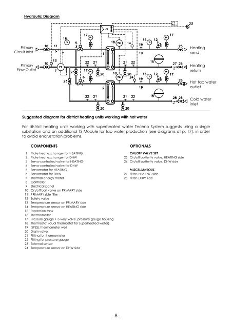
Hydraulic Diagram<br />
Primary<br />
Circuit Inlet<br />
Heating<br />
send<br />
Primary<br />
Flow Outlet<br />
Heating<br />
return<br />
Hot tap water<br />
outlet<br />
Cold water<br />
inlet<br />
Suggested diagram for district heating units working with hot water<br />
For district heating units working with superheated water <strong>Techno</strong> <strong>System</strong> suggests using a single<br />
substation and an additional TS Module for tap water production (see diagrams at p. 17), in order<br />
to avoid encrustation problems.<br />
COMPONENTS<br />
OPTIONALS<br />
1 Plate heat exchanger for HEATING ON/OFF VALVE SET<br />
2 Plate heat exchanger for DHW 25 On/off butterfly valve, HEATING side<br />
3 Servo-controlled valve for HEATING 26 On/off butterfly valve, DHW side<br />
4 Servo-controlled valve for DHW<br />
5 Servomotor for HEATING MISCELLANEOUS<br />
6 Servomotor for DHW 27 Filter, HEATING side<br />
7 Thermal energy meter 28 Filter, DHW side<br />
8 Controller<br />
9 Electrical panel<br />
10 On/off ball valve on PRIMARY side<br />
11 PRIMARY side filter<br />
12 Safety valve<br />
13 Temperature sensor on PRIMARY side<br />
14 Temperature sensor on HEATING side<br />
15 Expansion tank<br />
16 Thermometer<br />
17 Pressure gauge + 3-way valve, pressure gauge housing<br />
18 Thermostat (dual thermostat for superheated water)<br />
19 ISPESL thermometer well<br />
20 Drain valve<br />
21 Fitting for thermometer<br />
22 Fitting for pressure gauge<br />
23 External sensor<br />
24 Temperature sensor on DHW side<br />
- 8 -