SOTTOSTAZIONI PER TELERISCALDAMENTO - Techno System
SOTTOSTAZIONI PER TELERISCALDAMENTO - Techno System
SOTTOSTAZIONI PER TELERISCALDAMENTO - Techno System

Create successful ePaper yourself
Turn your PDF publications into a flip-book with our unique Google optimized e-Paper software.
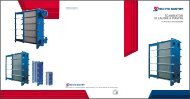
<strong>SOTTOSTAZIONI</strong><br />
<strong>PER</strong> <strong>TELERISCALDAMENTO</strong><br />
DISTRICT HEATING SUBSTATIONS
INDEX<br />
Ed. 20130114<br />
GENERAL INFORMATION ................................................................................................................................. 2<br />
Before installing ......................................................................................................................................... 2<br />
Materials and PED (97/23/CE) Standards ............................................................................................. 3<br />
SKID-TYPE DISTRICT HEATING SUBSTATIONS ................................................................................................... 4<br />
Technical Features ................................................................................................................................... 4<br />
SKID-TYPE SUBSTATION FOR HEATING USE ONLY .................................................................................... 5<br />
Hydraulic Diagram ................................................................................................................................... 6<br />
SKID-TYPE SUBSTATION FOR HEATING AND DOMESTIC HOT-WATER PRODUCTION (with heat<br />
exchangers in parallel configuration) ................................................................................................... 7<br />
Hydraulic Diagram ................................................................................................................................... 8<br />
WALL-MOUNTED DISTRICT HEATING SUBSTATIONS ....................................................................................... 9<br />
Technical Features ................................................................................................................................... 9<br />
WALL-MOUNTED SUBSTATION FOR HEATING USE ONLY ...................................................................... 10<br />
Capacities and Dimensions.................................................................................................................. 10<br />
Hydraulic Diagram ................................................................................................................................. 11<br />
WALL-MOUNTED SUBSTATION FOR HEATING AND DOMESTIC HOT-WATER PRODUCTION (with heat<br />
exchangers in parallel configuration) ................................................................................................. 12<br />
Capacities and Dimensions.................................................................................................................. 12<br />
Hydraulic Diagram ................................................................................................................................. 13<br />
WALL-MOUNTED SUBSTATION FOR HEATING AND DOMESTIC HOT WATER PRODUCTION (with heat<br />
exchangers in series configuration) ..................................................................................................... 14<br />
Capacities and Dimensions.................................................................................................................. 14<br />
Hydraulic Diagram ................................................................................................................................. 15<br />
EXAMPLES OF SYSTEM LAYOUTS .................................................................................................................... 16<br />
LEGEND .................................................................................................................................................... 16<br />
DIAGRAM No. 1 ...................................................................................................................................... 17<br />
DIAGRAM No. 2 ...................................................................................................................................... 17<br />
DIAGRAM No. 3 ...................................................................................................................................... 17<br />
DIAGRAM No. 4 ...................................................................................................................................... 18<br />
DIAGRAM No. 5 ...................................................................................................................................... 18<br />
DIAGRAM No. 6 ...................................................................................................................................... 18<br />
DIAGRAM No. 7 ...................................................................................................................................... 19<br />
This document was created by the TECHNO SYSTEM Technical Office.<br />
All rights reserved.<br />
This document may not be reproduced in whole or in part without explicit written authorization by<br />
<strong>Techno</strong> <strong>System</strong>.<br />
<strong>Techno</strong> <strong>System</strong> also reserves the right to modify the technical features and construction data of<br />
any product referred to herein at any time and without notice.
- 1 -
GENERAL INFORMATION<br />
TECHNO SYSTEM, a long-time leader in the district heating sector, builds skid-type substations (for medium<br />
and high capacity applications) complete with all the components needed for ensuring safety and for<br />
heat measurement and regulation as well as fittings for remote management. The substations are<br />
compact, can be completely dismantled, and can be installed even in small or difficult-to-access<br />
spaces.<br />
The TECHNO SYSTEM district heating substations are supplied as pre-assembled, pre-cabled units that<br />
interface with the vector fluid delivery system (superheated or hot water) distributed by the energy<br />
production and/or supply companies to permit the user system – which operates at a lower temperature<br />
and pressure – to draw off the quantity of energy (heat) needed for heating and/or production of<br />
domestic hot water.<br />
The district heating substation is a thermal exchange system comprising plate heat exchangers supplied<br />
by superheated or hot water for heating via radiators, fan coils, floor panels, etc., and/or for production<br />
of domestic hot water (DHW).<br />
The heat exchangers are the TECHNO SYSTEM plate type, correctly dimensioned in accordance with project<br />
data and technical specifications. The electrical panel supplied with the substation is the standard TECHNO<br />
SYSTEM panel for DHS substations, featuring small size and full conformity with pertinent laws, standards, and<br />
regulations.<br />
The TECHNO SYSTEM substations are pre-assembled and tested at our plant and can be supplied<br />
complete with insulation on the piping and heat exchangers.<br />
The overall dimensions of the substations reflect the principles of maximum compactness typical of all<br />
TECHNO SYSTEM DHS substations. Any special adaptations to the substations are subject to separate<br />
estimate.<br />
For building its DHS substations, TECHNO SYSTEMS uses only materials conforming to the requirements of<br />
the Pressure Equipment Directive (“PED Directive”) - 97/23/EC - and in compliance with the provisions<br />
of the Italian “Raccolta R” Edition 2009. The procedures and welding equipment used are DNV-qualified<br />
in accordance with EN 15614 and EN 287 PED.<br />
Where applicable, x-ray inspection of the piping welds is conducted in accordance with TECHNO<br />
SYSTEM standard procedures: 10% of the welded joins on category PED I, II, III, and IV substations are<br />
inspected, while no x-ray inspections are called for in the case of substations covered by Art. 3 § 3,<br />
which are also welded in accordance with EN 15614 and EN 287 PED standards.<br />
The construction materials and production and testing methods used for building, testing, and outfitting<br />
the TECHNO SYSTEM substations (carrying ISO 9001-2008 and PED certification issued by DNV) all meet<br />
the standards set by the PED Directive. Each substation is supplied complete with statement of PED<br />
compliance.<br />
In the wall-mounted DHS substations, the heat exchangers (in series or in parallel) are inserted in a loadbearing<br />
structure in hot-galvanized sheet with jacket (for the wall-hung version) or with epoxy- finished<br />
sheet-metal cornice (for the recessed version).<br />
In the version featuring parallel exchangers, heating may operate simultaneously with DHW production,<br />
while DHW takes priority over heating in the version with series-mounted exchangers.<br />
In the skid-type DHS substations, the heat exchangers are installed on a load-bearing carbon-steel base<br />
with singly-adjustable feet.<br />
All the TECHNO SYSTEM district heating substations are equipped with an electrical control panel<br />
featuring a customizable PID (Proportional Integral Derivative) programmable logic digital controller with<br />
the most widely-used combinations pre-programmed.<br />
Before installing<br />
Since there do not exist any technical standards making explicit reference to particular sites in which to<br />
install the substation for safety reasons, it is the responsibility of the system designer and/or installer to<br />
select the most suitable location for installation.<br />
It is nevertheless prudent to not install the substation in direct contact with walls and/or other equipment<br />
installed in the “boiler room” in order to guarantee the best possible access in view of future routine and<br />
extraordinary maintenance operations.<br />
Insofar as concerns the electrical supply system, refer to Italian Law no. 46/90 of March 1990 and to the<br />
pertinent CEI (IEC) standards.<br />
Also remember that this type of heat generator is subject to the provisions of Italian Presidential Decree<br />
no. 412/93 concerning energy consumption for thermal uses in buildings.<br />
- 2 -
All the pre-assembled substations built by TECHNO SYSTEM comply with the Pressure Equipment (PED)<br />
97/23/EC, Low Voltage 73/23/EC, and Electromagnetic Compatibility 89/336/EC Directives, are supplied<br />
complete with all relevant documentation (Statement of PED Compliance, CE mark, use and<br />
maintenance manuals) called for by applicable laws, regulations, and standards, and are fully<br />
compliant with the prescriptions of said documents. All the pre-assembled substations built by TECHNO<br />
SYSTEM are constructed in conformity with the provisions of the Italian “Raccolta R” Edition 2009.<br />
Materials and PED (97/23/CE) Standards<br />
Following the entry into force of the Pressure Equipment Directive (PED - 97/23/EC), TECHNO SYSTEM<br />
accelerated its ongoing quest for quality al all levels, to ensure full compliance with the Directive of all<br />
the models of TECHNO SYSTEM heat exchangers.<br />
For the company, this step entailed obtaining certification of its Quality <strong>System</strong> certification and, at the<br />
same time, Form H and H1 PED certification.<br />
The ensuing comprehensive revision of heat exchanger design and construction entailed redefinition<br />
and consequent improvement of all the safety and quality parameters, through use of materials with<br />
excellent mechanical properties.<br />
- 3 -
SKID-TYPE DISTRICT HEATING SUBSTATIONS<br />
Primary Circuit<br />
Inlet<br />
Secondary<br />
Circuit Flow<br />
Outlet<br />
Primary<br />
Circuit Flow<br />
Outlet<br />
Secondary<br />
Return Inlet<br />
Technical Features<br />
Maximum operating pressure DHS network 16 bar (optional PN25)<br />
Maximum operating pressure Heating side according to demand (max 8 bar)<br />
Maximum operating pressure DHW side 6 bar (where applicable)<br />
Maximum differential pressure on primary side 16 bar<br />
Minimum differential pressure on primary side close to substation 2 bar<br />
Maximum pressure drop on primary side 1bar<br />
Test pressure (differential) 1.43 times design pressure.<br />
Protection Class IP54<br />
Electrical supply voltage 230 V (optional 380 V)<br />
Electrical supply frequency 50 Hz<br />
The district heating substation is a fully pre-assembled, pre-cabled unit for heat transmission, featuring<br />
high yield and maximum operating safety. The base is built of steel sections which house:<br />
o Inspectable plate heat exchangers (corrugated or smooth plates) or braze welded heat exchangers<br />
o Safety accessories:<br />
• Safety valves, ISPESL certified (PED)<br />
• Expansion tank<br />
o Monitoring accessories:<br />
• Pressure gauges<br />
• Thermometers<br />
• Immersion sensors<br />
o Protection accessories:<br />
• Safety thermostats<br />
• Temperature-control thermostat (for hot water) or regulation and safety dual thermostat (for<br />
superheated water)<br />
o Control accessories:<br />
• Two-way seated poppet valves<br />
• Electrical servo control for the above-mentioned valves<br />
o Automatic control accessories:<br />
• Thermal regulation station for monitoring temperatures at various points and programming and<br />
defining parameters for the physical and electrical values to be managed.<br />
o<br />
Main electrical control panel<br />
On request, the skid-type district heating substations may be supplied fully insulated (exchanger and<br />
piping) or partially insulated (exchanger only or piping only).<br />
N.B. Substations of this type may also be constructed for domestic hot water production alone. Such a<br />
version does not include the electrical panel, thermal regulation unit, or the external sensor. The off-site<br />
elements (as shown in the diagram below) must be connected to the thermal regulation panel of<br />
another substation designed for heating use only.<br />
- 4 -
SKID-TYPE SUBSTATION FOR HEATING USE ONLY<br />
This type of substation is suitable for high and medium capacity systems supplied by superheated water<br />
or hot water. It is designed for heating use only and can be equipped with the SIEMENS RVD (or similar)<br />
controller or with the TECHNO SYSTEM TSRE 010 temperature-control system.<br />
These substations integrate perfectly with systems for instantaneous production of domestic hot water<br />
with accumulation tanks, boilers, solar panels, and for pool heating systems, for example through<br />
application of specific modules units produced by TECHNO SYSTEM (refer to the examples included as<br />
attachments in this folder).<br />
With this type of substation, users can:<br />
• directly set the heating set-point using easy-access dedicated pushbuttons. (TSRE 010)<br />
• manage heating independently, with separate onboard timers and weekly programs (TSRE 010)<br />
• manage heating by external thermostat/timer-thermostat or on the basis of a weekly schedule<br />
programmed in the controller (on/off settings at half-hour intervals) (TSRE 010)<br />
• set SUMMER or WINTER parameters (heating deactivated in SUMMER mode)<br />
• manage heating temperature by the fixed-point or climate-curve method<br />
• lock the heating-side set-point for systems serving floor panels (TSRE 010)<br />
• set an ANTI-SCUFF cycle for the HEATING side pump (if installed) when system is in SUMMER mode<br />
• set an ANTIFREEZE cycle with minimum threshold<br />
• maintain temperature in the primary circuit via hydraulic bypass (with ball valve) or managed by the<br />
regulator (with times, intervals, and quantities set via the onboard calendar) (TSRE 010)<br />
• connect a safety thermostat on the heating side (for floor-panel systems) featuring cut-in signal (by<br />
acoustic alarm and display message)<br />
• signal sensor malfunction (by acoustic alarm and display message) (TSRE 010)<br />
• signal excessive pressure in the heating circuit by acoustic alarm and display message and signal<br />
low water level in the heating circuit (and shutdown of the heating side pump, if applicable) by<br />
acoustic alarm and display message (TSRE 010)<br />
• reset the values to factory defaults.<br />
Additionally, this type of substation is prepared for installing devices for:<br />
• limiting the flow rate on the DHS side<br />
• limiting the return temperature on the DHS side, with sensor malfunction signal (by acoustic alarm<br />
and display message)<br />
• remote reading of the thermal energy meter<br />
• remote control<br />
• managing a GSM or PSTN modem connection, which permits sending SMSs or e-mails for notifying<br />
alarms or malfunctions (TSRE 010).<br />
Heating<br />
Capacity<br />
(kW)<br />
Design<br />
Temperature<br />
(°C)<br />
Overall dimensions (mm)<br />
Length x Height x Width<br />
Connections<br />
on Primary Side<br />
Connections on<br />
Secondary Side<br />
Empty<br />
Weight<br />
(kg)<br />
200 100 1390x1830x500 DN40 DN50 250<br />
400 100 1560x1870x560 DN50 DN65 400<br />
600 100 1770x1870x610 DN65 DN80 450<br />
800 100 1730x1870x615 DN80 DN100 500<br />
1000 100 1935x1890x1000 DN80 DN100 800<br />
200 140 1160x1680x500 DN25 DN50 200<br />
400 140 1405x1870x550 DN40 DN65 350<br />
600 140 1520x1870x600 DN50 DN80 400<br />
800 140 1780x1870x600 DN50 DN100 450<br />
1000 140 1915x1840x1000 DN65 DN100 750<br />
NOTE: each substation is dimensioned on the basis of the pressure on the two circuits, the thermal head,<br />
and/or the heating capacity requested by the customer. For this reason, the overall dimensions of the<br />
substations are subject to change, case by case; the maximum measurements are suggested by the above<br />
table (calculation of table values is based on TECHNO SYSTEM standard parameters). Wall-mounted<br />
substations are available for heating capacities equal to or less than 150 kW.<br />
- 5 -
Hydraulic Diagram<br />
Primary<br />
Circuit Inlet<br />
Primary<br />
Flow Outlet<br />
Secondary<br />
Delivery<br />
Secondario<br />
Secondary<br />
Return<br />
COMPONENTS<br />
OPTIONALS<br />
1 Plate heat exchanger for HEATING ON/OFF VALVE SET<br />
3 Servo-controlled valve for HEATING 25 On/off butterfly valve, HEATING side<br />
5 Servomotor for HEATING MISCELLANEOUS<br />
7 Thermal energy meter 27 Filter, HEATING side<br />
8 Controller<br />
9 Electrical panel<br />
10 On/off ball valve on PRIMARY side<br />
11 PRIMARY side filter<br />
12 Safety valve<br />
13 Temperature sensor on PRIMARY side<br />
14 Temperature sensor on HEATING side<br />
15 Expansion tank<br />
16 Thermometer<br />
17 Pressure gauge + 3-way valve, pressure gauge housing<br />
18 Thermostat (dual thermostat for superheated water)<br />
19 ISPESL thermometer well<br />
20 Drain valve<br />
21 Fitting for thermometer<br />
22 Fitting for pressure gauge<br />
23 External sensor<br />
- 6 -
SKID-TYPE SUBSTATION FOR HEATING AND DOMESTIC HOT-WATER PRODUCTION<br />
(with heat exchangers in parallel configuration)<br />
This type of substation is suitable for high and medium capacity systems, supplied by superheated water<br />
or hot water, for heating and production of domestic hot water.<br />
This type of substation is recommended for systems requiring separate and independent management<br />
of the heating and domestic hot water circuits.<br />
These skid-type substations can be equipped with the SIEMENS RVD (or similar) controller or with the<br />
TECHNO SYSTEM TSRE 010 temperature-control system.<br />
With this type of substation, users can:<br />
• directly set the heating set-point and the DHW set-point using easy-access dedicated pushbuttons.<br />
(TSRE 010)<br />
• manage heating and DHW production independently, with separate onboard timers and weekly<br />
programs.<br />
• manage heating by external thermostat/timer-thermostat or on the basis of a weekly schedule<br />
programmed in the controller (on/off settings at half-hour intervals). (TSRE 010)<br />
• set SUMMER or WINTER parameters (DHW only activated in SUMMER mode, DHW and heating<br />
activated in WINTER mode).<br />
• manage heating temperature by the fixed-point or climate-curve method.<br />
• set the set-points for heating, DHW, and recirculation (if applicable) independently.<br />
• with the special Economy function, give precedence to DHW over HEATING. (TSRE 010)<br />
• lock the heating-side set-point for systems serving floor panels. (TSRE 010)<br />
• set an ANTI-SCUFF cycle for the HEATING side pump (if installed) when system is in SUMMER mode.<br />
• set an ANTIFREEZE cycle with minimum threshold.<br />
• maintain temperature in the primary circuit via hydraulic bypass (with ball valve) or managed by the<br />
regulator (with times, intervals, and quantities set via the onboard calendar). (TSRE 010)<br />
• connect a safety thermostat on the heating side (for floor-panel systems) featuring cut-in signal (by<br />
acoustic alarm and display message.<br />
• connect a safety thermostat on the DHW side (for protection against scalding) featuring cut-in signal<br />
(by acoustic alarm and display message).<br />
• signal sensor malfunction (by acoustic alarm and display message. (TSRE 010)<br />
• signal excessive pressure in the heating circuit by acoustic alarm and display message and signal<br />
low water level in the heating circuit (and shutdown of the heating side pump, if applicable) by<br />
acoustic alarm and display message). (TSRE 010)<br />
• reset the values to factory defaults.<br />
• integrate into other systems with accumulators, traditional boilers, and solar panels.<br />
Additionally, this type of substation is prepared for installing devices for:<br />
• managing recirculation via PID with set-point independent of DHW.<br />
• managing an ANTI-LEGIONELLA thermal disinfection cycle via onboard calendar (the system must<br />
comprise recirculation).<br />
• limiting the flow rate on the DHS side.<br />
• limiting the return temperature on the DHS side, with sensor malfunction signal (by acoustic alarm<br />
and display message).<br />
• remote reading of the thermal energy meter.<br />
• remote control.<br />
• managing a GSM or PSTN modem connection, which permits sending SMSs or e-mails for notifying<br />
alarms or malfunctions.<br />
Note: each substation is dimensioned on the basis of the pressure on the two circuits, the thermal head,<br />
and/or the heating capacity requested by the customer. For this reason, the overall dimensions of the<br />
substations are subject to change, case by case.<br />
- 7 -
Hydraulic Diagram<br />
Primary<br />
Circuit Inlet<br />
Heating<br />
send<br />
Primary<br />
Flow Outlet<br />
Heating<br />
return<br />
Hot tap water<br />
outlet<br />
Cold water<br />
inlet<br />
Suggested diagram for district heating units working with hot water<br />
For district heating units working with superheated water <strong>Techno</strong> <strong>System</strong> suggests using a single<br />
substation and an additional TS Module for tap water production (see diagrams at p. 17), in order<br />
to avoid encrustation problems.<br />
COMPONENTS<br />
OPTIONALS<br />
1 Plate heat exchanger for HEATING ON/OFF VALVE SET<br />
2 Plate heat exchanger for DHW 25 On/off butterfly valve, HEATING side<br />
3 Servo-controlled valve for HEATING 26 On/off butterfly valve, DHW side<br />
4 Servo-controlled valve for DHW<br />
5 Servomotor for HEATING MISCELLANEOUS<br />
6 Servomotor for DHW 27 Filter, HEATING side<br />
7 Thermal energy meter 28 Filter, DHW side<br />
8 Controller<br />
9 Electrical panel<br />
10 On/off ball valve on PRIMARY side<br />
11 PRIMARY side filter<br />
12 Safety valve<br />
13 Temperature sensor on PRIMARY side<br />
14 Temperature sensor on HEATING side<br />
15 Expansion tank<br />
16 Thermometer<br />
17 Pressure gauge + 3-way valve, pressure gauge housing<br />
18 Thermostat (dual thermostat for superheated water)<br />
19 ISPESL thermometer well<br />
20 Drain valve<br />
21 Fitting for thermometer<br />
22 Fitting for pressure gauge<br />
23 External sensor<br />
24 Temperature sensor on DHW side<br />
- 8 -
WALL-MOUNTED DISTRICT HEATING SUBSTATIONS<br />
Technical Features<br />
Maximum operating pressure DHS network 16 bar (optional PN25)<br />
Maximum operating pressure Heating side 2.7 bar<br />
Maximum operating pressure DHW side 6 bar (where applicable)<br />
Maximum differential pressure on primary side 12 bar (for some models optional 3.5 bar)<br />
Minimum differential pressure on primary side close to substation 2 bar<br />
Maximum pressure drop on primary side 1bar<br />
Test pressure (differential) 1.43 times design pressure.<br />
Minimum guaranteed residual head on Heating side 2.5 m.c.a.<br />
Protection Class IP54<br />
Electrical supply voltage 230 V<br />
Electrical supply frequency 50 Hz<br />
The district heating substation is a fully pre-assembled, pre-cabled unit for heat transmission, featuring<br />
high yield and maximum operating safety. The structure consists of a zinc-plated frame covered with<br />
protective jackets in painted sheet metal which define the overall dimensions of the substation and<br />
houses:<br />
o<br />
o<br />
o<br />
o<br />
o<br />
o<br />
Braze welded plate heat exchangers<br />
Safety accessories:<br />
• Safety valves, ISPESL certified (PED)<br />
• Expansion tank<br />
Monitoring accessories:<br />
• Pressure gauges<br />
• Thermometers<br />
• High-sensitivity immersion sensors<br />
Protection accessories:<br />
• Safety thermostats<br />
• Safety dual thermostat for superheated water and single thermometer for hot water<br />
Control accessories:<br />
• Two-way seated poppet valves<br />
• Electrical servo control for the above-mentioned valves<br />
Automatic control accessories:<br />
• Thermal regulation station for monitoring temperatures at various points and programming and<br />
defining parameters for the physical and electrical values to be managed.<br />
o Main electrical control panel<br />
The wall-mounted district heating substations are available in two installation versions:<br />
• wall-hung<br />
• recessed<br />
The wall-mounted district heating substations are available:<br />
• for heating only<br />
• for heating and DHW production<br />
On request, the wall-mounted district heating substations can be supplied fully insulated, with a<br />
shell installed inside the frame.<br />
- 9 -
WALL-MOUNTED SUBSTATION FOR HEATING USE ONLY<br />
This type of substation is suitable for small capacity systems supplied by hot water or superheated<br />
water. It is designed for heating use only (radiators, fan coils, floor panels, etc.) when production of<br />
domestic hot water is not required.<br />
This type of substation is equipped with the TECHNO SYSTEM TSRE 010 temperature-control system.<br />
With this type of substation, users can:<br />
• directly set the heating set-point using easy-access dedicated pushbuttons.<br />
• read the heating delivery temperatures directly on the controller display.<br />
• manage heating independently, with separate onboard timers and weekly programs.<br />
• manage heating by external thermostat/timer-thermostat or on the basis of a weekly schedule<br />
programmed in the controller (on/off settings at half-hour intervals).<br />
• set SUMMER or WINTER parameters (heating deactivated in SUMMER mode).<br />
• manage heating temperature by the fixed-point or climate-curve method.<br />
• lock the heating-side set-point for systems serving floor panels.<br />
• set an ANTI-SCUFF cycle for the HEATING side pump (if installed) when system is in SUMMER mode.<br />
• set an ANTIFREEZE cycle with minimum threshold.<br />
• maintain temperature in the primary circuit managed by the regulator (with times, intervals, and<br />
quantities set via the onboard calendar) or on request with by-pass through the ball valve.<br />
• connect a safety thermostat on the heating side (for floor-panel systems) featuring cut-in signal (by<br />
acoustic alarm and display message).<br />
• signal sensor malfunction (by acoustic alarm and display message). (TSRE 010)<br />
• signal excessive pressure in the heating circuit by acoustic alarm and display message and signal<br />
low water level in the heating circuit (and shutdown of the heating side pump, if applicable) by<br />
acoustic alarm and display message.<br />
• reset the values to factory defaults.<br />
• integrate into other systems with accumulators, traditional boilers, and solar panels.<br />
Additionally, this type of substation is prepared for installing devices for:<br />
• limiting the flow rate on the DHS side.<br />
• limiting the return temperature on the DHS side, with sensor malfunction signal (by acoustic alarm<br />
and display message).<br />
• remote reading of the thermal energy meter.<br />
• remote control.<br />
• managing a GSM or PSTN modem connection, which permits sending SMSs or e-mails for notifying<br />
alarms or malfunctions.<br />
Capacities and Dimensions<br />
Model<br />
Heating<br />
Capacity<br />
(kW)<br />
Overall dimensions (mm)<br />
Length x Height x Width<br />
Connections on<br />
Primary Side<br />
Connections on<br />
Heating Side<br />
Empty Weight<br />
(kg)<br />
R34T 34 580x585x220 G 1” G 3/4” 20<br />
R50T 50 580x585x220 G 1” G 1” 28<br />
R75T 75 760x765x275 G 11/4” G 11/4” 60<br />
R100T 100 760x765x275 G 11/4” G 11/4” 61<br />
R116T 116 760x765x275 G 11/4” G 11/4” 62<br />
NOTE: the dimensions reported are purely indicative and refer to wall-hung substations constructed in<br />
accordance with TECHNO SYSTEM standards (dimensions may differ in the case of the recessed version).<br />
- 10 -
Hydraulic Diagram<br />
Primary<br />
Circuit Inlet<br />
Primary<br />
Flow Outlet<br />
COMPONENTS<br />
OPTIONALS<br />
1 Plate heat exchanger for HEATING ON/OFF VALVE SET<br />
3 Servo-controlled valve for HEATING 21 On/off ball valve on PRIMARY side<br />
5 Servomotor for HEATING 22 On/off ball valve on HEATING side<br />
7 Thermal energy meter TEM<strong>PER</strong>ATURE LIMITER SET PRIMARY SIDE<br />
8 Controller 24 Limit temperature sensor for PRIMARY side<br />
9 Electrical panel DELIVERY LIMITER SET PRIMARY SIDE<br />
11 Filter 25 Thermal energy meter with pulse counter card<br />
12 Safety valve TEM<strong>PER</strong>ATURE SAFETY SET HEATING SIDE FOR FLOOR<br />
13 Temperature sensor on HEATING side PANEL SYSTEM<br />
15 Expansion tank 26 Thermostat on HEATING side<br />
16 Vent ball valve on PRIMARY side SU<strong>PER</strong>HEATED WATER<br />
18 Vent valve on HEATING side 27 Dual thermostat<br />
28 ISPESL thermometer well<br />
PRESSURE SAFETY SET HEATING SIDE<br />
31 Maximum/Minimum pressure switch<br />
PUMP SET<br />
32 Minimum pressure switch<br />
33 Circulation pump<br />
MISCELLANEOUS<br />
34 External sensor<br />
35 Bypass ball valve<br />
- 11 -
WALL-MOUNTED SUBSTATION FOR HEATING AND DOMESTIC HOT-WATER<br />
PRODUCTION (with heat exchangers in parallel configuration)<br />
This type of substation is suitable for small capacity systems, supplied by hot water (or superheated)<br />
for heating (via radiators, fan coils, floor panels, etc.) and production of domestic hot water.<br />
This type of substation is recommended for systems requiring separate and independent<br />
management of the heating and domestic hot water circuits (the system may also be configured<br />
to give precedence to production of hot water over heating).<br />
This type of substation is equipped with the TECHNO SYSTEM TSRE 010 temperature-control system.<br />
With this type of substation, users can:<br />
• directly set the heating set-point and the DHW set-point using easy-access dedicated pushbuttons.<br />
• read the heating delivery, DHW, and recirculation (if applicable) temperatures directly on the<br />
controller display.<br />
• manage heating and DHW production independently, with separate onboard timers and weekly<br />
programs.<br />
• manage heating by external thermostat/timer-thermostat or on the basis of a weekly schedule<br />
programmed in the controller (on/off settings at half-hour intervals.<br />
• set SUMMER or WINTER parameters (DHW only activated in SUMMER mode, DHW and heating<br />
activated in WINTER mode).<br />
• manage heating temperature by the fixed-point or climate-curve method.<br />
• set the set-points for heating, DHW, and recirculation (if applicable) independently.<br />
• with the special Economy function, give precedence to DHW over HEATING.<br />
• lock the heating-side set-point for systems serving floor panels.<br />
• set an ANTI-SCUFF cycle for the HEATING side pump (if installed) when system is in SUMMER mode.<br />
• set an ANTIFREEZE cycle with minimum threshold.<br />
• maintain temperature in the primary circuit via bypass (with ball valve) or managed by the regulator<br />
(with times, intervals, and quantities set via the onboard calendar).<br />
• connect a safety thermostat on the heating side (for floor-panel systems) featuring cut-in signal (by<br />
acoustic alarm and display message).<br />
• connect a safety thermostat on the DHW side (for protection against scalding) featuring cut-in signal<br />
(by acoustic alarm and display message).<br />
• signal sensor malfunction (by acoustic alarm and display message.<br />
• signal excessive pressure in the heating circuit by acoustic alarm and display message and signal<br />
low water level in the heating circuit (and shutdown of the heating side pump, if applicable) by<br />
acoustic alarm and display message).<br />
• reset the values to factory defaults.<br />
• integrate into other systems with accumulators, traditional boilers, and solar panels.<br />
Additionally, this type of substation is prepared for installing devices for:<br />
• managing recirculation via PID with set-point independent of DHW.<br />
• managing an ANTI-LEGIONELLA thermal disinfection cycle via onboard calendar (the system must<br />
comprise recirculation).<br />
• limiting the flow rate on the DHS side.<br />
• limiting the return temperature on the DHS side, with sensor malfunction signal (by acoustic alarm<br />
and display message).<br />
• remote reading of the thermal energy meter.<br />
• remote control.<br />
• managing a GSM or PSTN modem connection, which permits sending SMSs or e-mails for notifying<br />
alarms or malfunctions.<br />
Capacities and Dimensions<br />
Model<br />
Heating<br />
Capacity<br />
(kW)<br />
Overall dimensions (mm)<br />
Length x Height x Width<br />
Connections on<br />
Primary Side<br />
Connections on<br />
Heating Side<br />
Connections<br />
on DHW Side<br />
Empty Weight<br />
(kg)<br />
RI34T.P 34+34 580x585x220 G 1” G 3/4” G 1/2” 30<br />
RI50T.P 50+34 760x765x275 G 11/4” G 1” G 1/2” 45<br />
NOTE: the dimensions reported are purely indicative and refer to wall-hung substations constructed in<br />
accordance with TECHNO SYSTEM standards (dimensions may differ in the case of the recessed version).<br />
- 12 -
Hydraulic Diagram<br />
Primary<br />
Circuit Inlet<br />
Primary<br />
Flow Outlet<br />
Recirculation<br />
Cold<br />
Water Inlet<br />
COMPONENTS<br />
OPTIONALS<br />
1 Plate heat exchanger for HEATING ON/OFF VALVE SET<br />
2 Plate heat exchanger for DHW 21 On/off ball valve on PRIMARY side<br />
3 Servo-controlled valve for HEATING 22 On/off ball valve on HEATING side<br />
4 Servo-controlled valve for DHW 23 On/off ball valve on DHW side<br />
5 Servomotor for HEATING TEM<strong>PER</strong>ATURE LIMITER SET PRIMARY SIDE<br />
6 Servomotor for DHW 24 Limit temperature sensor for PRIMARY side<br />
7 Thermal energy meter DELIVERY LIMITER SET PRIMARY SIDE<br />
8 Controller 25 Thermal energy meter with pulse counter card<br />
9 Electrical panel TEM<strong>PER</strong>ATURE SAFETY SET HEATING SIDE FOR FLOOR<br />
10 Flow switch PANEL SYSTEM<br />
11 Filter 26 Thermostat on HEATING side<br />
12 Safety valve TEM<strong>PER</strong>ATURE SAFETY SET DHW SIDE (ANTI-SCALDING)<br />
13 Temperature sensor on HEATING side 27 Thermostat on DHW side<br />
14 Temperature sensor on DHW side RECIRCULATION SET<br />
15 Expansion tank 28 Temperature sensor on RECIRCULATION side<br />
16 Vent ball valve on PRIMARY side 29 Safety valve on DHW side<br />
17 Bypass ball valve 30 Vent valve on DHW side<br />
18 Vent valve on HEATING side 31 On/off ball valve on RECIRCULATION side<br />
19 Filling ball valve PRESSURE SAFETY SET HEATING SIDE<br />
20 Pressure gauge 32 Maximum/Minimum pressure switch<br />
PUMP SET<br />
33 Minimum pressure switch<br />
34 Circulation pump<br />
MISCELLANEOUS<br />
35 External sensor<br />
- 13 -
WALL-MOUNTED SUBSTATION FOR HEATING AND DOMESTIC HOT WATER<br />
PRODUCTION (with heat exchangers in series configuration)<br />
This type of substation is suitable for small capacity systems supplied by superheated water (or by<br />
hot water at sufficiently high temperature). It is designed for heating (via radiators, fan coils, floor<br />
panels, etc.) and production of domestic hot water.<br />
This type of substation is recommended for systems in which independent management of the<br />
heating and domestic hot water circuits is not required (hot water production always takes<br />
precedence over heating).<br />
This type of substation is equipped with the TECHNO SYSTEM TSRE 010 temperature-control system.<br />
With this type of substation, users can:<br />
• directly set the heating set-point using easy-access dedicated pushbuttons.<br />
• read the heating delivery, DHW, and recirculation (if applicable) temperatures directly on the<br />
controller display.<br />
• manage heating and DHW production independently, with separate onboard timers and weekly<br />
programs.<br />
• manage heating by external thermostat/timer-thermostat or on the basis of a weekly schedule<br />
programmed in the controller (on/off settings at half-hour intervals.<br />
• set SUMMER or WINTER parameters (DHW only activated in SUMMER mode, DHW and heating<br />
activated in WINTER mode).<br />
• manage heating temperature by the fixed-point or climate-curve method.<br />
• set the set-points for heating, DHW, and recirculation (if applicable) independently.<br />
• lock the heating-side set-point for systems serving floor panels.<br />
• set an ANTI-SCUFF cycle for the HEATING side pump (if installed) when system is in SUMMER mode.<br />
• set an ANTIFREEZE cycle with minimum threshold.<br />
• maintain temperature in the primary circuit managed by the regulator (with times, intervals, and<br />
quantities set via the onboard calendar) or on request with by-pass through the ball valve.<br />
• connect a safety thermostat on the heating side (for floor-panel systems) featuring cut-in signal (by<br />
acoustic alarm and display message).<br />
• connect a safety thermostat on the DHW side (for protection against scalding) featuring cut-in signal<br />
(by acoustic alarm and display message.<br />
• signal sensor malfunction (by acoustic alarm and display message.<br />
• signal excessive pressure in the heating circuit by acoustic alarm and display message and signal<br />
low water level in the heating circuit (and shutdown of the heating side pump, if applicable) by<br />
acoustic alarm and display message).<br />
• reset the values to factory defaults.<br />
• integrate into other systems with accumulators, traditional boilers, and solar panels.<br />
Additionally, this type of substation is prepared for installing devices for:<br />
• managing recirculation via PID with set-point independent of DHW.<br />
• managing an ANTI-LEGIONELLA thermal disinfection cycle via onboard calendar (the system must<br />
comprise recirculation).<br />
• limiting the flow rate on the DHS side.<br />
• limiting the return temperature on the DHS side, with sensor malfunction signal (by acoustic alarm<br />
and display message).<br />
• remote reading of the thermal energy meter.<br />
• managing remote control.<br />
• managing a GSM or PSTN modem connection, which permits sending SMSs or e-mails for notifying<br />
alarms or malfunctions.<br />
Capacities and Dimensions<br />
Model Heating<br />
Capacity<br />
Overall dimensions (mm)<br />
Length x Height x Width<br />
Connections on<br />
Primary Side<br />
Connections on<br />
Heating Side<br />
Connections<br />
on DHW Side<br />
Empty Weight<br />
(kg)<br />
(kW)<br />
RI34T.S 34 580x585x220 G 3/4” G 3/4” G 1/2” 32<br />
NOTE: the dimensions reported are purely indicative and refer to wall-hung substations constructed in<br />
accordance with TECHNO SYSTEM standards (dimensions may differ in the case of the recessed version).<br />
- 14 -
Hydraulic Diagram<br />
Primary<br />
Circuit Inlet<br />
Primary<br />
Flow Outlet<br />
Recirculation<br />
Cold<br />
Water Inlet<br />
COMPONENTS<br />
OPTIONALS<br />
1 Interface plate heat exchanger ON/OFF VALVE SET<br />
2 Plate heat exchanger for DHW 21 On/off ball valve on PRIMARY side<br />
3 Servo-controlled valve 22 On/off ball valve on HEATING side<br />
4 Servomotor 23 On/off ball valve on DHW side<br />
5 3-way valve TEM<strong>PER</strong>ATURE LIMITER SET, PRIMARY SIDE<br />
6 Circulation pump 24 Limit temperature sensor for PRIMARY side<br />
7 Thermal energy meter DELIVERY LIMITER SET, PRIMARY SIDE<br />
8 Controller 25 Thermal energy meter with pulse counter card<br />
9 Electrical panel TEM<strong>PER</strong>ATURE SAFETY SET HEATING SIDE FOR FLOOR<br />
10 Flow switch PANEL SYSTEM<br />
11 Filter 26 Thermostat on HEATING side<br />
12 Safety valve TEM<strong>PER</strong>ATURE SAFETY SET DHW SIDE (ANTI-SCALDING)<br />
13 Temperature sensor on HEATING side 27 Thermostat on DHW side<br />
14 Temperature sensor on DHW side RECIRCULATION SET<br />
15 Expansion tank 28 Temperature sensor on RECIRCULATION side<br />
16 Vent ball valve on PRIMARY side 29 Safety valve on DHW side<br />
30 On/off valve on DHW side<br />
17 Dual thermostat PRESSURE SAFETY SET HEATING SIDE<br />
18 Vent valve on HEATING side 32 Maximum/Minimum pressure switch<br />
19 Filling ball valve MISCELLANEOUS<br />
20 Pressure gauge 33 Bypass ball valve<br />
31 Minimum pressure switch 34 External sensor<br />
- 15 -
EXAMPLES OF SYSTEM LAYOUTS<br />
LEGEND<br />
The symbols shown and explained in this section refer to the system layout diagrams reproduced below.<br />
Although these diagrams have been modified according to the needs of the designer, they are all<br />
highly reliable and thoroughly “field-tested.”<br />
Heat exchanger<br />
Ball valve<br />
ISPESL thermometer<br />
well<br />
Radiator Butterfly valve Expansion tank<br />
Hot domestic water<br />
outlet<br />
Safety valve<br />
Electrical panel<br />
Accumulation tank<br />
Thermal energy<br />
meter<br />
Logic unit (not<br />
supplied)<br />
Boiler Flow switch Non-return valve<br />
Solar panel External sensor A Water-softening unit<br />
Pool Room thermostat Pressure reducer<br />
2-way valve<br />
Temperature-control<br />
thermostat<br />
Bypass valve<br />
3-way valve<br />
Maximum pressure<br />
switch<br />
Water treatment<br />
3-way mixing valve<br />
Minimum pressure<br />
switch<br />
Pool filter<br />
Circulation pump Thermometer Pump with pre-filter<br />
Y filter<br />
Pressure gauge<br />
Hydraulic separator<br />
Sensor<br />
Vent valve<br />
- 16 -
DIAGRAM No. 1<br />
Skid-type substation for heating use only with integrated TS module for instantaneous domestic hot water<br />
production<br />
Primary<br />
Circuit Inlet<br />
Primario<br />
Primary<br />
Flow Outlet<br />
Primario<br />
DHS Substation<br />
A<br />
Recirculation<br />
Cold<br />
Water Inlet<br />
TS MDI Module<br />
DIAGRAM No. 2<br />
Skid-type substation for heating use only with integrated TS Module for use with accumulation tank for<br />
domestic hot water production<br />
Primary<br />
Circuit Inlet<br />
Primary<br />
Flow Outlet<br />
DHS Substation<br />
TS MDA Module<br />
Cold Water<br />
Inlet<br />
DIAGRAM No. 3<br />
Skid-type substation for heating use only with integrated TS Module for pool heating<br />
A<br />
Primary<br />
Circuit Inlet<br />
Primary<br />
Flow Outlet<br />
DHS Substation<br />
TS MDP Module<br />
- 17 -
DIAGRAM No. 4<br />
Skid-type or wall-mounted substation for heating use only with integrated boiler for domestic hot water<br />
production<br />
Primary<br />
Circuit Inlet<br />
Primary<br />
Flow Outlet<br />
DHS Substation<br />
Cold<br />
Water Inlet<br />
A<br />
Warning: in case of system installation employing wall-mounted substation, the heating side pump should not be supplied<br />
(or is supplied, should not be connected to the controller on the substation but, instead, to a logic unit external to the<br />
substation).<br />
DIAGRAM No. 5<br />
Wall-mounted substation with heat exchangers in parallel configuration and integrated accumulation tank<br />
Primary<br />
Circuit Inlet<br />
Primary<br />
Flow Outlet<br />
DHS Substation<br />
Cold Water<br />
Inlet<br />
A<br />
DIAGRAM No. 6<br />
Wall-mounted substation with heat exchangers in parallel configuration and integrated accumulators and<br />
solar panels<br />
Primary<br />
Circuit Inlet<br />
Primary<br />
Flow Outlet<br />
DHS Substation<br />
- 18 -<br />
Cold Water<br />
Inlet<br />
A
DIAGRAM No. 7<br />
Wall-mounted substation with parallel exchangers and hydraulic separator on heating circuit<br />
Primary<br />
Circuit Inlet<br />
Primary<br />
Flow Outlet<br />
DHS Substation<br />
A<br />
Cold Water<br />
Inlet<br />
- 19 -