
You also want an ePaper? Increase the reach of your titles
YUMPU automatically turns print PDFs into web optimized ePapers that Google loves.
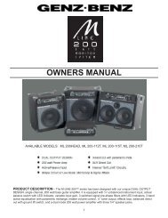
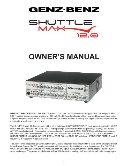
OWNER’S MANUAL<br />
PRODUCT DESCRIPTION – The SHUTTLE <strong>MAX</strong> <strong>12.0</strong> bass amplifier has been designed with our unique ULTRA<br />
LIGHT unified design process, yielding a 1200 watt (2 x 600 watt) professional high powered tour-class bass guitar<br />
amplifier weighing only 6.75 lbs! This compact design blends the best of analog and digital platforms to produce the<br />
ultimate in warmth, punch and power.<br />
The SHUTTLE <strong>MAX</strong> <strong>12.0</strong> is equipped with a ¼” unbalanced INSTRUMENT INPUT; input stage clip detector; MUTE<br />
switch with LED indicator; FET and 12AX7 TUBE preamps each with HIGH/LOW gain stage settings and 4 band<br />
ACTIVE equalization with 2 sweepable midrange bands; 3 switched SIGNAL SHAPE filters with level adjustments;<br />
MASTER VOLUME; proprietary OUTPUT LIMITER; TUNER OUT; AUX INPUT; 3 EFFECTS LOOPS; balanced<br />
DIRECT OUTPUT with GROUND LIFT, PRE or POST EQ; and MIC/LINE switches; HEADPHONE OUTPUT; and 2<br />
Neutrik NL-4 “Speakon” speaker jacks.<br />
The power amp design is a powerful, lightweight Class D design and is supported by a state-of-the-art digital Switch<br />
Mode Power Supply (SMPS), which does away with the weight of a traditional power transformer. The SHUTTLE<br />
<strong>MAX</strong> <strong>12.0</strong> uses two 600 watt amplifier modules, both driving full output power into 4 ohms speaker loads—1200<br />
watts total output. The power supply is usable from 100-240 volts, lending itself well to international touring players.
FRONT PANEL<br />
INPUT – The SHUTTLE <strong>MAX</strong> <strong>12.0</strong> is equipped with a standard ¼” unbalanced INPUT. The INPUT sensitivity range is<br />
from 40 mV to over 1.6 volts. The INPUT impedance is >500K ohms. The INPUT stage contains a precision high order<br />
active high pass filter (more effective and less intrusive than the more common 6 dB filters) and an “RFI” filter (radio<br />
frequency interference) to eliminate unwanted noise. The INPUT gain stages consist of a feedback type variable gain<br />
circuit that provides wide range, continuously variable gain with minimal noise. The preamp contains an FET input amp<br />
circuit based on our highly regarded GBE series touring amplifiers.<br />
INPUT SIGNAL MUTE SWITCH – With this MUTE switch, you can place the amplifier (and Direct Output) in standby<br />
mode between sets, without having to change any of your amp settings. This feature can also be used for silent tuning<br />
since the TUNER OUT stays active when the MUTE is engaged. A red LED indicates when the MUTE is active.<br />
This function is not operable from the included 5-button footswitch, but a rear panel jack is provided so a standard<br />
single button footswitch can be used to remotely engage this function. The switch on the amplifier’s faceplate must be<br />
in the out position for the footswitch to work properly.<br />
FET/TUBE CHANNEL SELECTOR SWITCH – This switch is provided to select either the FET channel or the TUBE<br />
channel. This function can be remotely engaged via the 5-button footswitch. The front panel switch must be in the out<br />
position for the foot switch to engage the function.<br />
CHANNEL MIX SELECTOR SWITCH – When engaged this switch combines the signal of the FET and TUBE channels<br />
together. This function can also be remotely engaged via the 5-button footswitch. The front panel switch must be<br />
in the out position for the footswitch to engage the function.<br />
FET CHANNEL---<br />
GAIN SWITCH (LOW/HIGH) – This switch sets the GAIN sensitivity for the FET channel. It works somewhat like an<br />
Active/Passive switch. The amber LED indicates that the HIGH setting is selected. The difference between the LOW<br />
and HIGH gain positions is approx. 10dB. Since there is a GAIN Switch provided for each channel this allows the<br />
player to set different gain structures for the FET or TUBE channels. If the cleanest possible signal is desired, we recommend<br />
that the LOW setting be used for basses with hotter output or active pickups (those with an output sensitivity<br />
over 1 Volt, generally most basses using one or two 9 volt batteries to power their on board preamp) and the HIGH<br />
gain setting be used for basses with lower output or passive pickups.<br />
PREAMP GAIN CONTROL – This control sets the GAIN level of the preamp to the output of your bass. If the red<br />
OVERLOAD “O/L” LED flashes when setting up your input levels, reduce the preamp gain control to eliminate any<br />
input preamp overload. You may want to check the setting of the GAIN switch as well.<br />
This GAIN control, in conjunction with the PREAMP VOLUME control allows you to set the signal level to the EQ section.<br />
The MASTER VOLUME then controls the total output level of the power amp.<br />
“O/L” LED – In the FET channel this LED senses the condition of the input signal after the GAIN control and also<br />
senses and warns of possible clipping in the EQ network. The “O/L” sensing circuit is very dependent upon the output<br />
of the bass instrument pickups, the GAIN and VOLUME level settings of the FET channel and the amount of EQ used<br />
i.e. the more radical the EQ boost and volume level of the PREAMP VOLUME control, the more possibility of an overload<br />
condition.<br />
If overloading of the FET channel is occurring adjusting the PREAMP GAIN and /or PREAMP VOLUME down will<br />
reduce or eliminate the over-load condition and adjusting the MASTER VOLUME up will return the overall loudness.<br />
Note: It is OK for this LED to flash occasionally with your hardest notes played and it may flash even if the TUBE<br />
channel has been selected for use. This is normal and is due to the mixing topology for the 2 channels.
PREAMP VOLUME CONTROL – This control sets the volume of the preamp after the INPUT and FET channel gain<br />
stages and before the EQ controls. Use this control in conjunction with the GAIN control and the MASTER VOLUME<br />
control for your overall output level.<br />
TUBE CHANNEL—<br />
GAIN SWITCH (LOW/HIGH) – This switch sets the GAIN sensitivity for the TUBE channel. It works both like an Active/Passive<br />
switch and like a GAIN boost switch. The amber LED indicates that the HIGH setting is selected. The<br />
difference between the LOW and HIGH gain positions is approx. 10dB. Since there is a GAIN switch provided for<br />
each channel this allows the player to set different gain structures for the FET or TUBE channels.<br />
If warm, clean tube tone is desired, we recommend that the LOW setting be used for basses with hotter output or<br />
active pickups (those with an output sensitivity over 1 Volt, generally most basses using one or two 9 volt batteries to<br />
power their on board preamp) and the HIGH gain setting be used for basses with lower output or passive pickups.<br />
If tube compression, growl, or all-out distortion is desired then the HIGH gain setting may be used regardless of the<br />
pickup sensitivity. The “hotter” the pickup output, the more tube distortion can be achieved.<br />
PREAMP GAIN CONTROL – This control sets the input sensitivity gain of the 12AX7 TUBE preamp after the GAIN<br />
switch. The design of the TUBE GAIN structure allows you to set your tone from rich, clean tube tone to mild tube<br />
compression, to warm tube growl, to all-out aggressive tube overdrive. The volume of the signal is then controlled by<br />
the TUBE PREAMP VOLUME control and also the MASTER VOLUME control. The higher the gain settings are, the<br />
lower the channel volume will need to be set, so as not to overload the EQ network.<br />
“O/L” LED – In the TUBE channel, this LED senses the condition of the input signal after the GAIN control and also<br />
senses and warns of possible clipping in the EQ network. The “O/L” circuit does not sense distortion or overdrive in<br />
the tube. Your ears are the best judge of that for your desired tone.<br />
The “O/L” sensing circuit is very dependent upon the output of the bass instrument pickups, the GAIN and VOLUME<br />
settings of the FET channel and the amount of EQ used i.e. the more radical the EQ boost and volume level of the<br />
PREAMP VOLUME control, the more possibility of an overload condition.<br />
If overloading of the TUBE channel is occurring, adjusting the PREAMP VOLUME and/or PREAMP GAIN controls<br />
down will reduce or eliminate the over-load condition and adjusting the MASTER VOLUME control up will return the<br />
overall loudness.<br />
Note: It is OK for this LED to flash occasionally with your hardest notes played and it may flash even if the FET<br />
channel has been selected for use. This is normal and is due to the Mixing topology for the 2 channels.<br />
PREAMP VOLUME CONTROL – This control sets the volume of the preamp after the INPUT and TUBE gain stages<br />
and before the EQ controls. Use this control in conjunction with the PREAMP GAIN control and the MASTER VOL-<br />
UME control for your overall output level.<br />
ACTIVE EQUALIZATION (both channels) – The SHUTTLE <strong>MAX</strong> <strong>12.0</strong> contains two active 4 band equalizers (one<br />
for the FET and one for the TUBE channel) each with 2 sweepable parametric midrange frequency networks (low<br />
mid and high-mid) that offer 15dB of cut or boost with a bandwidth of approximately 1 octave wide. These are slightly<br />
over-lapping filters to provide ultimate flexibility.<br />
Parametric filters are typically (but not always) used to reduce or remove offending frequencies in the instrument’s<br />
pickup response, or boosting response to achieve a particular voicing. Spend some time experimenting so that the<br />
process becomes creative as well as corrective.<br />
LOW FREQUENCY CONTROL – The LOW FREQUENCY EQ section is an 80 Hz shelving curve with 15dB of cut or<br />
boost.<br />
LOW-MID FREQUENCY FILTER -- The center frequency of the LOW-MID filter is continuously user adjustable from<br />
120 Hz to 2 KHz with a single control. The LOW-MID GAIN control sets the amount of level (cut or boost) for the specific<br />
frequency set by the LOW-MID FREQUENCY control.<br />
HIGH-MID FREQUENCY FILTER -- The HIGH-MID frequency is continuously user adjustable from 300 Hz to 5 KHz<br />
with a single control. The HIGH-MID GAIN control sets the amount of level (cut or boost) for the specific frequency<br />
set by the HIGH-MID FREQUENCY control.<br />
HIGH FREQUENCY -- The HIGH FREQUENCY EQ section is a 4 KHz shelving curve with 15dB of cut or boost.<br />
NOTE: These equalizer networks are similar to those found on professional sound consoles and are very useful tools.<br />
These active equalizers are very wide response type filters and a little “tweaking” goes a long way.
SIGNAL SHAPE – The SHUTTLE <strong>MAX</strong> <strong>12.0</strong> is equipped with 3 SIGNAL SHAPE circuits, each with a level control to<br />
adjust the amount of level the tone shaping circuit produces.<br />
L.F. BOOST – This filter adds low frequency peaking gain in the 35-65 HZ band range. This is especially effective<br />
when used with a 5 string bass. The level control has a range of 0 to +7dB. This filter is unique in that it provides<br />
compound, asymmetrical slopes critical to achieving well-controlled low frequency extension.<br />
MID SCOOP -- Engaging this switch generates a midrange frequency cut centered at 600 Hz. The level control adjusts<br />
the amount of cut from 0db to –15dB.<br />
H.F. ATTACK -- adds a peaking high frequency boost in the 2.5K – 16 KHz range. The level control has a range of 0<br />
to +7dB.<br />
LED indicators are provided to visually show when each filter is engaged. Each filter Q (bandwidth) is optimized for<br />
its particular function and is different for each filter. These functions are also foot-switchable from the 5-button footswitch.<br />
The switches on the amplifier’s faceplate must be in the out position for the footswitch to work properly.<br />
MASTER VOLUME – The MASTER VOLUME control adjusts the overall volume of the amplifier and the effects<br />
return. Typically, best results are obtained when this control is operated between the 9:00 and 3:00 positions.<br />
OUTPUT LIMITER – The SHUTTLE <strong>MAX</strong> <strong>12.0</strong> contains an internal power amplifier “Soft Clip” LIMITER. This<br />
LIMITER allows simulation of the output stage saturation of a tube power amp output stage as the amplifier nears it<br />
maximum power. The LIMITER is a compound multi-stage analog circuit, is quite graceful in nature and is particularly<br />
musical sounding, even when driven hard.<br />
The amber output “LIMIT” LED shows limiting action for the first 6dB above the illumination threshold and then indicates<br />
power amplifier clipping as the power amplifier gradually transitions into gentle clipping.<br />
NOTE: In order to achieve full power from the amplifier the LIMIT LED may be flashing regularly. If the LED is illuminated<br />
constantly then the amplifier output could be clipping. With our unique LIMITER circuit you may not hear<br />
drastic “harsh” distortion but it is recommended to keep the LIMIT LED away from the “constantly on” state.<br />
MASTER SECTION STATUS INDICATORS -<br />
•The “POWER” light indicates that the amplifier is ON and the low voltage power supplies are active.<br />
•The red “PROTECT” LED indicates that the amp is in “PROTECT” mode. This LED may flash during power turn-on<br />
and turn-off. This is normal. It will also illuminate during any internal fault condition. If this happens, turn the amp off<br />
and consult a repair technician.<br />
•The blue “SIGNAL” LED indicates that the power amplifier has received signal (over several watts output) and is<br />
performing properly.<br />
•The Amber “LIMIT” LED indicates that the power amp has reached maximum power and/or the limiter<br />
threshold has been crossed. Under high output conditions it is normal that this LED will light with the strongest pulses<br />
of the signal. Driving hard beyond this point will cause the amplifier to gradually begin clipping.<br />
NOTE --- The PROTECT circuit senses both AMP A and AMP B power amp modules. It is possible that if one module<br />
goes into the PROTECT mode, the remaining power amp module will perform properly.<br />
In an emergency situation, if the PROTECT circuit engages during use, it is possible to unplug the failed power amp<br />
speaker cable at the amplifier connection and continue on with the remaining power amp module to complete the performance.<br />
Additionally, this amplifier utilizes redundant backup preamp power supplies, so that in the unlikely event<br />
of a power amp module failure, the backup power supply will automatically take over and supply the preamp insuring<br />
that the remaining module and direct output signal continues to function normally.
GENERAL GUIDELINES FOR SETTING YOUR INPUT SIGNAL – There are a wide variety of variables that can<br />
impact your signal and tone in the design of all amplifiers. Below are some basic guidelines to consider when beginning<br />
to set your tone on the SHUTTLE <strong>MAX</strong> <strong>12.0</strong>.<br />
•Begin a basic set up for the FET and TUBE channels with all EQ settings set at the 12 o’clock position.<br />
•If you are using an Active bass, begin with the channel GAIN switches in the LOW positions. For a Passive bass<br />
begin with these set in the HIGH position.<br />
•Set the GAIN control for each channel to approx. 10-12 o’clock positions. Now, bring up the PREAMP VOLUME<br />
control to approx. the same position ---10-12 o’clock.<br />
•At this time, you may want to set the MASTER VOLUME to the 9 o’clock position.<br />
•From this point you can set your EQ settings to your desired taste.<br />
•If the O/L light on either channel is blinking, you should back down either your PREAMP GAIN control or PREAMP<br />
VOLUME control so that it blinks with only the very hardest notes played --- or not at all.<br />
•If you set radical EQ settings this may impact the level of your signal causing the O/L light to engage more. If so,<br />
then reduce your PREAMP VOLUME control a little more.<br />
•In the TUBE channel the O/L light will not sense TUBE OVERDRIVE so you will be able to get varying amounts of<br />
TUBE compression or distortion without the O/L light coming on. If you do see the O/L light blinking on the TUBE<br />
channel, then you will want to reduce your PREAMP VOLUME control.<br />
•As you fine-tune your settings and levels and get your tone ready for a performance level of output, it is suggested<br />
you try to keep your PREAMP VOLUME levels and your MASTER VOLUME levels operating in approximately the<br />
same range, generally between 9 – 3 o’clock. This is not a hard-fast rule but it is a good starting place.<br />
NOTE----In the TUBE channel if you are using an aggressive TUBE distortion your PREAMP GAIN may be set very<br />
high and your PREAMP VOLUME set very low to keep the O/L LED from lighting. In this case the MASTER VOL-<br />
UME will primarily be used to set your final output level. For heavy distortion, you may want to use the HIGH GAIN<br />
switch with a hot Active bass.<br />
REAR PANEL<br />
DIRECT OUTPUT – An XLR balanced DIRECT OUTPUT is provided for connection to a PA system or directly into a<br />
recording studio console or D/A converter. The DIRECT OUTPUT signal may be switched between MIC and LINE level,<br />
PRE and POST EQ, and the audio signal ground may be connected or lifted from pin 1 with the ground lift switch to<br />
eliminate hum due to ground loops. The DIRECT OUTPUT is fully protected against 48 volt phantom power, and may<br />
be used for driving microphone lines of up to 300 feet without problems.<br />
AUX INPUT – A 1/4” unbalanced line level AUXILIARY INPUT is provided. It sums directly to the main output bus, and<br />
is controlled by the MASTER VOLUME control. This input is ideal for practicing with recorded tracks from a CD player,<br />
IPOD, or MP-3 player. Adjust the level of the playback source to balance with the bass guitar’s volume.<br />
TUNER OUTPUT – The SHUTTLE <strong>MAX</strong> <strong>12.0</strong> is equipped with a fully isolated TUNER OUTPUT. This jack is located<br />
after the front end scaling preamplifier, but is pre-SIGNAL SHAPE circuits and pre-EQ. This output may also be used to<br />
drive a separate direct box or high-impedance recording device. The TUNER OUTPUT remains active when the amplifier<br />
is muted with the front panel MUTE switch, allowing silent tuning on stage.
EFFECTS LOOPS – The serial “EFFECTS LOOP” jacks are provided to allow access to the signal for the purpose of<br />
inserting signal processing equipment such as compressors, chorus, delay & reverb processors. Individual pre-EQ<br />
loops are provided for the TUBE channel and the FET channel. An additional MASTER post EQ loop is provided for<br />
the summed (TUBE + FET) signal. This loop may also be used as a PREAMP OUTPUT or POWER AMP INPUT patch<br />
point. “SEND” (output) and “RETURN” (input) are nominal +4 dB level.<br />
“Series” devices (such as compressors and gates) require that the signal flow out from the send jack on the amplifier,<br />
through the processing device and back into the return jack on the amplifier. Parallel or mixed signal devices (such<br />
as chorus, delay and reverb processors) require that the signal flow out of the send jack on the amplifier, through the<br />
unit where it is split into a dry (unaltered) signal and a wet (processed) signal. On the processing unit, you will use the<br />
mixed signal output to return the signals (both wet and dry) to the return jack on the amplifier. The ratio between the<br />
wet signal and the dry signal is heard as the amount of effects added back to the original signal, which is controlled by<br />
the mix knob (also called “balance”) on the effects processor. This may be a real knob (as in the Alesis® Microverb), or<br />
software controlled (as in the Yamaha SPX-90, SPX900 or SPX 990). Set the input sensitivity on the effects processor<br />
according to the manufacturer’s instructions.<br />
The front panel MUTE switch will shut all of these outputs down when engaged.<br />
FOOTSWITCHES – A DIN connector is provided for connecting the<br />
included 5-button footswitch. This footswitch controls CHANNEL<br />
switching and mixing along with all the GLOBAL SIGNAL SHAPE<br />
circuits. Additionally a ¼” footswitch jack is also provided for switching<br />
the MUTE function separately. Any single button latching style<br />
footswitch will operate this function.<br />
HEADPHONE OUT – A 1/4” TRS jack is provided for connection to headphones for silent practice use. A speaker<br />
load is not required. Do not connect this output to anything but headphones.<br />
POWER AMPLIFIER – The SHUTTLE <strong>MAX</strong> <strong>12.0</strong> uses 2 state-of-the-art, Class D power amplifiers with high frequency<br />
Switch Mode Power Supplies (SMPS) to achieve unprecedented high performance and lightweight packaging.<br />
Switch Mode Power Supplies convert the AC line directly to high voltage DC, then the precision PWM (pulse<br />
width modulation) inverter creates a new AC power signal at a frequency more than 1000 times higher than the<br />
original wall frequency of 50/60Hz. This new high voltage, high frequency power signal is then fed into a custom<br />
high frequency transformer that steps the voltage down, a high frequency rectifier and high ESR filter capacitors finish<br />
the process off by converting the high frequency AC signal back to the DC voltages that the amplifier’s internal<br />
circuitry uses. One advantage of this conversion process is that the DC power supply rails are refreshed more than<br />
1000 times more often than in traditional linear supplies, thus reducing annoying hum in the audio signal. The high<br />
frequency switching is used to reduce the size and weight of the magnetic and filter components while increasing<br />
the performance by recharging the power supply rails more often. The Class D amplifier uses digital PWM techniques<br />
similar to those in more familiar digital to analog converters to reduce the size and weight by a factor of<br />
10 times that of a comparably rated conventional Class AB amplifier. Essentially, a Class D amplifier converts the<br />
analog signal into a logic level PWM digital signal with a digital to analog converter, level shifts this PWM signal up<br />
to a higher voltage and current and then reconstructs the analog signal by passing it through what is essentially<br />
a power digital to analog converter. Additionally, we developed our own, proprietary limiting and signal processing<br />
techniques to give a distinctly analog feel and sound to the class D platform. This system provides exceptional<br />
performance even for low frequency applications such as bass guitar.<br />
SPEAKER OUTPUTS – The SHUTTLE <strong>MAX</strong> <strong>12.0</strong> utilizes dual power amp modules (Amp A and Amp B) each with<br />
its own Neutrik Speakon connector (wired 1+/1-). The minimum speaker load per power amp A or B is 4 ohms.<br />
Do not ground either the “+” or the “-” outputs.<br />
The SHUTTLE <strong>MAX</strong><strong>12.0</strong> dual power amp design offers a variety of available output power choices:<br />
One 8 ohm load (either Amp A or Amp B driven) . . . . . . .375 watts<br />
One 4 ohm load (either Amp A or Amp B driven) . . . . . . . 600 watts<br />
Two 8 ohm loads (Amp A and Amp B driven) . . . . . . . . . .750 watts<br />
One 4 ohm load (Amp A) one 8 ohm load (Amp B) . . . . .975 watts<br />
Two 4 ohm loads (Amp A and Amp B driven) . . . . . . . . . .1200 watts
POWER INPUT – VOLTAGE SELECTOR SWITCHES - The SHUTTLE <strong>MAX</strong> <strong>12.0</strong> utilizes selectable universal power<br />
supplies that operate from 100V to 240 volts, 50 to 60 Hz for worldwide use. Two voltage selector switches are<br />
provided, one for Amp A and Amp B. Simply set the voltage selector switches to the appropriate AC mains voltage<br />
(BEFORE connecting to the power source).<br />
BOTH VOLTAGE SELECTOR SWITCHES MUST BE SET TO THE SAME (AND PROPER) VOLTAGE AT ALL<br />
TIMES<br />
Utilize the proper IEC cord-set appropriate for the country the product is being used.<br />
For countries using 100V, 110V, 115V and 120V AC mains, select both voltage selector switches to the 115V position.<br />
For countries using 220V, 230V, and 240V AC mains, select both voltage selector switches to the 230V position.<br />
There is no externally accessible AC mains (line) fuse. The internal fuse is integral to the SMPS power supply and is<br />
not user serviceable. This fuse will not fail except under very unlikely fault conditions to the SMPS, and if this occurs<br />
a qualified service technician is required to correct the problem.<br />
CHASSIS DESIGN – The SHUTTLE <strong>MAX</strong>’S ULTRA LIGHT DESIGN utilizes the highest quality aircraft grade,<br />
computer machined aluminum chassis. To clean the amplifier, nothing more than a damp cloth and a little bit of glass<br />
cleaner (like Windex) should be used.<br />
Accessories:<br />
RACK MOUNTING – The SHUTTLE <strong>MAX</strong> is designed to<br />
be rack mounted in a standard EIA style 19” equipment rack<br />
or tour-case. An optional rack mounting kit is available from<br />
your dealer. The part number is: STL-<strong>MAX</strong>-RK.<br />
GIG-BAG – A custom padded carry bag with shoulder strap is available<br />
as an optional accessory from your dealer. The part number is: STL-<strong>MAX</strong>-<br />
BAG. Do not operate the amplifier inside the carry bag, as the chassis<br />
aluminum construction and cooling fan inlet vents are part of the amplifier’s<br />
cooling mechanism.<br />
SHUTTLE <strong>MAX</strong> MOUNTING SADDLE – We have designed<br />
a heavy-duty aluminum saddle for the SHUTTLE <strong>MAX</strong> chassis so that<br />
the amplifier can be mounted directly to your speaker cabinet. The<br />
model number for this is: STL-<strong>MAX</strong>-SDL. The saddle is screwed to<br />
the desired speaker cabinet and then the SHUTTLE <strong>MAX</strong> amp can be<br />
mounted and removed easily from the saddle.
STL-<strong>MAX</strong> <strong>12.0</strong><br />
Rated Power:<br />
600 Watts @ 4 ohms (x 2, yielding 1200 watts)<br />
Dimensions:<br />
3.5”H X 13.5”W X 13”D<br />
Weight:<br />
6.75 LBS<br />
Specifications<br />
SAFE OPERATING REQUIREMENTS:<br />
• Never set an amplifier on anything that will tip over or collapse under its weight.<br />
• Provide a minimum distance of 25.4 mm (1 inch) around all sides of the amplifier for sufficient ventilation.<br />
The ventilation should not be impeded by covering the amplifier’s vent openings with items such as newspapers,<br />
table-cloths, curtains, etc.<br />
• No naked flame sources, such as lighted candles, should be placed on the SHUTTLE <strong>MAX</strong> <strong>12.0</strong> amplifier.<br />
• This amplifier should not be exposed to dripping or splashing and no objects filled with liquids, such as vases or<br />
drinks, shall be placed on this product.<br />
• The SHUTTLE <strong>MAX</strong> <strong>12.0</strong> amplifier should be connected to a mains socket outlet (power receptacle) with a protective<br />
earth (ground) connection at all times.<br />
• The amplifiers mains plug (power plug) is considered the disconnect device and the connection must remain<br />
accessible at all times.<br />
• This amplifier is capable of producing sound pressure levels that may cause hearing loss.<br />
• There are no user serviceable parts and hazardous operating voltages are present inside this unit. Always consult a<br />
qualified repair facility for service.<br />
WARNING!<br />
• The use and operation of this device constitutes an agreement of full release of any and all liability connected with its<br />
use. Only persons familiar with the operation of high-powered professional audio equipment should attempt to operate<br />
this device.<br />
• In addition, by use of this device, the user agrees to hold <strong>Genz</strong> <strong>Benz</strong> and its designers, sales agents and all other<br />
affiliates and related parties harmless in the event of any accident, injury, damage or loss resulting from such use.<br />
• Manufacturer’s sole responsibility is to provide a warranty on the specified performance of the product under normal<br />
operating conditions for a period of 3 years.<br />
WARRANTY:<br />
• <strong>Genz</strong> <strong>Benz</strong> warrants the SHUTTLE <strong>MAX</strong> <strong>12.0</strong> to be free from defects in materials and workmanship<br />
for a period of 3 years from the date of purchase, when purchased from an authorized <strong>Genz</strong> <strong>Benz</strong> dealer.<br />
• This warranty does not cover normal wear and tear incurred from the normally designed use of the product.<br />
• This warranty is effective only if a copy of the original sales receipt is presented at the time of warranty service<br />
• This limited warranty is completely transferable to any subsequent buyer as long as the original sales receipt is also<br />
transferred to such subsequent buyer.<br />
• All warranty service must be performed by a <strong>Genz</strong> <strong>Benz</strong> authorized service center.<br />
• Before returning any unit for service, a returned merchandise authorization number (RMA#) must be obtained by<br />
calling 480-941-0705<br />
• This warranty is valid in the US and Canada only. For all products sold outside the USA, warranty is handled through<br />
our international distributor for each country. For more information visit our website www.genzbenz.com
BLOCK CIRCUIT DIAGRAM<br />
Declaration of Conformity<br />
(89/336 EEC-EMC Directive)<br />
Manufacturer’s Name:<br />
Manufacturer’s Address:<br />
<strong>Genz</strong> <strong>Benz</strong>, a division of KMC Music Corporation<br />
7811 East Pierce Street<br />
Scottsdale, AZ 85257, U.S.A.<br />
Product Type:<br />
Audio Amplifier<br />
Model Number:<br />
SHUTTLE <strong>MAX</strong> (all versions)<br />
Operating Power Condition: 100/115/230/240 V, 50/60 Hz<br />
Effective Date: 01-01-2009<br />
Conforms to the Following Standards: [X] EN 55013: 2001 + A1: 2003<br />
[X] EN 55020: 2002 + A1: 2003<br />
[X] EN 60065: 2001+A1<br />
[X] IEC 61000-3.3: 1994 + A1: 2001<br />
[X] IEC 61000-4.2<br />
[X] IEC 61000-4.3<br />
[X] IEC 61000-4.4<br />
[X] FCC 15.107 and 15.109<br />
[X] RoHS Directive 2002/95/EC<br />
[X] WEEE Directive 2002/96/EC<br />
[X] CE Mark LV Directive 73/23 EEC<br />
7811 E. Pierce St. Scottsdale, AZ 85257<br />
Ph: 480-941-0705 Fax: 480-946-2412<br />
www.genzbenz.com<br />
A division of KMC Music Corporation, Bloomfield, CT<br />
<strong>Genz</strong> <strong>Benz</strong> and <strong>Shuttle</strong> Max are trademarks of <strong>Genz</strong> <strong>Benz</strong> and KMC Music.<br />
REV 2