SuperDim® Analog Dimming - Universal Lighting Technologies
SuperDim® Analog Dimming - Universal Lighting Technologies
SuperDim® Analog Dimming - Universal Lighting Technologies

You also want an ePaper? Increase the reach of your titles
YUMPU automatically turns print PDFs into web optimized ePapers that Google loves.
<strong>Universal</strong> <strong>Lighting</strong> <strong>Technologies</strong> is a subsidiary of Panasonic<br />
Electric Works Co., Ltd., a member of the Panasonic Group<br />
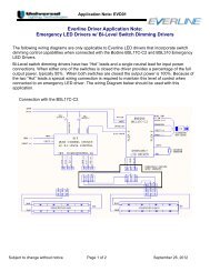
SuperDim ® <strong>Analog</strong> <strong>Dimming</strong><br />
Technical Product Information
SuperDim ® System Features<br />
<strong>Universal</strong> <strong>Lighting</strong>’s SuperDim ® analog ballasts offer the most cost-effective solution for energy-saving requirements.<br />
<strong>Universal</strong> offers a wide variety of SuperDim ballasts for T5, T8, and CFL lamps.<br />
Features:<br />
• SuperDim ® ballasts provide reliable lighting control down<br />
to 3% for all applications<br />
• Compatible with most 0–10V manufactured controls<br />
• Combine with photocells for daylight harvesting<br />
• Ideal for use with 0–10V energy management controls<br />
• Programmed rapid start technology maximizes lamp life<br />
• Low profile design for fixture design flexibility<br />
• <strong>Universal</strong> input voltage (120–277V) for installation flexibility<br />
• Starts at any level without flashing<br />
• Control input protected against miswiring<br />
• Single and multiple lamp versions are available in a variety<br />
of case configurations<br />
<strong>Dimming</strong> Controls and Accessories:<br />
SuperDim ballasts are compatible with a wide variety of<br />
popular controls and photocells. A list of these control<br />
manufacturers is available at www.unvlt.com in the energy<br />
management and controllable lighting section<br />
A list of SuperDim ® ballasts and their applications is<br />
available on the <strong>Universal</strong> website at www.unvlt.com in<br />
the energy management and controllable lighting section.<br />
1
SuperDim ® System Wiring<br />
Power Wiring<br />
• If the SuperDim ballasts use the switched line from a<br />
control device, the maximum number of units depends<br />
on the current-carrying capacity of the switch<br />
• SuperDim ballasts, and the luminaires in which they<br />
are mounted, must be properly grounded. Failure to<br />
do so will result in lamp flickering and other system<br />
malfunctions.<br />
• Each SuperDim ballast housing must make good contact<br />
with the fixture chassis for proper operation. Use of a<br />
star washer or other means of paint penetration is<br />
recommended for this.<br />
• Some ballasts are equipped with connectors. In these<br />
cases a grounding terminal is provided to facilitate the<br />
ballast-to- fixture connection.<br />
• Make the required connections and properly cap off<br />
any unused wires.<br />
Control Wiring<br />
• Do not connect the control wires to the branch circuit<br />
power conductors.<br />
• Do not ground any of the control wires. This will cause<br />
intermittent operation of SuperDim ballasts.<br />
• Polarity of control wiring must be maintained throughout<br />
the system for proper operation (purple-to-purple and<br />
gray-to-gray).<br />
Lamp Wiring<br />
• A ballast-to-lamp wiring diagram is shown on each ballast<br />
label. These diagrams must be adhered to for proper lamp<br />
and ballast operation.<br />
• Keep the lead lengths as short as practical, and do not tightly<br />
bundle the lamp wires.<br />
• Maintain consistent lead lengths and wiring practices for all<br />
fixtures in a room.<br />
• Some lamp manufacturers advise operating new lamps at full<br />
bright for at least 100 hours before dimming.<br />
• Use the same lamp type in all fixtures (within a room) to avoid<br />
uneven light levels and inconsistent colors.<br />
• Do not use instant start lamp sockets with SuperDim ballasts<br />
(see Figure 1).<br />
SuperDim ® System Installation<br />
Warning! SuperDim ballasts are to be wired according to their label diagrams<br />
and installed in accordance with national and local electrical codes.<br />
Mounting<br />
• SuperDim ballasts and modules must be mounted against a flat metal plate, which acts as a heat sink for the unit.<br />
Proper operation depends on good connection between ballast and fixture chassis. A star washer or other paint<br />
penetrating device is strongly encouraged.<br />
• Leads for any particular ballast installation must not exceed the maximum lengths identified by its Application and<br />
Performance Specification.<br />
• Fixtures equipped with SuperDim ballasts must maintain an internal ambient temperature less than or equal to 40°C, and must<br />
further maintain ballast case temperatures to within the limit expressed on its Application and Performance Specification.<br />
• Fluorescent fixtures should not be mounted in areas with cool air drafts; this may result in uneven dimming caused by low lamp<br />
temperatures.<br />
• Linear fixtures must incorporate a grounded lamp “starting aid”. The spacing between lamp wall and starting aid (grounded<br />
fixture surface) must be between 1/8th and ½ inch.<br />
• Lamps must not touch any grounded metal.<br />
• Lamp support brackets (if used) must not be metal.<br />
2
SuperDim ® <strong>Analog</strong> (0-10 volt) <strong>Dimming</strong> Ballasts<br />
Application<br />
SuperDim<br />
System Watts<br />
(Max)<br />
Input Amps<br />
(Max)<br />
Lamp No. Ballast 120V 277V 120V 277V<br />
Ballast<br />
Factor<br />
(Max)<br />
Case<br />
Style<br />
Wiring<br />
Diagram<br />
T8 - Linear Fluorescent Lamps<br />
F32T8 1 B132PUNVSV3-A 30 30 0.25 0.11 0.88 A 1<br />
F25T8 (3ft) 1 B132PUNVSV3-A 22 22 0.18 0.08 0.85 A 1<br />
F17T8 1 B132PUNVSV3-A 16 16 0.13 0.06 0.85 A 1<br />
F32T8 2 B232PUNVSV3-A 57 56 0.48 0.20 0.88 A 2<br />
F25T8 (3ft) 2 B232PUNVSV3-A 45 44 0.38 0.16 0.85 A 2<br />
F17T8 2 B232PUNVSV3-A 32 32 0.27 0.12 0.85 A 2<br />
T5 - Linear Fluorescent Lamps<br />
F35T5 1 B135PUNVSV3-D 40 39 0.33 0.14 1.00 D 3<br />
F28T5 1 B128PUNVSV3-D 32 32 0.27 0.12 1.00 D 3<br />
F21T5 1 B128PUNVSV3-D 25 25 0.21 0.10 1.01 D 3<br />
F14T5 1 B114PUNVSV3-D 17 17 0.14 0.06 1.00 D 3<br />
F28T5 2 B228PUNVSV3-D 63 61 0.53 0.22 1.00 D 4<br />
F21T5 2 B228PUNVSV3-D 47 46 0.39 0.17 1.00 D 4<br />
F14T5 2 B214PUNVSV3-D 32 32 0.27 0.12 1.00 D 4<br />
T4 - Compact Fluorescent Lamps<br />
CFTR42W/GX24q 1 C226UNVSV3ME 42 42 0.35 0.15 1.00 CDIM 5<br />
CFTR32W/GX24q 1 C226UNVSV3ME 34 34 0.28 0.12 1.00 CDIM 5<br />
CFQ26W/G24q 1 C226UNVSV3ME 28 28 0.26 0.10 1.00 CDIM 5<br />
CFTR26W/GX24q 1 C226UNVSV3ME 28 28 0.26 0.10 1.00 CDIM 5<br />
CFQ26W/G24q 2 C226UNVSV3ME 53 53 0.44 0.19 1.00 CDIM 6<br />
CFTR26W/GX24q 2 C226UNVSV3ME 53 53 0.44 0.19 1.00 CDIM 6<br />
CFQ18W/G24q 1 C218UNVSV3ME 20 20 0.17 0.08 1.00 CDIM 5<br />
CFTR18W/GX24q 1 C218UNVSV3ME 20 20 0.17 0.08 1.00 CDIM 5<br />
CFQ18W/G24q 2 C218UNVSV3ME 39 38 0.33 0.15 1.00 CDIM 6<br />
CFTR18W/GX24q 2 C218UNVSV3ME 39 38 0.33 0.15 1.00 CDIM 6<br />
CFQ13W/G24q 1 C213UNVSV3ME 16 16 0.13 0.06 1.00 CDIM 5<br />
CFTR13W/GX24q 1 C213UNVSV3ME 16 16 0.13 0.06 1.00 CDIM 5<br />
CFQ13W/G24q 2 C213UNVSV3ME 30 30 0.25 0.11 1.00 CDIM 6<br />
CFTR13W/GX24q 2 C213UNVSV3ME 30 30 0.25 0.11 1.00 CDIM 6<br />
3
Wiring Diagrams<br />
Green (ground)<br />
White (neutral)<br />
Black (line)<br />
Purple (contol +)<br />
Gray (contol -)<br />
G<br />
N<br />
L<br />
+<br />
-<br />
Ballast<br />
R<br />
R<br />
B<br />
B<br />
Red<br />
Red<br />
Blue<br />
Blue<br />
Green (ground)<br />
White (neutral)<br />
Black (line)<br />
Purple (contol +)<br />
Gray (contol -)<br />
G<br />
N<br />
L<br />
+<br />
-<br />
Ballast<br />
R<br />
R<br />
Y<br />
Y<br />
B<br />
B<br />
Red<br />
Red<br />
Yellow<br />
Yellow<br />
Blue<br />
Blue<br />
Wiring Diagram 1<br />
Wiring Diagram 2<br />
Green (ground)<br />
White (neutral)<br />
Black (line)<br />
Purple (contol +)<br />
Gray (contol -)<br />
G<br />
N<br />
L<br />
+<br />
Ballast<br />
R<br />
R<br />
B<br />
B<br />
Green (ground)<br />
White (neutral)<br />
Black (line)<br />
Purple (contol +)<br />
Gray (contol -)<br />
G<br />
N<br />
L<br />
+<br />
Ballast<br />
R<br />
R<br />
Y<br />
Y<br />
B<br />
B<br />
Wiring Diagram 3<br />
Wiring Diagram 4<br />
Gray (contol -)<br />
Purple (contol +)<br />
Black (line)<br />
White (neutral)<br />
Green (ground)<br />
+<br />
L<br />
N<br />
G<br />
Ballast<br />
B<br />
B<br />
Y<br />
Y<br />
R<br />
R<br />
Gray (contol -)<br />
Purple (contol +)<br />
Black (line)<br />
White (neutral)<br />
Green (ground)<br />
+<br />
L<br />
N<br />
G<br />
Ballast<br />
B<br />
B<br />
Y<br />
Y<br />
R<br />
R<br />
Wiring Diagram 5<br />
Wiring Diagram 6<br />
Case Styles<br />
Dimensions in inches<br />
1.71<br />
8.58<br />
16.88<br />
16.28<br />
1.18<br />
1.18<br />
.32<br />
9.50<br />
8.90<br />
1.25<br />
.26<br />
14.58<br />
1.52<br />
1.00<br />
1.06<br />
‘A’ Package<br />
‘D’ Package<br />
4.95<br />
Fixtures for use with SuperDim ballasts<br />
must be equipped with non-shunted<br />
sockets. Lamp wiring must be done<br />
according to diagrams on ballast labels<br />
.61<br />
1.19<br />
3.00<br />
4.59<br />
.24<br />
1.25<br />
1.00<br />
‘CDIM’ Package<br />
4
SuperDim System Verification<br />
Warning!! Ensure that all SuperDim devices are wired exactly as shown on<br />
the wiring diagram, and properly grounded properly before starting this step.<br />
Ballast functions should be checked before completing the installation job.<br />
Conduct the following three verification steps to make sure the system is wired correctly and working properly:<br />
• Verify ballast function, including power and lamp wiring<br />
• Verify control wire installation and dimming function<br />
• Verify control device operation<br />
Caution!! Before installing or troubleshooting any component, turn off<br />
AC power to prevent possible electric shock and equipment damage.<br />
1) Verify ballast function<br />
1. After connecting power wires to the luminaires, but before making any control wire connections, apply power to the<br />
lighting circuit. All ballasts should strike their lamps and provide full intensity. If they fail to do so, check the troubleshooting<br />
section for guidance.<br />
2. Disconnect power from the lighting circuit.<br />
2) Verify control wiring & dimming function<br />
1. Connect purple and gray control wires to all ballasts. Do not connect control wires to the lighting circuit power<br />
conductors. Do not connect the control device (wall station controller, photocell, etc.) to this circuit yet. Separately<br />
cap off all un-terminated wire ends.<br />
2. Apply power to the lighting circuit. All ballasts should strike their lamps and operate at full intensity.<br />
3. Remove power from the lighting circuit then connect the purple and gray wires together to form a short on the control<br />
circuit.<br />
4. Reapply power to the lighting circuit. All SuperDim ballasts on the control circuit should strike their lamps and operate at<br />
minimum intensity.<br />
5. If any of the ballasts behave differently, check and troubleshoot the control wiring. See the SuperDim troubleshooting<br />
section for more details if necessary.<br />
6. Disconnect power and remove the short from the control circuit.<br />
3) Verify control device options<br />
1. Connect the control device and verify its function according to its manufacturer’s instructions.<br />
5
SuperDim ® Troubleshooting Guidelines<br />
SuperDim Troubleshooting Guidelines<br />
Note: All wiring must be completed in compliance with national and local electrical codes.<br />
Note: All wiring must be completed in compliance with national and local electrical codes.<br />
Caution!! Disconnect power before servicing ballasts, fixtures or other system components.<br />
Caution!! Disconnect power before servicing ballasts, fixtures or other system components.<br />
Symptom Possible Reason Action<br />
Ballast not powered.<br />
Ballast not properly grounded.<br />
Check power wiring, luminaire disconnect, circuit breaker, etc.<br />
Fixture must be properly grounded, and ballast housing must have good electrical contact with metallic fixture<br />
chassis. Use of a star washer or other paint penetrating device is recommended for ballast mounting. Some<br />
ballasts provide a ground terminal as an alternative means to make this connection.<br />
Lamps never turn ON, or lamps flash<br />
and then turn OFF<br />
Incorrect lamps.<br />
Ensure lamp selection matches ballast capabilities.<br />
Lamp-ballast wiring error.<br />
Ensure connections between ballast and lamps are exactly as shown on ballast label.<br />
Shunted sockets. SuperDim ballasts require non-shunted Inspect or test lamp holders (sockets). With lamp removed and ballast disconnected, a shunted socket will<br />
sockets, also known as rapid-start or program-start always present a short circuit (zero ohms) between connections. Non-shunted sockets do not provide a<br />
sockets.<br />
connection (internal or external) between the blades.<br />
Poor starting aid.<br />
(not applicable to CFL models)<br />
Defective lamps.<br />
Defective ballast.<br />
Ensure that a grounded metallic surface is within proper distance of the lamps. Spacing between the lamp wall<br />
and the grounded metallic surface should be between 0.125 and 0.500 in. for the entire length of the<br />
fluorescent tube. This requirement applies to linear fluorescents only.<br />
Try lamp replacement.<br />
Try ballast replacement.<br />
Some or all fixtures stuck at minimum<br />
intensity<br />
Control wires at line potential.<br />
Controller not powered.<br />
Short circuit between control wires.<br />
Wrong polarity at one or more control circuit connection<br />
points.<br />
Carefully inspect all connections. Control circuit must not be connected to power conductors.<br />
When unpowered, some controllers may force the control voltage to a low level resulting in minimum intensity<br />
operation. Check line, neutral and ground connections.<br />
Inspect control wiring for improper connections or damage resulting in a short-circuit condition.<br />
Inspect control wiring. Sound connections, and correct polarity must be maintained throughout the control<br />
circuit: purple-to-purple and gray-to-gray.<br />
Some or all fixtures stuck at maximum<br />
intensity<br />
Ballasts do not respond to controller<br />
Control wires disconnected.<br />
Wrong controller type.<br />
Controller not powered.<br />
Control wires disconnected.<br />
Short circuit between control wires.<br />
Wrong polarity at one or more control circuit connection<br />
points.<br />
Inspect control wiring for improper connections or damage resulting in an open-circuit condition.<br />
Check control specification. Use only 0-10V control. Please see the controls compatibility chart on the<br />
SuperDim webpage for some typical examples of suitable 0-10V controls.<br />
Check line, neutral and ground connections.<br />
Inspect control wiring for improper connections or damage resulting in an open-circuit condition.<br />
Inspect control wiring for improper connections or damage resulting in a short-circuit condition.<br />
Inspect control wiring. Sound connections, and correct polarity must be maintained throughout the control<br />
circuit: purple-to-purple and gray-to-gray.<br />
Lamps flicker or strobe<br />
Lamp-ballast wiring error.<br />
Ensure connections between ballast and lamps are exactly as shown on ballast label.<br />
Shunted sockets. SuperDim ballasts require non-shunted Inspect or test lamp holders (sockets). With lamp removed and ballast disconnected, a shunted socket will<br />
sockets, also known as rapid-start or program-start always present a short circuit (zero ohms) between connections. Non-shunted sockets do not provide a<br />
sockets.<br />
connection (internal or external) between the blades.<br />
Poor starting aid.<br />
(not applicable to CFL models)<br />
Incorrect lamps.<br />
Excessive lead lengths.<br />
Ballast not properly grounded.<br />
Ensure that a grounded metallic surface is within proper distance of the lamps. Spacing between the lamp wall<br />
and the grounded metallic surface should be between 0.125 and 0.500 in. for the entire length of the<br />
fluorescent tube. This requirement applies to linear fluorescents only.<br />
Ensure lamp selection matches ballast capabilities.<br />
Lamp leads must not exceed their specified lengths and, when practical, excess length should be removed.<br />
Lamp leads should not be bunched, bundled or tightly dressed by wire ties or other means.<br />
Fixture must be properly grounded, and ballast housing must have good electrical contact with metallic fixture<br />
chassis. Use of a star washer or other paint penetrating device is recommended for ballast mounting. Some<br />
ballasts provide a ground terminal as an alternative means to make this connection.<br />
Cold lamps<br />
New lamps<br />
Ensure ambient temperature meets or exceeds the ballast's minimum starting temperature and is also suitable<br />
for the selected lamps.<br />
Some lamp manufacturers recommend burning lamps at full intensity for at least 12 hours before dimming.<br />
Loose connection.<br />
Ballast not properly grounded.<br />
Check power wiring, luminaire disconnect, circuit breaker, etc.<br />
Check control circuit for intermittent connections.<br />
Fixture must be properly grounded, and ballast housing must have good electrical contact with metallic fixture<br />
chassis. Use of a star washer or other paint penetrating device is recommended for ballast mounting. Some<br />
ballasts provide a ground terminal as an alternative means to make this connection.<br />
Intermittent or unpredictable operation Shunted sockets. SuperDim ballasts require non-shunted Inspect or test lamp holders (sockets). With lamp removed and ballast disconnected, a shunted socket will<br />
sockets, also known as rapid-start or program-start always present a short circuit (zero ohms) between connections. Non-shunted sockets do not provide a<br />
sockets.<br />
connection (internal or external) between the blades.<br />
Lamps ends turn black and/or frequent<br />
lamp failures<br />
Poor starting aid.<br />
(not applicable to CFL models)<br />
Shunted sockets. SuperDim ballasts require non-shunted<br />
sockets, also known as rapid-start or program-start<br />
sockets.<br />
Lamp-ballast wiring error.<br />
Incorrect lamps.<br />
Ensure that a grounded metallic surface is within proper distance of the lamps. Spacing between the lamp wall<br />
and the grounded metallic surface should be between 0.125 and 0.500 in. for the entire length of the<br />
fluorescent tube. This requirement applies to linear fluorescents only.<br />
Inspect or test lamp holders (sockets). With lamp removed and ballast disconnected, a shunted socket will<br />
always present a short circuit (zero ohms) between connections. Non-shunted sockets do not provide a<br />
connection (internal or external) between the blades.<br />
Ensure connections between ballast and lamps are exactly as shown on ballast label.<br />
Ensure lamp selection matches ballast capabilities.<br />
Additional Troubleshooting Techniques<br />
In some cases, the troubleshooting methods outlined above may not lead to a quick detection and resolution of the problem. In this case, it is often beneficial to perform one or more of the following methods.<br />
Method<br />
System division<br />
Bypass installed control wires and do<br />
step-wise system reconstruction<br />
Explanation<br />
When a large system of SuperDim ballasts has an apparent malfunction, but the specific component or location of the malfunctions is unknown, the system can be divided<br />
near the center of the control circuit. If the malfunction persists on one side, but not the other, the scope of the troubleshooting effort is reduced. Further separations may<br />
be used, of course, to help find the actual trouble site.<br />
When the cause of a malfunction cannot be assigned to a ballast or to the control wires, ballasts can be individually tested using a known good controller connected by<br />
external control wires. The system can then be reconstructed in steps, using only a few ballasts and short sections of the installed control wiring at one time. If a problem<br />
is encountered during this process, the cause can often be attributed to the ballast or control wires added in the last step.<br />
6
IT’S EASY TO REACH US...<br />
<strong>Universal</strong> <strong>Lighting</strong> <strong>Technologies</strong>, Inc.<br />
26 Century Blvd., Suite 500<br />
Nashville, TN 37214-3683<br />
General Info: (615) 316-5100<br />
For Technical Engineering Services (TES),<br />
application support and warranty information,<br />
call 1-800-BALLAST<br />
All specification information is subject to change without notification.<br />
Lit# SDTB0211<br />
Website: www.unvlt.com<br />
Email: webmaster@unvlt.com<br />
<strong>Universal</strong> <strong>Lighting</strong> <strong>Technologies</strong> is a subsidiary of Panasonic<br />
Electric Works Co., Ltd., a member of the Panasonic Group