Technical Product Information - Universal Lighting Technologies
Technical Product Information - Universal Lighting Technologies
Technical Product Information - Universal Lighting Technologies

You also want an ePaper? Increase the reach of your titles
YUMPU automatically turns print PDFs into web optimized ePapers that Google loves.
<strong>Universal</strong> <strong>Lighting</strong> <strong>Technologies</strong> is a subsidiary of Panasonic<br />
Electric Works Co., Ltd., a member of the Panasonic Group<br />
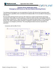
<strong>Technical</strong> <strong>Product</strong> <strong>Information</strong>
DCL ® with DEMANDflex ®<br />
DEMANDflex ® ballasts are high efficiency program start ballasts with the flexibility to be tuned at the circuit level to fixed power<br />
levels during installation. They are fully compatible with occupancy sensors and exceed the CEE requirements for high efficiency<br />
program start T8 ballasts. DEMANDflex ® ballasts have tuning capabilities with ranges from 100% to 50% power levels, making<br />
them applicable for a wide range of lighting installations.<br />
DEMANDflex ® ballasts can be tuned to maximize energy savings with fixed light levels. No dimming control wires are associated<br />
with DEMANDflex ® ballasts making them easy to install in all existing fluorescent lighting applications. And DEMANDflex ® ballasts<br />
can be integrated with DCL ® controls to create the most cost-effective lighting system available.<br />
DCL ® controls provide local control with energy management systems and external control via the internet for networked managed<br />
systems. DCL ® controls allow integration with utility demand response programs providing incentives to end-users in exchange for<br />
reduction of lighting power levels during periods of peak demand.<br />
DEMANDflex ® Ballasts<br />
• Power level tuning potential to 50%<br />
- Set the circuit power level at installation<br />
- Typical 10% to 15% power reduction<br />
• Install the same as standard PRS ballasts<br />
- No control wires necessary<br />
- Standard mounting footprint<br />
- Same wiring as program rapid start ballasts<br />
• High efficiency program start operation<br />
- Exceeds CEE T8 requirements<br />
- Compatible with occupancy sensors<br />
DCL ® Controlled Systems<br />
• Reduces lighting power by up to 50%<br />
- Avoid high peak charges<br />
- Reduce demand costs<br />
• Programmable fade rates<br />
- Gradual transitions - No disruptions<br />
• Use existing power connections to<br />
communicate to the ballasts<br />
- No control wires<br />
• Implement with various controls and systems<br />
- BAS Systems<br />
- Photo Cells<br />
- Occupancy sensors<br />
- Contact Closure<br />
DCL ® provides flexibility<br />
for a wide variety<br />
of control applications.<br />
1
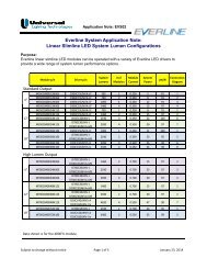
DCL ® System Features and Components<br />
DEMANDflex ® Ballast & DCL ® Control Configuration<br />
DCL ® Control systems use the existing power line<br />
to communicate commands to the DEMANDflex ®<br />
ballasts. Each 20-Amp lighting circuit has its<br />
own controller and the controllers are combined<br />
together in control panels which hold up to 12<br />
circuit controllers. Individual circuit controllers<br />
are also available as stand alone devices (Single<br />
Circuit Controls) when panels are not practical.<br />
Circuit Controller Connection<br />
within the <strong>Lighting</strong> Circuit<br />
The DCL ® control panels and single control<br />
modules are connected between the lighting<br />
panel and fluorescent ballasts. The control<br />
modules communicate with the ballasts on the<br />
circuit. Since each circuit has its own controller,<br />
the circuits can be controlled at different power<br />
levels. This increases the flexibility of the lighting<br />
management system, maximizing savings in one<br />
ocation without affecting the lighting in other parts<br />
of the facility.<br />
DCL ® Circuit controllers receive commands from a<br />
lighting control unit. Depending on the configuration,<br />
the lighting control unit may be integrated with local<br />
controls such as occupancy sensors, photo cells,<br />
and manual controls, or it may be connected to a<br />
building’s energy management system. Multiple<br />
configurations can be developed to meet the<br />
specific requirements of the facility.<br />
The Circuit Controller is connected between<br />
the lighting circuit breaker panel and the lighting<br />
fixtures. The Circuit Controller may be incorporated<br />
in a DCL ® panel or installed seperately as a standalone<br />
device. Tuning applications will temporarily<br />
connect a controller to program the ballasts.<br />
Circuit Tuning<br />
(For installations without DCL ® Controls)<br />
Some projects may initially install DEMANDflex ® ballasts and tune their lighting circuits preserving an option to install controls<br />
at a later date. The tuning process uses a commissioning kit which includes a single circuit controller, interface device and<br />
cable. Circuits are programmed one at a time to selected power levels. The tuned levels should be documented during this<br />
process.<br />
2
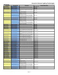
DEMANDflex ® Ballasts<br />
“Max. Power<br />
(Watts)”<br />
“Max. Current<br />
(Amps)”<br />
Ballast<br />
Factor<br />
(Max)<br />
Min. Power<br />
(Watts)<br />
T8 120 277 120 277 120 277<br />
Ballast<br />
Factor<br />
(Min.)<br />
(2) F32T8 B232PUNVDRL-A 47 47 .40 .17 0.71 24 24 0.19 A 2a<br />
(2) F32T8 B232PUNVDR-A 57 56 .47 .20 0.87 28 28 0.35 A 2a<br />
(2) F32T8 B232PUNVDRH-A 75 73 .62 .26 1.15 37 36 0.50 A 2a<br />
(3) F32T8 B332PUNVDRL-A 72 72 .59 .25 0.71 36 36 0.22 A 3a<br />
(3) F32T8 B332PUNVDR-A 85 83 .70 .30 0.87 42 41 0.35 A 3a<br />
(3) F32T8 B332PUNVDRH-E 115 111 .95 .41 1.15 57 55 0.50 E 3b<br />
(3) F32T8 B432PUNVDRL-E 93 93 .78 .34 0.71 47 47 0.21 E 4a<br />
(4) F32T8 B432PUNVDR-E 116 112 .96 .41 0.88 58 56 0.35 E 4a<br />
Case<br />
Style<br />
Wiring<br />
Dia.<br />
T5HO<br />
(2) F54T5HO B254PUNVDR-D 120 120 1.00 .43 1.00 60 60 0.45 D 2b<br />
T5<br />
(2) F28T5 B228PUNVDRH-D 74 72 .62 .26 1.15 36 36 .48 D 2b<br />
(1) F28T5 B128PUNVDRH-D 37 37 .32 .14 1.15 19 19 .38 D 2c<br />
Dimensions (inches)<br />
Case Style Length Width Height Mount Length<br />
A 9.50 1.70 1.18 8.89<br />
D 16.88 1.18 1.00 16.20<br />
E 16.88 1.82 1.18 16.28<br />
Nominal dimensions: Contact <strong>Universal</strong> for drawings.<br />
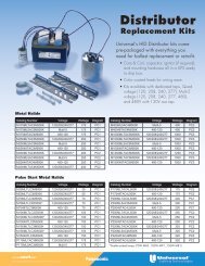
DCL ® Controls<br />
Model<br />
LP12DCLUNV-xx**<br />
SC20DCLUNV**<br />
MC20DCLUNV**<br />
RSMDCL51<br />
WTPDCL51 ∆<br />
WPS5527K<br />
Description<br />
Circuit Control Panel<br />
Single Circuit Controller<br />
Open Style Single Circuit Controller<br />
Contact Interface Controller<br />
Time/Photo Controller<br />
Photo Sensor for WTPDCL<br />
LP12DCLUNV-xx<br />
Dimensions<br />
Mounting<br />
Length 32” 24”<br />
Width 20” 16”<br />
Depth 4.3” ––<br />
The quantity of individual controllers installed<br />
is determined by the model number.<br />
xx = number of circuits (03 - 12)<br />
* For additional lighting system controllers, contact <strong>Universal</strong> <strong>Lighting</strong>.<br />
** Modbus versions of these controls are available.<br />
∆<br />
Consult <strong>Universal</strong> for configuration options.<br />
LP12DCLUNV-xx<br />
Circuit Control Panel<br />
SC20DCLUNV<br />
Mounting Pattern<br />
SC20DCLUNV<br />
Single Circuit Controller<br />
MC20DCLUNV<br />
Open Style,<br />
Single Circuit Controller<br />
Dimensions<br />
Length 9.66”<br />
Width 3.98”<br />
Depth 3.21”<br />
8.46<br />
X<br />
X<br />
1.50 2.50<br />
X<br />
X<br />
3
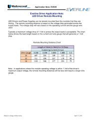
Wiring Diagrams<br />
Diagram 2a<br />
Diagram 2b<br />
Line<br />
Neutral<br />
Black<br />
White<br />
B<br />
A<br />
L<br />
L<br />
A<br />
S<br />
T<br />
Red<br />
Red<br />
Blue<br />
Blue<br />
Diagram 2c<br />
Diagram 3a<br />
Diagram 3b<br />
Diagram 4a<br />
4
DEMANDflex ® Ballasts<br />
Installation Guidelines:<br />
Lamp Sockets<br />
Rapid Start type lamps sockets must be used with all<br />
DEMANDflex ® ballasts. Instant start sockets which are<br />
shunted internally or externally will damage ballasts<br />
and lamps.<br />
Remote Mounting Lead Lengths<br />
DEMANDflex ® ballasts should be mounted within the same<br />
fixture in which the lamps are operated. The maximum<br />
allowable lead length from the ballast to the lamp sockets<br />
is 8 feet.<br />
Tandem Wiring<br />
DEMANDflex ® ballasts should not be tandem wired. Consult<br />
factory for more information on special conditions<br />
Wiring Configuration<br />
Ballasts must be wired according to the wiring diagram on<br />
the ballast label. Special attention should be paid to the<br />
wiring of the common filaments. With some models, these<br />
are wired in parallel but other models have them connected<br />
in series.<br />
Grounding<br />
As with other ballasts, DEMANDflex ® ballasts must be<br />
grounded. This is accomplished by mounting the ballast to<br />
a grounded metal fixture. When grounding ballasts, remove<br />
the paint from the ground point of the ballast or use a star<br />
washer with the ballast mounting screw. Poor grounding will<br />
create problems with the starting of the lamps. Grounding is<br />
also necessary to suppress EMI/RFI that is generated within<br />
the ballast.<br />
Initial Operation<br />
Burn lamps at full brightness for at least 12 hours before<br />
dimming for the first time.<br />
Fixture Wiring<br />
The lead lengths in the fixture should be kept as short as possible.<br />
In multi-lamp fixtures, the red and blue leads should be<br />
kept separate and not be bundled or twisted together.<br />
Installations resulting in twisted, folded, or bundled lamp<br />
wires, and applications routing lamp wires in very narrow<br />
channels, should be validated by test. This test should be<br />
conducted at the target input voltage, and at both the maximum<br />
and minimum intensity levels. Test criteria should include<br />
acceptable starting performance with cold lamps as well as<br />
steady and uniform illumination during and after stabilization<br />
of the lamp temperature.<br />
Starting Aid Distance<br />
Linear lamp fixtures must incorporate a grounded lamp ‘Starting<br />
aid’ (Grounded Fixture Surface). Linear lamp to starting<br />
aid spacing must be 1⁄8 to 3 ⁄4 inch. Lamps must not touch<br />
any grounded metal. (Lamp support brackets (if any) must not<br />
be metal.)<br />
Tuning<br />
The DEMANDflex ® commissioning kit (tuning tool) is used to program/tune DEMANDflex ® ballasts when DCL ® controls are<br />
not installed and a lower power level is desirable. When programming the desired power level, this circuit programming tool<br />
is temporarily connected in series between the lighting circuit panel and the lighting circuit.<br />
When the tuning tool is connected, simple control buttons are used to adjust the power level with the use of LCD display.<br />
When the desired levels are selected, the program command is sent with the press of a button. When the tuning tool is disconnected<br />
and the circuit is re-connected, the ballast will operate at its programmed level.<br />
Ballasts intended to be programmed must be powered ‘on’ and have lamps installed during programming. If DEMANDflex ®<br />
ballasts on the same circuit need to be tuned to different levels, ballasts can be disconnected at the fixture or by wall switches<br />
to accomplish this. DEMANDflex ® ballasts can be re-programmed, always maintaining their latest programmed command as<br />
their operating level.<br />
5
DCL ® Controls<br />
Installation Guidelines:<br />
LP12DCLUNV-xx Control Panel<br />
The two digit number at the end of the LP12DCLUNV-xx indicates the number of circuit control modules which are incorporated<br />
within the LP12 control panel. Each module is designed for a 20 amp circuit for any voltage ranging from 120 to 277 volts.<br />
Proper circuit de-rating to 15.5 amps is required by electrical codes.<br />
The LP12DCLUNV-xx circuit control panel should be mounted adjacent to the lighting circuit panel to simplify installation. Wires<br />
that run to the lighting fixtures should be connected to the circuit control panel and new wires should be used to connect the circuit<br />
control panel to the lighting circuit panel.<br />
A network cable (CAT 5e) connects the<br />
control panel to the system controller.<br />
SC20DCLUNV Single Circuit Control<br />
For applications with few circuits or limited wall<br />
space, the SC20DCLUNV single circuit control<br />
can be used. This control has one control module<br />
and can be mounted in a much smaller space or<br />
even in the ceiling plenum. The SC20DCLUNV has<br />
wiring compartments which allow for the power<br />
connections to be made in compliance with<br />
electrical codes.<br />
The SC20DCLUNV is designed for a 20 amp<br />
circuit for any voltage ranging from 120 to 277<br />
volts. Proper circuit de-rating to 15.5 amps is<br />
required by electrical codes.<br />
A Standard CAT-5E cable is used to connect the<br />
SC20DCLUNV to the system controller or other<br />
circuit control modules. Two RS-485 plugs on each<br />
circuit controller permit multiple circuit controls to be<br />
daisy chained.<br />
<strong>Lighting</strong> System Controls<br />
<strong>Lighting</strong> System Controls (e.g., RSMDCL51 or WTPDCL51) should be mounted adjacent to the control panel. A<br />
network cable connects the control modules to the system control. When using single circuit controllers, a longer cable may be<br />
made using CAT-5E cable and RJ45 connectors. The specified control configuration will determine<br />
the connections to the system control module from other network or building controls.<br />
Temperature<br />
The maximum allowable ambient temperature for DCL® controls is 40°C.<br />
6
IT’S EASY TO REACH US...<br />
<strong>Universal</strong> <strong>Lighting</strong> <strong>Technologies</strong>, Inc.<br />
26 Century Blvd., Suite 500<br />
Nashville, TN 37214-3683<br />
General Info: (615) 316-5100<br />
For <strong>Technical</strong> Engineering Services (TES),<br />
application support and warranty information,<br />
call 1-800-BALLAST<br />
All specification information is subject to change without notification.<br />
Lit# DCLTECH0611<br />
Website: www.unvlt.com<br />
Email: webmaster@unvlt.com<br />
<strong>Universal</strong> <strong>Lighting</strong> <strong>Technologies</strong> is a subsidiary of Panasonic<br />
Electric Works Co., Ltd., a member of the Panasonic Group